Page is loading ...

For more information on POPIT installation (including wire type, length, and run) and
programming, refer to the D8125 POPEX Operation and Installation Guide (P/N: 74-04247-000)
and control panel operation, installation, and programming manuals.
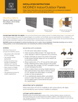
Install a 33 kΩ end-of-line
resistor at the farthest point on the loop for proper supervision. Replace the POPIT cover
when the wiring is completed.
Callout ― Description
1 ― D8125 POPEX Module
2 ― D9127U/T POPIT Module
3 ― Tab
4 ― DIP Switch
5 ― Reed switch (D9127T only)
6 ― Detector loop
7 ― 33 kΩ EOL resistor
8 ― Terminals (all): 12 AWG solid (maximum); 22 AWG (0.1 mm) stranded (minimum)
9 ― Zone expansion loop to other POPITs
10 ― Supervised
11 ― Wire opening of POPIT base
Figure 1: POPIT Wiring
-
-
+
+
GND
OUT
IN
AUX
DATA
LOOP
- - + + - +
(-)
(+)
1
4
3
2
5
6
7
8
9
11
3
10
3
NOTICE!
When using 12 AWG (0.1 mm) maximum wire, use solid wire. If you use stranded
wire, take care to insert all of the strands into the terminal block.
3 | Wiring Instructions
2 | Installation
2.1 | Remove the cover
2.2 | Remove the PCB
2.3 | Mount the POPIT base
Pull the wiring through the wiring opening
(refer to Figure 1). Mount the POPIT base
using the supplied hardware to prevent
shorting the PCB.
2.4 | Replace the PCB
1. Grasp the terminal block on the PCB with
one hand. Insert the DIP switch end of the
PCB under the single tab.
2. Carefully but firmly, pull the two tabs on
the opposite ends away from the PCB.
3. Gently lay the PCB in place and, if
necessary, carefully, push the two tabs
toward the PCB until the PCB is firmly in
place.
1. Insert a small flat-head screwdriver into
one of the small slots in the side of the
POPIT.
2. Twist the screwdriver and remove the
cover.
1. Grasp the terminal block on the PCB in
one hand.
2. Three tabs hold the PCB. At the end with
the two tabs, carefully but firmly, push
one tab away from the PCB and lift the
corner.
3. Carefully but firmly, push the other tab
away from the PCB and lift the entire
PCB from the base.
Control
panel
DIP switch 0 setting
D7212B1
D8112
D9112B1
Leave switch 0 ON.
D9412 Refer to 9000 Series
Operation
and Installation Guide
(P/N: 74-07692-000).
D9412G
D7412G
Refer to Section 4.
D7212G Refer to Section 4.
D7212GV2 Refer to Section 4.
D7212GV3 Refer to Section 4.
D7212GV4
D9412GV4
D7412GV4
Refer to Section 4.
B9512G
B9512G-E
B8512G
B8512G-E
Refer to Section 4.
For additional D9127 installation
information, refer to the compatible panel
installation documentation.
Table 1: DIP switch 0 setting
Use the steps in this section to install and
configure the POPIT module.
2.5 | Configuration of DIP switch
Refer to Table 1 for DIP switch 0 settings and
Section 4 for DIP switch configuration settings
for ZONEX and ZONEX 2.
1 | Overview
The D9127 Series POPIT Modules includes
the D9127T (with magnetic tamper switch)
and the D9127U (without tamper). They
are used with a compatible control panel
to expand beyond its standard number of
on-board initiating points. Future system
expansion is very economical as D9127
Series POPITs can be added anywhere
along the two-wire data expansion loop.
Both modules include proven technology
that combines point supervision with
individual device addressing on one pair
of wires. Screw terminals provide reliable
connections for the data expansion loop
and supervised sensor loop wiring.
The units are small and easily installed in
standard outlet boxes, above false ceilings,
closets, or other accessible locations.

© 2016 Bosch Security Systems, Inc.
4998132020 | 11 | 2016.01
en Installation Guide
Bosch Security Systems, Inc.
130 Perinton Parkway
Fairport, NY 14450
USA
www.boschsecurity.us
POPIT Module
D9127U/T
Copyright
This document is the intellectual property of
Bosch Security Systems, Inc. and is protected
by copyright. All rights reserved.
Trademarks
All hardware and software product names used
in this document are likely to be registered
trademarks and must be treated accordingly.
Bosch Security Systems, Inc. product
manufacturing dates
Use the serial number located on the product
label and refer to the Bosch Security Systems,
Inc. website at
http://www.boschsecurity.com/datecodes/.
5 | Specifications
Operating Voltage Nominal 12 VDC
supplied by control
panel
Operating Current
per D9127U/T
0.8 mA Standby
0.8 mA Alarm
4 | ZONEX and ZONEX 2 point address chart
Address
1
Switch
ZONEX
1
ZONEX
2
B299
0 1 2 3 4 5 6
009 129 x00*
ON ON ON ON ON ON ON
010 130 x01*
ON ON ON ON ON ON
011 131 x02*
ON ON ON ON ON ON
012 132 x03*
ON ON ON ON ON
013 133 x04*
ON ON ON ON ON ON
014 134 x05*
ON ON ON ON ON
015 135 x06*
ON ON ON ON ON
016 136 x07*
ON ON ON ON
017 137 x08*
ON ON ON ON ON ON
018 138 x09
ON ON ON ON ON
019 139 x10
ON ON ON ON ON
020 140 x11
ON ON ON ON
021 141 x12
ON ON ON ON ON
022 142 x13
ON ON ON ON
023 143 x14
ON ON ON ON
024 144 x15
ON ON ON
025 145 x16
ON ON ON ON ON ON
026 146 x17
ON ON ON ON ON
027 147 x18
ON ON ON ON ON
028 148 x19
ON ON ON ON
029 149 x20
ON ON ON ON ON
030 150 x21
ON ON ON ON
031 151 x22
ON ON ON ON
032 152 x23
ON ON ON
033 153 x24
ON ON ON ON ON
034 154 x25
ON ON ON ON
035 155 x26
ON ON ON ON
036 156 x27
ON ON ON
037 157 x28
ON ON ON ON
038 158 x29
ON ON ON
039 159 x30
ON ON ON
040 160
x31
ON ON
041 161
x32
ON ON ON ON ON ON
042 162
x33
ON ON ON ON ON
043 163
x34
ON ON ON ON ON
044 164
x35
ON ON ON ON
045 165
x36
ON ON ON ON ON
046 166
x37
ON ON ON ON
047 167
x38
ON ON ON ON
048 168
x39
ON ON ON
049 169
x40
ON ON ON ON ON
050 170
x41
ON ON ON ON
051 171
x42
ON ON ON ON
052 172
x43
ON ON ON
053 173
x44
ON ON ON ON
054 174
x45
ON ON ON
055 175
x46
ON ON ON
056 176
x47
ON ON
057 177
x48
ON ON ON ON ON
058 178
x49
ON ON ON ON
059 179 x50
ON ON ON ON
1
ZONEX 1: Points 9 to 127 (D9412G); Points 9 to 75 (D7412G).
ZONEX 2: Points 129 to 247 (D9412G).
B299: x = B299 module address 0-5
* These point numbers are not available for B299 address 0.
Address
1
Switch
ZONEX
1
ZONEX
2
B299
0 1 2 3 4 5 6
060 180 x51
ON ON ON
061 181 x52
ON ON ON ON
062 182 x53
ON ON ON
063 183 x54
ON ON ON
064 184 x55
ON ON
065 185 x56
ON ON ON ON
066 186 x57
ON ON ON
067 187 x58
ON ON ON
068 188 x59
ON ON
069 189 x60
ON ON ON
070 190 x61
ON ON
071 191 x62
ON ON
072 192 x63
ON
073 193 x64
ON ON ON ON ON ON
074 194 x65
ON ON ON ON ON
075 195 x66
ON ON ON ON ON
076 196 x67
ON ON ON ON
077 197 x68
ON ON ON ON ON
078 198 x69
ON ON ON ON
079 199 x70
ON ON ON ON
080 200 x71
ON ON ON
081 201 x72
ON ON ON ON ON
082 202 x73
ON ON ON ON
083 203 x74
ON ON ON ON
084 204 x75
ON ON ON
085 205 x76
ON ON ON ON
086 206 x77
ON ON ON
087 207 x78
ON ON ON
088 208 x79
ON ON
089 209 x80
ON ON ON ON ON
090 210
x81
ON ON ON ON
091 211
x82
ON ON ON ON
092 212
x83
ON ON ON
093 213
x84
ON ON ON ON
094 214
x85
ON ON ON
095 215
x86
ON ON ON
096 216
x87
ON ON
097 217
x88
ON ON ON ON
098 218
x89
ON ON ON
099 219
x90
ON ON ON
100 220
x91
ON ON
101 221
x92
ON ON ON
102 222
x93
ON ON
103 223
x94
ON ON
104 224
x95
ON
105 225
x96
ON ON ON ON ON
106 226
x97
ON ON ON ON
107 227
x98
ON ON ON ON
108 228
x99
ON ON ON
109 229
ON ON ON ON
110 230
ON ON ON
1
ZONEX 1: Points 9 to 127 (D9412G); Points 9 to 75 (D7412G).
ZONEX 2: Points 129 to 247 (D9412G).
B299: x = B299 module address 0-5
* These point numbers are not available for B299 address 0.
Address
1
Switch
ZONEX
1
ZONEX
2
B299
0 1 2 3 4 5 6
111 231
ON ON ON
112 232
ON ON
113 233
ON ON ON ON
114 234
ON ON ON
115 235
ON ON ON
116 236
ON ON
117 237
ON ON ON
118 238
ON ON
119 239
ON ON
120 240
ON
121 241
ON ON ON ON
122 242
ON ON ON
123 243
ON ON ON
124 244
ON ON
125 245
ON ON ON
126 246
ON ON
127 247
ON ON
128 248
not available
1
ZONEX 1: Points 9 to 127 (D9412G); Points 9 to 75 (D7412G).
ZONEX 2: Points 129 to 247 (D9412G).
B299: x = B299 module address 0-5
* These point numbers are not available for B299 address 0.
Bosch Sicherheitssysteme
GmbH
Robert-Bosch-Ring 5
85630 Grasbrunn
Germany
/