Page is loading ...

NXG-EAS
User Manual
Stock # Model Name Description
6778 NXG-EAS NXG Emergency Alert System for IP (1 Zone)
All Rights Reserved. Specifications subject to change without notice. All trademarks are property of their respective owners.
© Blonder Tongue Labs, Inc.
ISO 9001:2015 Certified
P/N: 651250400A
|
Rev: 032020
Emergency Alert System Module

2 NXG-EAS Module
User Manual
Returning Product for Repair (or Credit)
Before returning product, please contact the Blonder Tongue Service
Department at 1-800-523-6049, Ext. 4256 or visit our website: for further informaon.
This guide makes use of hyperlinks for the Table of Contents, some cross-reference linking between secons, and
external hyperlinking to web addresses. This has been done to assist the reader in nding the informaon they are
seeking in a much quicker way. In addion to hyperlinking, the Table of Contents also makes use of the bookmarking
feature present in the Adobe Reader applicaon.
Download the latest User Manual (PDF) by vising our website. Navigate to the product page by entering the full Model
Name or Stock Number in the search eld. Upon reaching the product page, the “User Manual” download link will be
located beneath the product image. are available under “Tech Support” in the “Resources” secon
of the website. General instrucons for the FTP site, as well as updang your rmware, are provided on this page.
We recommend that you write the following informaon in the spaces provided below.
The informaon contained herein is subject to change without noce. Revisions may be issued to advise
of such changes and/or addions.
Correspondence regarding this publicaon should be addressed directly to:
Blonder Tongue Laboratories, Inc.
One Jake Brown Road
Old Bridge, NJ 08857 USA
Document Number: 651250400A
Printed in the United States of America.
All product names, trade names, or corporate names menoned in this document are acknowledged to
be the proprietary property of the registered owners.
This product incorporates copyright protecon technology that is protected by U.S. patents and other
intellectual property rights. Reverse engineering or disassembly is prohibited.
Purchase Locaon Name:
Purchase Locaon Telephone Number:
NXG-EAS Module Serial Number:

3NXG-EAS Module
User Manual
4
5
2.1 REVISION HISTORY & REASON .............................................................................................................................. 5
2.2 PRODUCT APPLICATION & FEATURES ................................................................................................................... 5
2.3 MODULE SPECIFICATION ....................................................................................................................................... 6
2.4 MODULE INSTALLATION ......................................................................................................................................... 6
7
3.1 MODULE STATUS ..................................................................................................................................................... 7
3.2 DETECTED ISSUES ................................................................................................................................................... 7
3.3 MODULE INFORMATION ........................................................................................................................................ 8
8
4.1 CONFIGURATION SETTINGS AND PARAMETERS ................................................................................................. 8
5.1 EAS TRIGGER CONFIGURATION ............................................................................................................................ 10
5.2 TESTING THE EAS SETTINGS ................................................................................................................................. 11
5.3 MODULE ETHERNET CONFIGURATION ................................................................................................................ 11
6.1 MODULE SETTINGS CONFIGURATION ................................................................................................................. 12
6.2 MODULE REBOOT .................................................................................................................................................. 12
STEP 1: SETTING UP AN EMERGENCY ALERT SYSTEM WITH THE NEXGEN EAS MODULE .................................... 15
STEP 2: CONFIGURING THE EAS .................................................................................................................................. 16

4 NXG-EAS Module
User Manual
å Elevated Operating Ambient - If installed in a closed or multi-unit rack assembly,
the operating ambient temperature of the rack environment may be greater
than room ambient. Therefore, consideration should be given to installing
the equipment in an environment compatible with the maximum ambient
temperature per Section 2.3.
å Reduced Air Flow - Installation of the equipment in a rack should be such that
the amount of air flow required for safe operation of the equipment is not
compromised.
å Mechanical Loading - Mounting of the equipment in the rack should be such
that a hazardous condition is not achieved due to uneven mechanical loading.
å Circuit Overloading - Consideration should be given to the connection of
the equipment to the supply circuit and the effect that overloading of the
circuits might have on overcurrent protection and supply wiring. Appropriate
consideration of equipment nameplate ratings should be used when addressing
this concern.
å Reliable Earthing - Reliable earthing of rack-mounted equipment should be
maintained. Particular attention should be given to supply connections other
than direct connections to the branch circuit (e.g. use of power strips).
å Read all safety and operating instructions before you operate the unit.
å Retain all safety and operating instructions for future reference.
å Heed all warnings on the unit and in the safety and operating instructions.
å Follow all installation, operating, and use instructions.
å Unplug the unit from the AC power outlet before cleaning. Use only a damp
cloth for cleaning the exterior of the unit.
å Do not use accessories or attachments not recommended by Blonder Tongue,
as they may cause hazards, and will void the warranty.
å Do not operate the unit in high-humidity areas, or expose it to water or
moisture.
å Do not place the unit on an unstable cart, stand, tripod, bracket, or table. The
unit may fall, causing serious personal injury and damage to the unit. Install the
unit only in a mounting rack designed for 19” rack-mounted equipment.
å Do not block or cover slots and openings in the unit. These are provided for
ventilation and protection from overheating. Never place the unit near or over
a radiator or heat register. Do not place the unit in an enclosure such as a cabinet
without proper ventilation. Do not mount equipment in the rack space directly
above or below the unit.
å Operate the unit using only the type of power source indicated on the marking
label. Unplug the unit power cord by gripping the plug, not the cord.
å The unit is equipped with a three-wire ground-type plug. This plug will fit only
into a ground-type power outlet. If you are unable to insert the plug into the
outlet, contact an electrician to replace the outlet. Do not defeat the safety
purpose of the ground-type plug.
å Route power supply cords so that they are not likely to be walked on or pinched
by items placed upon or against them. Pay particular attention to cords at plugs,
convenience receptacles, and the point where they exit from the unit.
The STOP sign symbol is intended to alert you to the
presence of REQUIRED operating and maintenance
(servicing) instructions that if not followed, may result in
product failure or destruction.
The YIELD sign symbol is intended to alert you to the
presence of RECOMMENDED operating and maintenance
(servicing) instructions.
The LIGHTNING flash symbol is intended to alert you
to the presence of uninsulated “dangerous voltage”
within the product's enclosure that may be of sufficient
magnitude to constitute a risk of electrical shock.
å Be sure that the outdoor components of the antenna system are grounded in
accordance with local, federal, and National Electrical Code (NEC) requirements.
Pay special attention to NEC Sections 810 and 820. See the example shown in
the following diagram:
å We strongly recommend using an outlet that contains surge suppression or
ground fault protection. For added protection during a lightning storm, or when
the unit is left unattended and unused for long periods of time, unplug it from
the wall outlet and disconnect the lines between the unit and the antenna. This
will prevent damage caused by lightning or power line surges.
å Do not locate the antenna near overhead power lines or other electric light
or power circuits, or where it can fall into such power lines or circuits. When
installing the antenna, take extreme care to avoid touching such power lines or
circuits, as contact with them can be fatal.
å Do not overload wall outlets or extension cords, as this can result in a risk of fire
or electrical shock.
å Never insert objects of any kind into the unit through openings, as the objects
may touch dangerous voltage points or short out parts. This could cause fire or
electrical shock.
å Do not attempt to service the unit yourself, as opening or removing covers may
expose you to dangerous voltage and will void the warranty. Refer all servicing
to authorized service personnel.
å Unplug the unit from the wall outlet and refer servicing to authorized service
personnel whenever the following occurs:
o The power supply cord or plug is damaged;
o Liquid has been spilled, or objects have fallen into the unit;
o The unit has been exposed to rain or water;
o The unit has been dropped or the chassis has been damaged;
o The unit exhibits a distinct change in performance.
å When replacement parts are required, ensure that the service technician uses
replacement parts specified by Blonder Tongue. Unauthorized substitutions
may damage the unit or cause electrical shock or fire, and will void the warranty.
å Upon completion of any service or repair to the unit, ask the service technician
to perform safety checks to ensure that the unit is in proper operating condition.

5NXG-EAS Module
User Manual
This is the rst release of this manual.
• SCTE-18 compliant
• One module required for each EAS zone
• Supports Standard Geographical Classicaon (SGC) codes to ulize SCTE-18 for Canadian EAS IP applicaons
• EAS start/end test capability
• Supports up to 512 programs for EAS broadcast
The is part of the Blonder Tongue NeXgen Gateway (NXG) plaorm that supports full content
video delivery from a service provider to enterprise property locaons via Ethernet.
The module is a scalable and cost-eecve soluon allowing video service providers to deliver next generaon
video content and SCTE compliant Emergency Alert System messaging to hospitality locaons.
Each module handles one EAS zone perming up to 512 SPTS in a single NXG system to service mulple properes
with targeted messages by using mulple EAS and IP or QAM output modules. The IP transport streams are then routed to
the NXG backplane for further IP or RF distribuon.
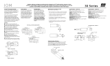
LED is O = Indicates the module is not correctly connected or receiving power.
LED is Green = Indicates the module is running without errors.
LED is Red = Indicates that one or more errors have been detected.
a
a

NXG-EAS Module
User Manual
For general module installaon instrucons, please refer to the NXG Base Plaorm User Manual.
Input/Output
Input
IP:
Addressing:
IP streams via NXG mainframe back plane
Multicast or Unicast
Output
IP: EAS IP streams via NXG mainframe back plane
Alarms/Monitoring
Front Panel Indicator: 1x Status LED
General
Dimensions:
(W x D x H)
1.15” x 15.5” x 7.0”
(29 mm x 394 mm x 178 mm)
Power: Via NXG Mainframe back plane
Power Consumption: 20 W
Weight: 2.0 lbs (0.9 kg)
Operating Temperature: 32 to 122 ˚F (0 to 50 ˚C)
Storage Temperature: -13 to 158 ˚F (-25 to 70 ˚C)
Operating Humidity: 0 to 95% RH @ 35 ˚C max,
non-condensing
Storage Humidity: 0 to 95% RH @ 35 ˚C max,
non-condensing

7NXG-EAS Module
User Manual
The “” tab (Figure 3) displays the general health and module informaon at a glance. The informaon is provided as
a quick way to monitor the module or assist with troubleshoong issues that may arise.
Indicates the current status of the module. Status Levels and colors shown below:
- No issues at the current me
Error - One or more errors have occurred. A short summary of the error message is shown under “Detected Issues”.
Check system log for more informaon on error(s).
Indicates the temperature of the module.
Indicates the length of me that the module has been running since the last reboot.
Indicates the model number of the module installed.
In the secon entled “” (Figure 3.1), the following parameters about the module health are displayed:
In the secon entled “”, the following module-specic informaon is indicated:
If any issues arise, the problem will be shown here and the color will correlate to the urgency of the issue. When there are no
issues, the text will say “No issues detected” and remain black text color. When there is an Error, then the text will change
to red and indicate what is causing the error (see Figure 3.2b)
1
2
2
3
4
1
2
3
4

8 NXG-EAS Module
User Manual
Indicates the serial number of the module installed.
Indicates the soware version of the module. To update soware, please see Secon 8.
Indicates the backplane rmware version for this module. Backplane version is only
needed for tech support and soware debugging.
Indicates the slot locaon on the plaorm chassis where the module is currently installed into.
Indicates the model number of the module installed.
In the secon entled “”, the following module-specic informaon is shown below:
The Tab allows a user to choose which available input programs to set up for EAS.
Clicking the small arrow ( collapsed; expanded) beside each program will show or hide further choices or read-
only data.
The “ ” column shows a list of all programs
available on the NXG plaorm available for EAS. The following
read-only informaon is shown:
Displays programs sourced from all
input modules within the NXG plaorm.
Displays the Source Stream Name and
bandwidth (Mb/s). An empty checkbox ( ) can be
checked ( ) to select one or more programs to be
added to the Output Transports column.
When the line is expanded, the following data ( ) for
each program is shown:
7-leer name for the channel.
Congures the MPEG Program used in all PSI tables for this stream. Range is 1 - 65,535.
1
1
2
2
3
4
5
1
2
3
5
4
1
2
3
4
5

NXG-EAS Module
User Manual
The user can click the selecon drop-down menu and choose between Output Streams and EAS
Stream.
Displays the available transport streams
le. As each program is added, the column number cks
downward.
Displays the combined bandwidth of the added
programs bitrate in MB/s.
The “ ” column provides controls to and
programs from the EAS Stream or Output Streams as well as
the following read-only informaon:
When one or more programs are selected from the “Available Inputs” column, pressing the Add buon will
immediately add the program(s) to the Output Transports column, indicang the program has been added
to the EAS Stream or Output Streams. The output programs are then automacally available to the other
modules for distribuon.
When one or more programs are selected from the “Output Transports” column, pressing the Remove
buon will immediately remove the program(s) from the Output Transports column, indicang the
program has been removed from the EAS Stream or Output Streams
Channel number assigned to a program within the Virtual Channel Table (VCT).
The bitrate is calculated over a period of me to give you the average bitrate of that program.
The peak bitrate consistently shows the maximum bitrate of that program.
Displays the module number that this channel is being sourced from. Numbered modules
correlate with what is currently installed and running in the NXG plaorm chassis.
The named assigned by the VCT to the program.
The “” column shows a list of all programs
have been added to the EAS Stream or Output Streams. The
following read-only informaon is shown:
Only programs which are being
encrypted will show up in this column.
Displays the Source Stream Name and
bandwidth (Mb/s). An empty checkbox ( ) can be
checked ( ) to select one or more programs to be
removed from the Output Transports column.
When the line is expanded, the following data ( ) for
each program is shown:
6
7
8
9
10
3
6
9
4
7
5
8
10
11
12

NXG-EAS Module
User Manual
The Tab allows a user to set up the EAS Trigger IP to be in the same subnet as the Monroe IP address and
allowing a way of tesng the EAS seng aer it is set up.
In the secon entled “” (Figure 5.1), the user can setup the following EAS trigger parameters:
Out-of-Band or Unicast IP Address from the EAS device (Trilithic, Monroe, etc).
Out-of-Band or Unicast Port from the EAS device.
the selecon of IGMP version between IGMPv2 and IGMPv3.
Source IPs for the EAS TS (when mulcast and IGMPv3 is enabled).
the codes used for this seng are in FIPS format.
the codes used for this seng are in FIPS format.
the codes used for this seng are in FIPS format.
1
4
2
5
7
3
6
1
2
3
5
6
7
4

NXG-EAS Module
User Manual
Save conguraon sengs.
Reboot the module.
Set IP address and subnet to be on the same subnet as the EAS Device (Trilithic, Monroe,
etc).
Aer conguring the EAS sengs, the user is able to test the EAS stream to ensure it works properly (ex: 172.16.70.88 and
port 5050). In order to test the EAS, the EAS stream be present.
Allows the user to Start the EAS Tesng.
Allows the user to End the EAS Tesng.
1
1
2
2
3
3 4
2 3
1

NXG-EAS Module
User Manual
Click this buon to reboot the module.
The Tab allows the user to manage the module conguraon through the following controls:
1 2
3 4
5
The “” secon allows the user to reboot the module from this screen.
5
Resets the module back to the Factory defaults. It is always recommended to save
the exisng conguraon le before reseng to the default values .
Downloads the current module conguraon le.
Browse and select a Conguraon File.
Aer choosing le, click this to load and apply the conguraon le.
The “” secon allows the user to back-up and re-load the conguraon sengs.
1
4
2
3

NXG-EAS Module
User Manual
Under the “” secon, the user can use and to select and send the module
update le(s) into the NXG Plaorm. See a view of the le when uploaded to the plaorm as shown below on Figure 7b.
Update the Firmware version by clicking the buon. The update status and progress will show under the
“” columns. Below are the rmware updates as they appear while in-progress (Figure 7c) and upon compleon
(Figure 7d). Aer the update is complete, the user reboot the module to nish applying the updates.
Aer clicking the “” buon, please allow a few seconds for the le to load.
The “Firmware Update” tab (Figures 7a, 7b, 7c, and 7d) is part of the Master Controller Module interface, and is used for all
installed modules. It is located on the right side of the main menu allowing the user to review currently installed rmware
versions and provides a quick and easy way to apply any new updates.
Check “” to ensure you have the latest rmware. To determine if a new rmware update has been
released, please go to our website at: (www.blondertongue.com/page/resources/tech-support/rmware-updates/)
Click the “Download Firmware Updates” link and then scroll down to the “NeXgen Gateway” folder to view the NXG
module folders.
: There is a check of the le name versus module ID to eliminate a user inadvertently updang any modules
with incorrect les. Mulple module updates can be performed simultaneously aer uploading the les.
Once the update progress is complete, the user click the buon (as shown on Figure 7d) in order to
apply and nalize the update.
1
4
2
3
3
4
2a 2b
1 3

NXG-EAS Module
User Manual
For technical support please contact us at 1-800-523-6049 between the hours of 8am and 5pm EST.
Please refer to the operaon manuals of each module for addional informaon.

NXG-EAS Module
User Manual
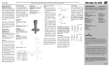
The EAS module (NeXgen) can be set up to work with your EAS unit in one of two modes: and .
Note: The EAS module can be used in USA and Canada. The Canadian operaons are all related to how to setup the Monroe
unit correctly for their correct region. The key feature is to translate the Standard Geographical Classicaon (SGC) codes
into exisng Federal Informaon Processing Standards FIPS code used in the United States. Refer to “Quick Start Guide One-
Net Canada” for detail seng up a Monroe unit for the Canadian market.
For tesng purposes, the user should ping both .188 and .88 address from a PC that is connected to 17 2.16.70.0/24. See the
Diagram below:
Power Supply
NeXgen System Outside NeXgen
QAM
IP In/Out
QAM Output Module
EAS Module IP Address
172.16.70.88
IP In/Out Module
Control Module
172.16.130.47
Switch
Input/Output stream and Input/Output stream and
EAS stream. Note trigger EAS stream. Note trigger
source is from Monroe unit source is from Monroe unit
below in Green.below in Green.
MonroeMonroe
172.16.70.188172.16.70.188
SCTE-18 EASSCTE-18 EAS
message sourcemessage source
Remote ControlRemote Control
172.16.130.200172.16.130.200
172.16.70.200172.16.70.200
Setup EAS module IP address to be in a same subnet as Monroe SCTE 18 trigger. For this example it is 172.16.70.88
• This is the path for the EAS trigger message to get to the EAS Module.
Setup the EAS unit's IP address to be in the same subnet at NeXgen EAS module. For this example a Monroe R189 unit
is setup at 172.16.70.188
Setup the EAS unit such that it can unicast to at 172.16.70.88
1
2
3

NXG-EAS Module
User Manual
Begin conguraon by selecng and adding programs to the TS Select tab (See Secon 4). Once the programs have been
added, click on the EAS Cong tab.
Set up the EAS trigger IP parameters to be in the same subnet as the Monroe IP address.
Use the EAS Test controls (see Secon 5) to ensure it is working properly. (ex: 172.16.70.88 and port 5050)
This funcon will only test the EAS stream, not the EAS trigger. The EAS stream MUST be present.
The “”, “”, “” and “” are all set on the Monroe unit.
The EAS Module values match the EAS system values in order to get the EAS message.
Here is an example of a real me message from a Monroe unit that contains two dierent State Codes below, “35” (New
Mexico) and “36” (New York) in this example. Because the EAS module is set to receive the “36” State Code, it will ignore
the State-Code “35”:
locaon_code_count: 2
state_code[0]: 35
county_subdivision[0]: 0
reserved6[0]: 3
county_code[0]: 0
state_code[1]: 36
county_subdivision[1]: 0
reserved6[1]: 3
county_code[1]: 0
excepon_count: 0
reserved11: 63
descriptors_length: 0
descriptors.oset[0]: 0
descriptors.length[0]: 0
descriptors.base[]:
CRC_32: 0x3584a9cf
=== Library Internal Variables ===
2
1
2
Set the EAS unit IP address mulcast (in this example it is 239.1.1.1 with correct port)
Set the EAS mulcast address group to same mulcast address (239.1.1.1)

NXG-EAS Module
User Manual
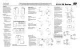
Please refer to the following GUI screen from Monroe. The example for New Mexico (035000) and New York (036000)
are the values generated by Monroe unit which must match with the EAS GUI (previous page): ,
, and .

NXG-EAS Module
User Manual
There are three clicks to get to the GUI screen (next page):
(Note the Monroe unit is very slow aer you click the Network and there is no vericaon that the user actually clicked.)
a) Setup
b) Network
c) Conguraon (SCTE-18)
Setup:Network:Conguraon:
Example: 172.16.70.188

NXG-EAS Module
User Manual
[172.16.70.188] IP Address
[255.255.255.0] IP Netmask
[Accept Changes/Restart Network]
Setup: Net Alerts: DVS644 (SCTE18)
There are three clicks to get to this GUI below:
Note the Monroe unit is very slow aer you click the Net Alert and there is no vericaon that the user actually clicked.
b) Setup b) Net Alerts c) DVS644 (SCTE-18)
c) Below enter the EAS IP address and port number (example: 172.16.70.88 port 5050 )

NXG-EAS Module
User Manual
[*970NE-EAS1-DCM1-HIPtv] Client Interface Name
[X] ENABLE Client Interface.
[172.16.70.88] Remote Host Unicast or Mulcast IP Address
[5050] Remote Host Port
[0] Mulcast TTL (0..200)
/