Megger DET3TD User manual

Type
User manual

This manual is also suitable for

M
DET3TA, DET3TC, DET3TD and DET4TD
Earth Ground Electrode Testers
USER MANUAL
GSAFETY WARNINGS
Safety Warnings and Precautions must be read and understood before the instrument is used. They must be observed during use.
Do not leave the instrument connected to the system under test when not in use.
Circuit connections and exposed metalwork of an installation or equipment under test must not be touched.
The instrument must not be operated or connected to any external system if it shows any visible signs of damage or if it has been stored for prolonged
periods in unfavourable conditions.
The instrument must not be operated or connected to any external system if the battery compartment or casing is open or any parts of the case
(including keypad, selector switch, display window, etc.) are missing.
The earth spikes, test leads and their terminations (including connections to the earthing system under test) must not be touched if an installation earth
fault can arise unless adequate precautions are taken.
The earth spikes, test leads and their terminations (including connections to the earthing system under test) must not be touched while the instrument
is switched on.
Special precautions are necessary when operating in situations where ‘live’ earths may be encountered: isolation switches and fuses (not supplied with
this instrument) must be used.
Special precautions are necessary when working near high tension systems (MV and HV): rubber gloves and shoes (not supplied with this instrument)
should be worn.
Special precautions are necessary when working in wet conditions or in agricultural areas: observe the local safety standards and take all necessary
special precautions applicable to the particular location.
The instrument must be disconnected from the earthing system under test while batteries are being changed or the fuse replaced.
Replacement batteries and fuses must be of the correct type and rating.
2
Users of this equipment and/or their employers are reminded that National Health and Safety Legislation requires them to carry out valid risk assessments of
all electrical work so as to identify potential sources of electrical danger and risk of electrical injury such as inadvertent short circuits. Where the assessments
show that the risk is significant then the use of fused test leads may be appropriate.
NOTE
THE INSTRUMENT MUST ONLY BE USED BY SUITABLY TRAINED AND COMPETENT PERSONS.
3
GLIVE EARTH SAFETY PRECAUTIONS
It is preferable that the earth electrode to be tested is first isolated from the circuit it is protecting, so that only the earth is measured and not the complete
system. When this is done, the circuits and equipment must be de-energised. If however this is not possible, the earth electrode should be duplicated so that
when it is disconnected for test purposes, the other one provides the necessary circuit protection. The following safety precautions are essential when
working near high tension systems where any unintentional ‘live’ earths may be encountered between the site earth and remote earths established for test
purposes. A ‘live’ earth is one that carries current from the mains supply, or could do so under fault conditions.
1. All persons involved must be trained and competent in isolation and safety procedures for the system to be worked on. They must be clearly instructed
not to touch the earth electrode, test spikes, test leads, or their terminations if any ‘live’ earths may be encountered. It is recommended that they wear
appropriate rubber gloves, rubber soled shoes, and stand on a rubber mat.
2. The ‘P’ (‘S’) and ‘C’ (‘H’) terminals should be connected through a double pole isolation switch, the rating of which will cope with the maximum fault
voltage and current. The isolation switch must be open whilst any personal contact is made with the remote test spikes, or the connecting leads, e.g.
when changing their position.
Note: If a fault occurs while a test is being made the instrument may be damaged. Incorporating fuses at the isolation switch, rated at 100 mA, and able to
cope with the maximum fault voltage will provide some protection for the instrument.
BATTERY INSTALLATION
Caution: Whenever battery cells are being fitted or replaced, there should be no connections to the instrument terminals. The cover to the battery
compartment lifts off the rear of the instrument and is held in position by a single captive screw in the base of the instrument. To fit or replace battery cells,
loosen the captive screw and lift away the cover. Fit new cells observing the correct polarity as indicated on the battery compartment moulding. Replace the
cover and tighten the securing screw. To avoid damage by leaking electrolyte, do not leave cells fitted in an instrument which will remain unused for
extended periods of time.
Symbols used on the instrument are:
G Caution: refer to accompanying notes
t Equipment protected throughout by Double
Insulation (Class II)
c Equipment complies with current EU directives.
Equipment complies with ‘C tick’ requirements
CONTENTS
4
Safety notices 2
Introduction 5
General description 5
Instrument illustrations 6
Preparations for use (all instruments) 8
General operating instructions (all instruments) 9
Replacing batteries and fuses 10
Megger’s ‘Down to Earth’ publication 11
Description of Tests for Models DET3TD, DET3TC and DET4TD 11
Battery 11
Measurement of ground noise voltage 11
Two-terminal resistance measurement 12
Three-terminal ground rod resistance measurement 12
Four-terminal ground rod resistance
measurement (DET4TD) 13
Ground resistance measurement (DET4TD) 13
Calibrating the instrument to the ICLAMP (DET3TC) 14
Measuring ground current with the ICLAMP (DET3TC) 14
Measuring ground resistance with the ICLAMP (DET3TC) 14
Attached Rod Technique (ART) (DET3TC) 15
Measuring ground resistance with the ICLAMP using the
ART (DET3TC) 15
Description of Tests for Model DET3TA 16
Battery-life reading 16
Ground noise voltage measurement 16
Two-terminal resistance measurement 17
Three-terminal resistance measurement 17
Preventative instrument maintenance 19
Technical specifications 19
Repair and Warranty 21
N1311
The Megger DET family of test instruments offers a unique solution to the
measurement of earth or ground electrode (rod) resistance and soil
resistivity. The family has three digital variants, which support 2, 3 and 4
point (DET4TD only) testing, and one analogue version that makes
provision for 2 and 3 point measurements.
The DET3TC can use an optional current clamp (ICLAMP) to measure
electrode (rod) resistance without disconnection, leaving the installation
earthing system intact (Attached Rod Technique, ART). The DET3TC in
conjunction with the current clamp can also measure conductor current.
The DET variants have the following features:
Feature DET3TA DET3TC DET3TD DET4TD
Automatic C spike check ■■
Automatic P spike check ■■
Manual P spike check
Automatic noise check ■■
Manual noise check
Noise rejection (40 V pk-pk) ■■
2-wire test ■■
3-wire test ■■
4-wire test
No disconnect testing (ART)
Voltmeter (ground noise
voltage measurement) ■■
INTRODUCTION GENERAL DESCRIPTION
5
Thank you for purchasing the Megger Earth Ground Electrode Tester.
For your own safety and to get the maximum benefit from your
instrument, please ensure that you read and understand the following
safety warnings and instructions before attempting to use the instruments.
This user manual describes the operation and functions of the DET series
of Earth Ground Electrode Testers:
DET3TA
DET3TC
DET3TD
DET4TD
DET3TA
INSTRUMENT ILLUSTRATIONS
6
Feature DET3TA DET3TC DET3TD DET4TD
Current measurement
LCD display
■■
Moving coil meter
IP54 rated ■■■
EN61010-1 100 V CATIV ■■■
Each instrument kit comprises instrument, test leads, test spikes, batteries
and calibration certificate stored in a tough polypropylene carrying-case.
Test lead connections
(at rear)
Rc OK
Selector switch
Resistance
measurement
settings (2P and
3P)
Resistance scale
Voltage scale
Potential test spike
resistance indicator
Battery charge indicator
Test lead connections (at rear of instrument)
Battery check setting and
voltage setting
Multi-function
analogue display
Test button
P Spike button
DET3TC DET3TD
7
Test lead connections
(at rear)
Resistance
measurement settings
(2P, 3P and clamp)
Selector switch
Voltage and current
measurement settings
Test button
Digital LCD display
Digital LCD display
Warning - refer to
User manual
Battery charge
indicator
Measuring range
Measuring range
Ruptured fuse
indicator
Over/under range
indicator
Potential probe
resistance indicator
(OK or high)
Current probe resistance
(OK or high)
Clamp current indicator
(OK or low)
Ground noise voltage
indicator (OK high)
Test lead connections (at rear of instrument)
Warning - refer to
User manual
Over/under range
indicator
Ruptured fuse
indicator
Potential probe
resistance indicator
(OK or high)
Current probe resistance
(OK or high)
Ground noise voltage
indicator (OK high)
Battery charge
indicator
Test lead connections
(at rear)
Resistance
measurement settings
(2P and 3P)
Selector switch
Voltage measurement
settings
Test button
8
Batteries
The Megger DET series instruments are supplied with batteries fitted.
When batteries become exhausted, refer to the section on battery
replacement.
Warning: Do not switch the instrument on with the battery cover
removed.
Inspection
Before each use of the instrument, visually inspect the instrument case,
test leads, spikes and connectors to confirm that their condition is good,
with no damaged or broken insulation.
DET4D
PREPARATIONS FOR USE (ALL INSTRUMENTS)
Test lead connections (at
rear of instrument)
Resistance measurement
settings (2P, 3P and 4P)
Selector switch
Voltage
measurement
settings
Test button
Warning - refer to
user manual
Ruptured fuse
indicator
Under/over
range indicator
Potential probe
resistance (OK or
high)
Test lead connection (at rear of instrument)
Current probe
resistance indicator
(OK or high)
Ground noise voltage
indicator (OK or high)
Measurement ranges
Battery charger
indicator
Digital LCD display
Instrument output voltage selection
The maximum output voltage of the instrument is nominally 50 V. Should
it prove necessary in particular circumstances, it is possible to set the
output voltage 25 V. The procedure for changing the output voltage is as
follows:
1. Press and hold the TEST button and switch instrument ON to the V
setting on the selector switch.
2. The LCD display will indicate ‘tst’ (DET3TC, DET3TD and DET4TD).
3. Release TEST button. The maximum output test voltage will be
displayed, either ‘50 V’ or ‘25 V’.
4. To toggle between the maximum output test voltages, press the TEST
button.
5. Switch off instrument when the desired maximum test voltage is
displayed.
Auto power down
To extend battery life the instrument will automatically switch off six
minutes after the last operation.
The instrument can be switched off manually by selecting the ‘OFF’ setting
on the selector switch and then switched on as normal.
Display symbols (DET3TC, DET3TD, DET4TD)
G Warning Triangle
f
Fuse Blown
Battery Indicator (not DET3TA).
>100V Indicates that the ground noise voltage exceeds the instrument
measurement capability.
Rp OK Potential spike (P Spike) is within range for accurate
measurement (<100 k).
9
Rp Hi Potential spike (P Spike) resistance exceeds range for accurate
measurement (>100 k).
Rc OK Current spike (C Spike) is within range for accurate
measurement (<100 k).
Rc Hi Current spike (C Spike) resistance exceeds range for accurate
measurement (>100 k).
Noise OK Ground noise voltage is within range for accurate measurement
(<40 Vpk-pk).
Noise Hi Ground noise voltage exceeds range for accurate measurement
(>40 Vpk-pk).
Display symbols (DET3TA)
Current spike (C Spike) is within range for accurate
measurement (<100 k).
Instrument is performing measurement checks.
Note:
Rc and Rp limit reduced to 50 k for 25 V output.
Rc and Rp limit reduced to 5 k on 18 range to achieve 0.01
resolution.
GENERAL OPERATING INSTRUCTIONS (ALL INSTRUMENTS)
Batteries
Battery type: 8 x LR6 (AA), 1.5 V Alkaline, or 8 x 1.2 V NiCAD, or 8 x
1.2V NiMH
The battery condition is continuously displayed by the bar-graph type
symbol (DET3TC, DET3TD and DET4TD) or by switching to the battery
setting and pressing the TEST button (DET3TA).
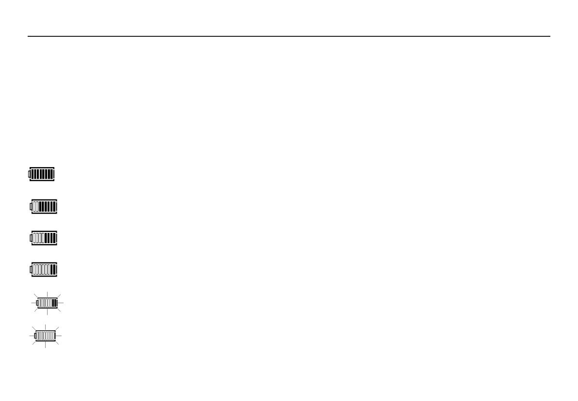
Figure 1 shows the progression of the battery indicator (for the DET3TC,
DET3TD and DET4TD) which gives a qualitative status of the battery charge
condition.
Fully charged battery
75% charged battery
50% charged battery
25% charged battery
Some testing still possible but battery may fail at any
time
Symbol flashes when there is not enough charge to
do a test and the instrument will turn itself off
Figure 1: Battery life indication (DET3TC, DET3TD, DET4TD)
REPLACING BATTERIES AND FUSES
Note: Fully charged NiMH or NiCAD rechargeable batteries show a lower
charge than alkaline batteries, and may not give much warning before
becoming exhausted
To replace batteries
Warning: Do not operate instrument with the battery cover removed.
1. To avoid the possibility of electric shock, switch instrument ‘OFF’ and
disconnect the instrument from any electrical circuits.
2. The rear cover must not be opened if the test leads are connected.
3. To avoid the possibility of electric shock, do not press the test button or
touch the fuse when changing batteries.
4. To remove the rear cover, release the screw at the bottom of the cover
and lift the cover upwards.
5. Remove the dead cells.
6. Refit new batteries observing the correct polarity as marked on the
battery compartment.
7. Replace the instrument back cover and secure by tightening the
retaining screw.
Warning: - Incorrect battery cell polarity can cause electrolyte leakage,
resulting in damage to the instrument. If the battery condition indicator
does not show a full charge when battery cells are new, a cell may be
reversed.
Note: Battery cells should not be left in an instrument that may remain
unused for extended periods.
Fuse
Fuse type: 500 mA (F), HBC, 50 kA, 600 V (32 x 6 mm)
10
11
The following descriptions of tests are a set of instructions for the sole
purpose of the proper use of these instruments by competent persons.
Where there is doubt about a particular application, reference should be
made to the advice and guidance contained within the publication ‘Down to
Earth’, available from Megger.
DESCRIPTION OF TESTS FOR MODELS DET3TC, DET3TD DET4TD
Battery
Before proceeding with measurements, ensure that the charge condition of
the batteries is sufficient to undertake the intended measurements. The
charge status is given in the bar-graph, as shown in Figure 1, which is
continually shown on the LCD when the instrument is switched on.
Measurement of ground noise voltage (DET3TC, DET3TD and
DET4TD)
Figure 2: Connections for measuring ground noise voltage and two-terminal
resistance.
Blown fuse symbol:
f
(DET3TD, DET3TC and DET4TD)
Only one fuse is contained within the instrument, and is user-replaceable.
When the fuse ruptures, symbol will show and testing is inhibited.
To replace the fuse
Warning: Do not operate instrument with the battery cover removed.
1. To avoid the possibility of electric shock, switch instrument ‘OFF’ and
disconnect the instrument from any electrical circuits.
2. The rear cover must not be opened if the test leads are connected.
3. To avoid the possibility of electric shock, do not press the test button
when replacing the fuse.
4. To remove the rear cover, release the screw at the bottom of the cover
and lift the cover upwards.
5. Disconnect the battery circuit before accessing the fuse.
6. Remove fuse and replace it with of fuse of the same characteristics.
7. Replace the instrument back cover and secure by tightening the
retaining screw.
MEGGER’S ‘DOWN TO EARTH’ PUBLICATION
Earth electrode
(rod) under test
Earth electrode
(rod) under test
Earth electrode
(rod) under test
Test spike
Test spike Test spike
12
4. A resistance reading will be displayed on the LCD display as shown in
Figure 4.
Figure 4: Two point resistance reading
Note: The test voltage used to make resistance measurements is a.c. and
because of this may not suitable for continuity testing in accordance with
local regulations.
Three-terminal ground rod resistance measurement (DET3TC,
DET3TD, DET4TD)
Figure 5: Connections for measuring three-terminal ground rod resistance
To measure the ground noise voltage:
1. With the selector switch set to the ‘OFF’position, connect the
instrument as shown in Figure 2.
2. Set the selector switch to the ground noise voltage setting marked ‘V’.
3. The ground noise voltage reading will be displayed on the LCD display
as shown in Figure 3.
Figure 3: Ground noise voltage reading
Two-terminal resistance measurement (DET3TC, DET3TD,
DET4TD)
1. With the selector switch in the ‘OFF’ position connect the instrument as
shown in Figure 2, but connected to the part of the installation you wish
to test
2. Set the selector switch to the 2 point resistance measurement setting
marked ‘2P’.
3. Press and release the TEST button [by pressing and holding the TEST
button, the resistance measurement will be continually updated and
displayed].
Earth electrode
(rod) under test
Earth electrode
(rod) under test
Earth
electrode
(rod)
under test
Current
spike
Current
spike
Current
spike
Potential
spike
Potential
spike
Potential
spike
DET4TD
1. With the selector switch in the ’OFF’ position, connect the instrument
as shown in Figure 5.
2. Set the selector switch to the 3 point resistance measurement setting
marked ‘3P’.
3. Press and release the TEST button [by pressing and holding the TEST
button, the resistance measurement will be continually updated and
displayed].
4. The instrument will then check for ground noise, the parameters of the
current and voltage circuits and the integrity of the fuse.
5. A resistance reading will be displayed on the LCD display, as shown in
Figure 6.
Figure 6: Three point resistance and four point resistivity reading
Four-terminal ground rod resistance measurement (DET4TD)
In circumstances where the lead resistance could introduce unacceptable
levels of error, the effect can be removed from the measured resistance
using the method below.
1. With the selector switch in the ‘OFF’ position, connect the instrument
as shown in Figure 5, with the lead shown dotted connecting terminal
‘C1’ to the earth electrode (rod) under test.
2. Set the selector switch to the 4 point resistance measurement setting
marked ‘4P’.
3. Press and release the TEST button [by pressing and holding the TEST
button, the resistance measurement will be continually updated and
displayed].
4. The instrument will then check for ground noise, the parameters of the
current and voltage circuits and the integrity of the fuse.
5. After a short period, a resistance measurement reading is displayed.
6. A resistance reading will be displayed on the LCD display, as shown in
Figure 6.
Ground resistance measurement (DET4TD)
Figure 7: Connections for measuring four-terminal soil resistance
Current
spike
Current
spike
Potential
spike
Potential
spike
13
8. The instrument is now calibrated to the particular ICLAMP.
9. Switch the instrument to the OFF position.
Measuring ground current with the ICLAMP (DET3TC)
Figure 8: Connections for measuring current using the current clamp
1. With the selector switch in the ‘OFF’ position, connect the instrument,
as shown in Figure 8 and close the ICLAMP around the earthing
conductor under test.
2. Turn the selector switch to the current measuring setting marked ‘A’.
3. The instrument will display a measured current value, as shown in
Figure 9.
14
Earth electrode
(rod) under test
Current clamp
Installation
earthing
conductor
1. With the selector switch in the ‘OFF’ position, connect the instrument as
shown in Figure 7.
2. Set the selector switch to the 4 point resistance measurement setting
marked ‘4P’.
3. Press and release the TEST button [by pressing and holding the TEST
button, the resistance measurement will be continually updated and
displayed].
4. The instrument will then check for ground noise, the parameters of the
current and voltage circuits and the integrity of the fuse
5. A resistance reading will be displayed on the LCD display, as shown in
Figure 6.
Calibrating the instrument to the ICLAMP (DET3TC)
Before proceeding with any measurement using the ICLAMP, it is essential
to calibrate the instrument to the particular ICLAMP using the following
procedure. This calibration should be repeated periodically.
1. With the selector switch in the ‘OFF’ position, connect ICLAMP to
instrument.
2. Press and hold the TEST button and switch instrument ON to the ‘A
setting on the selector switch.
3. Release TEST button,
4. Connect terminals ‘X’ and ‘C’ on the instrument together with the lead
provided with the ICLAMP.
5. Press and hold down the TEST button until a ‘0’ reading is obtained on
the instrument display.
6. Close clamp around the lead connecting the ‘X’ and ‘C’ terminals.
7. Press and hold the TEST button until a ‘100’ reading is obtained.
Figure 9: Current reading using the current clamp
15
Attached Rod Technique (ART) (DET3TC)
It is possible to use this instrument to measure the resistance of a ground
rod without disconnecting it from the rest of the system, thereby allowing
normal operations within the installation to continue uninterrupted. This
technique is known as the ‘Attached Rod Technique’ (ART). Where the
means of grounding comprises multiple rods, this technique also allows
individual measurement of each rod.
Measuring ground resistance with the ICLAMP using ART
(DET3TC)
Figure 10: Connection for measuring three-terminal ground rod resistance
1. With the selector switch in the ‘OFF’ position, connect the instrument,
as shown in Figure 10 and close the ICLAMP around the earthing
conductor under test.
2. Set the selector switch to the setting marked ‘3P ’.
3. Press and release the TEST button [by pressing and holding the TEST
button, the resistance measurement will be continually updated and
displayed].
Installation
earthing
conductor
Current
clamp
Potential
spike
Earth system
under test
Current
spike
16
Battery-life reading (DET3TA)
1.Set the selector switch to
2. Press and hold the TEST button.
3. The battery life will be indicated in the analogue display on the scale
marked with the , as shown in Figure 12.
4. Release TEST button.
Figure 12: Analogue display indicating remaining battery life
Ground noise voltage measurement (DET3TA)
Figure 13: Connections for measuring ground noise voltage and two-
terminal resistance
4. The instrument will then check for ground noise voltage, the
parameters of the current and voltage circuits and the integrity of the
fuse.
5. A resistance measurement reading is displayed as shown in Figure 11.
Figure 11: Three point resistance reading using ART
DESCRIPTION OF TESTS FOR MODEL (DET3TA)
Potential spike
Earth system
under test
Figure 15: Resistance reading between ‘X’ and ‘Y’ terminals
Three-terminal resistance measurement (DET3TA)
Figure 16: Connections for measuring three-terminal ground rod
resistance
1. With the selector switch in the ‘OFF’ position, connect the instrument
as shown in Figure 16.
2. Set the selector switch to the 3 point resistance measurement setting
marked ‘3P’.
3. The ground noise voltage is indicated on the analogue display.
4. If the ground noise voltage is within acceptable limits, push and hold
17
1. With the selector switch set to the ‘OFF’ position, connect the
instrument as shown in Figure 13.
2. Set the selector switch to the ground noise voltage setting marked ‘V’.
3. A voltage reading will be indicated on the analogue display, as shown in
Figure 14.
Figure 14: Analogue display indicating ground noise voltage measurement
Two-terminal resistance measurement (DET3TA)
1. With the selector switch in the ‘OFF’ position, connect the instrument
as shown in Figure 13, but connected to the part of the installation you
are testing.
2. Set the selector switch to the 2 point resistance measurement setting
marked ‘2P’.
3. The ground noise voltage is indicated on the analogue display
4. If the ground noise voltage is within acceptable limits, press and hold
down the TEST button.
5. The instrument will then check for ground noise voltage, the
parameters of the current and voltage circuits and the integrity of the
fuse during which time the Rc LED will flash.
6. A resistance reading will be indicated on the analogue display, as shown
in Figure 15.
7. Release TEST button.
Potential
spike
Current
spike
Earth system
under test
10. Continuous illumination of the Rc LED indicates that the resistance of
the current circuit is within limits.
11. A resistance reading will be indicated on the analogue display, as shown
in Figure 15.
12. On completion of measurement, release the TEST button.
18
down the ‘P Spike’ button.
5. A P Spike resistance reading will be indicated on the analogue display.
6. If the P Spike resistance is within acceptable limits as shown in Figure
17a (within the Green region on the Rp scale), release the ’Spike’
button.
Figure 17a: P Spike OK (in green zone)
Figure 17b: P Spike
NOT OK (in red zone)
7. Press and hold down the TEST button.
8. The instrument will then check for ground noise voltage, the
parameters of the current and voltage circuits and the integrity of the
fuse during which time the Rc LED will flash.
9. If the Rc LED fails to illuminate solidly and the needle does not move,
this may indicate that the fuse has blown or that the current probe
circuit (C Spike) resistance is out of limits.
1. The DET series instruments require very little maintenance.
2. Test leads should be checked before use to ensure there is no damage.
3. Ensure batteries are removed if left unused for extended periods.
4. When necessary, the instrument can be cleaned with a damp cloth.
5. Do not use alcohol-based cleaners, as these may leave a residue.
19
PREVENTIVE INSTRUMENT MAINTENANCE
General Specification
Only values with tolerances or limits are guaranteed data. Values without
tolerances are for information only.
Resistance Measurement
Range: 0.01 to 2,000
Accuracy: 2% ±3 digits (DET3TC, DET3TD, DET4TD)
2.5% of scale length (DET3TA)
Voltage Measurement
Range: 0 V to 100 V
Accuracy: 2% ±3 digits (DET3TC, DET3TD, DET4TD)
2.5% of scale length (DET3TA)
Current measurement (DET3TC only):
Range: 0.5 mA to 19.9 A
Accuracy: 5% ±3 digits
Temperature and Humidity
Operating Range: -15ºC to +55ºC
Storage Range: -40ºC to +70ºC
Environmental Protection: IP54
Safety
Meets the requirements of EN61010-1 100V CAT IV between terminal pairs.
EMC
In accordance with IEC61326 including amendment No.1
TECHNICAL SPECIFICATION
20
Power Supply
Dry cell: 8 x LR6 (AA), 1.5 V Alkaline
Rechargeable: 8 x 1.2V NiCAD, or 8 x 1.2V NiMH
Battery life: Approx. 700 consecutive tests
Fuses
500 mA (F), HBC, 50 kA, 600 V (32 x 6 mm)
Weight and Dimensions
Weight: 1kg (all units)
Dimensions: 203 x 148 x 78 mm (all units)
  • Page 1 1
  • Page 2 2
  • Page 3 3
  • Page 4 4
  • Page 5 5
  • Page 6 6
  • Page 7 7
  • Page 8 8
  • Page 9 9
  • Page 10 10
  • Page 11 11
  • Page 12 12
  • Page 13 13
  • Page 14 14
  • Page 15 15
  • Page 16 16
  • Page 17 17
  • Page 18 18
  • Page 19 19
  • Page 20 20
  • Page 21 21
  • Page 22 22

Megger DET3TD User manual

Type
User manual
This manual is also suitable for

Ask a question and I''ll find the answer in the document

Finding information in a document is now easier with AI