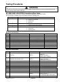
Maytag AGS1740BD series Specification
- Category
- Cookers
- Type
- Specification
This manual is also suitable for

16026293
May 2005
©2005 Maytag Services
This Base Manual covers general information
Refer to individual Technical Sheet
for information on specific models
This manual includes, but is
not limited to the following:
Service
This manual is to be used by qualified appliance
technicians only. Maytag does not assume any
responsibility for property damage or personal
injury for improper service procedures done by
an unqualified person.
AGS1740BD*
AGS3760BD*
AGS5830BD*
MGS5752BD*
MGS5775BD*
MGS5875BD*
Gas
Slide-In
Range

2 16026293 ©2005 Maytag Services
Pride and workmanship go into every product to provide our customers with quality products. It is possible, however,
that during its lifetime a product may require service. Products should be serviced only by a qualified service
technician who is familiar with the safety procedures required in the repair and who is equipped with the proper tools,
parts, testing instruments and the appropriate service information. IT IS THE TECHNICIANS RESPONSIBILITY TO
REVIEW ALL APPROPRIATE SERVICE INFORMATION BEFORE BEGINNING REPAIRS.
Important Notices for Servicers and Consumers
!
WARNING
To avoid risk of severe personal injury or death, disconnect power before working/servicing on appliance to avoid
electrical shock.
To locate an authorized servicer, please consult your telephone book or the dealer from whom you purchased this
product. For further assistance, please contact:
Customer Service Support Center
CAIR Center
Web Site Telephone Number
WWW.AMANA.COM................................................ 1-800-843-0304
WWW.MAYTAG.COM ............................................. 1-800-688-9000
CAIR Center in Canada ........................................... 1-800-688-2002
Amana Canada Product ........................................... 1-866-587-2002
Recognize Safety Symbols, Words, and Labels
DANGER!
DANGER—Immediate hazards which WILL result in severe personal injury or death.
WARNING!
WARNING—Hazards or unsafe practices which COULD result in severe personal injury or death.
CAUTION!
CAUTION—Hazards or unsafe practices which COULD result in minor personal injury, product or property
damage.
Important Information

©2005 Maytag Services 16026293 3
Table of Contents
Important Information ................................................... 2
Important Safety Information
What to Do if You Smell Gas ................................... 4
Safety Practices for Servicer .................................. 4
Servicing.................................................................. 4
Receiving Range ...................................................... 5
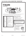
Using the Oven ......................................................... 5
Baking, Broiling, and Roasting ................................. 6
Connecting Range to Gas ........................................ 6
Electrical Requirements ........................................... 6
Extenstion Cord ....................................................... 6
Product Safety Devices ........................................... 6
General Information
Cooking Nomenclature ............................................. 7
Specifications .......................................................... 8
Placement of the Oven ............................................. 8
Do Not Block Air Vents ............................................ 8
Location of Model Number ........................................ 8
Model Identification .................................................. 8
Service ..................................................................... 8
Parts and Accessories ............................................. 8
Extended Service Plan ............................................. 8
Grounding ................................................................ 9
Range Description ................................................... 10
Troubleshooting Procedures ....................................... 11
Testing Procedures
Component Testing Procedures ............................. 14
M1 Oven Control Testing Procedures .................... 15
M1 Quick Test Mode .............................................. 16
M1 Description of Error Codes .............................. 17
M1 Notes ................................................................ 18
M2 Oven Control Testing Procedures .................... 18
M2 Quick Test Mode .............................................. 19
M2 Description of Error Codes .............................. 19
M2 Notes ................................................................ 21
H1 Oven Control Testing Procedures ..................... 22
H1 Relay Logic ...................................................... 23
H1 Quick Test Mode ............................................... 24
H1 Description of Error Codes .............................. 24
H1 Notes ................................................................ 26
Disassembly Procedures
Removing and Replacing Range ............................ 27
Surface Burner ...................................................... 27
Surface Burner Lower Assembly ........................... 27
Maintop Assembly .................................................. 27
Orifice Holder ........................................................ 27
Manifold and Top Burner ....................................... 27
Shut-off Valve ........................................................ 27
Regulator ............................................................... 27
Rocker Switch........................................................ 27
Bake Burner and Ignitor ........................................ 28
Broil Burner and Ignitor ......................................... 28
Surface Burner Gas Valve ..................................... 28
Back Panel ............................................................ 28
Control Panel ......................................................... 28
Electronic Control .................................................. 28
Oven Light Assembly ............................................. 29
Front Side Trim ...................................................... 29
Convection Element ............................................... 29
Convection Assembly ............................................ 29
Oven Sensor .......................................................... 29
Cooling Fan ........................................................... 30
Spark Module ......................................................... 30
Service Drawer ...................................................... 30
Hi-Limit Thermostat ................................................ 30
Door Plunger Light Switch ..................................... 30
Oven Door Latch/Door Light Switch Assembly....... 30
Oven Door Hinge ................................................... 30
Service Drawer Track Removal .............................. 30
Power Cord ........................................................... 31
Oven Door Removal ............................................... 31
Frameless Door Disassembly ................................ 31
Appendix A
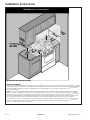
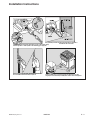
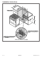
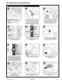
Installation Instructions .......................................... A-2
Appendix B
Use Information, AGS1740BD* ............................. B-2
Use Information, AGS3760BD* ............................. B-4
Use Information, AGS5830BD* ............................. B-6
Use Information, MGS5752BD* ............................ B-8
Use Information, MGS5775BD*, MGS5875BD* .. B-10
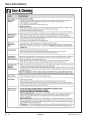
Care Information ................................................. B-12
Appendix C
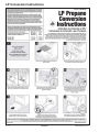
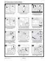
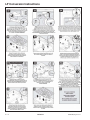
LP Conversion Instructions ...................................C-2

4 160226293 ©2005 Maytag Services
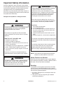
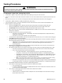
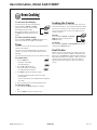
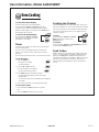
Important Safety Information
As with all appliances, there are certain rules to follow
for safe operation. Verify everyone who operates oven is
familiar with the operations and with these precautions.
Use appliance only for its intended purpose as
described. Pay close attention to the safety sections of
this manual. Recognize the safety section by looking for
the symbol or the word safety.
Recognize this symbol as a safety precaution.
!
WARNING
!
If the information in this manual is not followed exactly,
a fire or explosion may result causing property
damage, personal injury or death.
Do not store or use gasoline or other flammable
vapors and liquids in the vicinity of this or any other
appliance.
WHAT TO DO IF YOU SMELL GAS
• Extinguish any open flame.
• Do not try to light any appliance.
• Do not touch any electrical switch; do not use any
phone in your building.
• Immediately call your gas supplier from a neighbor’s
phone. Follow the gas supplier’s instructions.
• If you cannot reach your gas supplier, call the fire
department.
Installation and service must be performed by an
authorized installer, service agency or gas supplier.
WARNI NG
!
To avoid risk of electrical shock, property damage,
personal injury, or death, verify wiring is correct, if
components were replaced. Verify proper and
complete operation of unit after servicing.
WARNING
!
This gas appliance contains or produces a chemical
or chemicals which are known to the state of
California to cause cancer, birth defects, or other
reproductive harm. To reduce the risk from substances
in the fuel or from fuel combustion make sure this
appliance is installed, operated and maintained
according to the instructions in this manual.
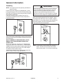
Due to the nature of cooking, fires can occur as a
result of overcooking or excessive grease. Although a
fire is unlikely, if one occurs proceed as follows:
Oven Fires
1. Do not open the oven door.
2. Turn all controls to OFF.
3. As an added precaution turn off the electricity at
the main circuit breaker or fuse box and the gas
at the main supply valve.
4. Allow the food or grease to burn itself out in the
oven.
If smoke or fire persists, call the local fire department.
To avoid the risk of property damage or personal injury
do not obstruct the flow of combustion or ventilation air
to the oven.
To avoid the risk of electrical shock, serious personal
injury or death: Make sure your range has been
properly grounded and always disconnect the
electrical and gas supply before servicing this unit.
NOTE: The maximum gas supply pressure for these
models must not exceed 14 inches W.C.P.
Safety Practices for Servicer
Safe and satisfactory operation of gas ranges depends
upon its design and proper installation. However, there is
one more area of safety to be considered:
Servicing
Listed below are some general precautions and safety
practices which should be followed in order to protect
the service technician and consumer during service and
after service has been completed.
1. Gas smell—Extinguish any and all open flames and
open windows.
2. Turn gas off—Service range with gas turned off
unless testing requires it.

©2005 Maytag Services 16026293 5
Important Safety Information
3. Checking for gas leaks—Never check for leaks with
any kind of open flame. Soap and water solution
should be used for this purpose. Apply solution to
suspected area and watch for air bubbles which
indicates a leak. Correct leaks by tightening fittings,
screws, connections, applying approved compound,
or installing new parts.
4. Using lights—Use a hand flashlight when servicing
ranges or checking for gas leaks. Electric switches
should not be operated where leaks are suspected.
This will avoid creating arcing or sparks which could
ignite the gas. If electric lights are already turned on,
they should not be turned off.
5. Do not smoke—Never smoke while servicing gas
ranges, especially when working on piping that
contains or has contained gas.
6. Check range when service is completed—After
servicing, make visual checks on electrical
connection, and check for gas leaks. Inform
consumer of the condition of range before leaving.
7. Adhere to all local regulations and codes when
performing service.
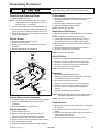
Receiving Range
• Installer needs to show consumer location and
operation of the range gas shut-off valve.
• Authorized servicer must install the range, in
accordance with the Installation Instructions.
Adjustments and service should be performed only by
an authorized servicer.
• Plug range into a 120–volt grounded outlet only. Do
not remove round grounding prong from the plug. If in
doubt about grounding of the home electrical system, it
is the consumers responsibility and obligation to have
an ungrounded outlet replaced with a properly
grounded three-prong outlet in accordance with the
National Electrical Code. Do not use an extension cord
with this appliance.
• Insure all packing materials are removed from the oven
cavity before operation, to prevent fire or smoke
damage should the packing material ignite.
• Ensure range is correctly adjusted by a qualified
service technician or installer for the type of gas
(Natural or LP). Some ranges can be converted for
use with Natural or LP gas.
• With prolonged use of a range, high floor
temperatures could result. Many floor coverings will
not be able to withstand this kind of use. Never install
range over vinyl tile or linoleum that cannot withstand
high temperatures. Never install range directly over
carpeting.
Using the Oven
• Do not leave children alone or unattended where a
range is hot or in operation. They could be seriously
burned.
• Do not allow anyone to climb, stand or hang on the
oven door. They could damage the range and cause
severe personal injury.
• Wear proper apparel. Loose fitting or hanging
garments should never be worn when using range.
Flammable material could ignite if brought in contact
with flame or hot oven surfaces which may cause
severe burns.
• Never use range for warming or heating a room. This
may cause burns, injuries or a fire.
• Do not use water on grease fires.
• Do not let grease or other flammable materials collect
in or around range.
• Do not repair or replace any part of range unless it is
recommended in this manual.
• Use only dry potholders. Moist or damp potholders
used on hot surfaces may result in a burn from steam.
Do not let a potholder touch the flame. Do not use a
towel or a bulky cloth as a potholder.
• Never leave range unattended while cooking. Boilovers
can cause smoking and may ignite.
• Only certain types of glass/ceramic, earthenware, or
other glazed utensils are suitable for oven use.
Unsuitable utensils may break due to sudden
temperature change.
• Use care when opening oven door. Let hot air or steam
escape before removing or replacing food.
• Do not heat unopened food containers in oven.
Build-up of pressure may cause a container to burst
and result in injury.
• Keep range vent ducts unobstructed.
• Place oven racks in desired location while oven is
cool. If a rack must be moved while oven is hot, use a
dry potholder.
• Do not use aluminum foil to line oven bottom or racks.
Aluminum foil can cause a fire, seriously affect baking
results, and damage to porcelain surfaces.
• Do not touch interior surfaces of oven during or
immediately after use. Do not let clothing or other
flammable materials come in contact with bake or broil
burners.
• Other areas of the oven can become hot enough to
cause burns, such as vent openings, window, oven
door and oven racks.
• To avoid steam burns, do not use a wet sponge or
cloth to wipe up spills on hot cooking area.
• Do not store combustible or flammable materials (such
as gasoline or other flammable vapors and liquids)
near or in oven.
• Do not clean oven door gasket located on back of the
door. Gasket is necessary to seal the oven and can be
damaged as a result of rubbing or being moved.
• Do not drape towels or any materials on oven door
handles. These items may ignite causing a fire.

6 160226293 ©2005 Maytag Services
Important Safety Information
CAUTION
!
Do not store items of interest to children in cabinets
above range. Children may climb on oven to reach
these items and become seriously injured.
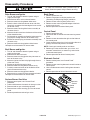
Baking, Broiling, and Roasting
• Do not use oven area for storage.
• Stand back from range when opening door of a hot
oven. Hot air or steam can cause burns to hands,
face, and eyes.
• Do not use aluminum foil anywhere in the oven. This
could result in a fire hazard and damage the range.
• Use only glass cookware appropriate for use in gas
ovens.
• Always remove broiler pan from oven when finished
broiling. Grease left in pan can catch fire if oven is
used without removing grease from the broiler pan.
• When broiling, meat that is close to the flame, may
ignite. Trim any excess fat to help prevent excessive
flare-ups.
• Make sure broiler pan is placed correctly to reduce
any possibility of grease fires.
• Should a grease fire occur in the broiler pan, turn off
oven, and keep oven door closed until fire burns out.
Connecting Range to Gas
Install manual shut-off valve in gas line for easy
accessibility outside range. Be aware of the location of
the shut-off valve.
Electrical Requirements
120-volt, 60 Hertz, 20 amp, individual circuit which is
properly grounded, polarized and protected by a circuit
breaker or fuse.
Extension Cord
Do not use extension cords with this product.
Product Safety Devices
Safety devices and features have been engineered into
the product to protect consumer and servicer. Safety
devices must never be removed, bypassed, or altered in
such a manner as to defeat the purpose for which they
were intended.
Listed below are various safety devices together with the
reason each device is incorporated in the gas ranges.
Pressure Regulator Maintains proper and
steady gas pressure for
operation of oven
controls.
Regulator must be set
for the type of gas being
used Natural or LP.
After servicing regulator,
make certain it is set
properly before
completing service.
Gas Burner Orifices Universal orifices are
used on most valves.
They must be adjusted
for the type of gas being
used Natural
or LP.
After servicing a valve
or orifice verify it is
adjusted properly before
completing service.
Oven Safety Valve Oven valve is designed
to be a safety valve. Two
basic designs are used
in gas ranges:
Hydraulic and Electric
Both types are safety
valves because they are
indirectly operated by
the oven thermostat,
which controls a pilot
flame or electric ignitor,
to open and close the
oven valve.
Grounded Oven Frame Ground prong on power
cord is connected to the
frame, usually a green
lead fastened by a
screw. In addition, any
part or component
capable of conducting
an electric current is
grounded by its
mounting.
If any ground wire,
screw, strap, nut, etc. is
removed for service, or
any reason, it must be
reconnected to its
original position with
original fastener before
the appliance is put into
operation again.
Failure to do so can
create a possible shock
hazard.

©2005 Maytag Services 16026293 7
This manual contains information needed by authorized
service technicians to install and service gas ranges.
There may be, however, some parts which need further
explanation. Refer to the Installation Instructions, Use
and Care, Technical Sheets or the toll-free technical
support line.
This manual provides basic instructions and suggestions
for handling, installing and servicing gas ranges.
The directions, information, and warnings in this manual
are developed from experience with, and careful testing
of the product. If the unit is installed according to this
manual, it will operate properly and will require minimal
servicing. A unit in proper operating order ensures the
consumer all the benefits provided by clean, modern gas
cooking.
General Information
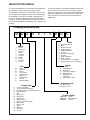
Cooking Nomenclature
M G S 5 8 7 5 B D S
Brand
A Amana
C Magic Chef
G Graffer &
Sattler
H Hardwick
J Jenn-Air
M Maytag
N Norge
U Universal
Y Crosley
Product Type
A Accessory/Cartridge
C Cooktop Updraft/Countertop
D Downdraft Cooktop or Warming Drawer
E Eyelevel Range
G Grill
L Range (20")
M Range (36")
P Drop In (24")
Q Wall Oven (27")
R Range, Free-Standing (30")
S Slide-In (30")
T Range Hood
V OTR
W Wall Oven
Y RV Range
Z RV Top
Fuel
B Butane
D Dual Fuel
E/J Electric
G Gas, Natural
L Liquid Propane
M Microwave
P Standing Pilot
X No Fuel
W Warming Drawer
Listing
A UL/AGA
C CSA/CGA/CUL
D Dual Listed
G 220-240 V / 50-60 Hz
M Military Model
P PSB Approved
(Singapore)
X Export 120 V / 60 Hz
Feature Content
1000-3999 Brands
4000-6999 Maytag/Amana
7000-9999 Jenn Air
Production Code
This identifies the
production version.
Color
A Almond on Almond
B Black
C Brushed Chrome
H Traditional White
L Traditional Almond
P Prostyle
Q Monochromatic Bisque
S Stainless
T Traditional Bisque
W White on White
F Frost White (True Color White)
N Natural Bisque (True Color Bisque)

8 16026293 ©2005 Maytag Services
Specifications
Refer to individual Technical Sheet for specification
information.
Placement of the Oven
This freestanding range must be placed in the kitchen or
comparable room. All safety guidelines must be followed
and free air flow around the range is essential.
Do Not Block Air Vents
All air vents must be kept clear during cooking. If air
vents are covered during operation, the oven may
overheat. If this occurs, a sensitive, thermal safety device
automatically removes power to the oven, rendering the
oven inoperable. The oven will remain in this state until it
has sufficiently cooled.
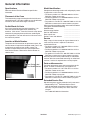
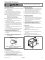
Location of Model Number
To request service information or replacement parts, the
service center will require the complete model, serial, and
manufacturing number of your slide-in range. The
number can be found on the oven chassis behind the
front Service Drawer. Remove the Service Drawer to
view the data.
Model Number
Rating Label
General Information
Model Identification
Complete enclosed registration card and promptly return.
If registration card is missing:
• For Amana product call 1-800-843-0304 or visit the
Web Site at www.amana.com
• For Maytag product call 1-800-688-9900 or visit the
Web Site at www.maytag.com
• For product in Canada call 1-866-587-2002 or visit the
Web Sites at www.amana.com or www.maytag.com
When contacting provide product information located on
rating plate. Record the following:
Model Number: ___________________
Manufacturing Number: ___________________
Serial or S/N Number: ___________________
Date of purchase: ___________________
Dealer’s name and address: ___________________
Service
Keep a copy of sales receipt for future reference or in
case warranty service is required. To locate an
authorized servicer:
• For Amana product call 1-800-628-5782 or visit the
Web Site at www.amana.com
• For Maytag product call 1-800-462-9824 or visit the
Web Site at www.maytag.com
• For product inCanada call 1-866-587-2002 or visit the
Web Sites at www.amana.com or www.maytag.com
Warranty service must be performed by an authorized
servicer. We also recommend contacting an authorized
servicer, if service is required after warranty expires.
Parts and Accessories
Purchase replacement parts and accessories over the
phone. To order accessories for your product call:
• For Amana product call 1-877-232-6771 or visit the
Web Site at www.amana.com
• For Maytag product call 1-800-688-9900 or visit the
Web Site at www.maytag.com
• For product in Canada call 1-866-587-2002 or visit the
Web Sites at www.amana.com or www.maytag.com
Extended Service Plan
We offer long-term service protection for this new oven.
• Dependability Plus
SM
Extended Service Plan is
specially designed to supplement Maytag’s strong
warranty. This plan covers parts, labor, and travel
charges.
Call 1-800-925-2020 for information.

©2005 Maytag Services 16026293 9
General Information
Grounding
NOTE: This appliance must be properly grounded, for
personal safety.
Power cord on this appliance is equipped with a three-
prong grounding plug. This matches standard three-prong
grounding wall receptacle to prevent possibility of electric
shock from this appliance.
Consumer should have wall receptacle and circuit
checked by qualified electrician to verify receptacle is
properly grounded.
It is the consumers responsibility to replace standard two-
prong wall receptacles with properly grounded three-prong
wall receptacles.
DO NOT, UNDER ANY CIRCUMSTANCES, CUT OR
REMOVE THE THIRD (GROUND) PRONG FROM
POWER CORD.
For 15 amp circuits only, do not use an adapter on 20
amp circuit. Where local codes permit, a TEMPORARY
CONNECTION may be made to a properly grounded two-
prong wall receptacle by the use of a UL listed adapter
(available at most hardware stores).
Larger slot on adapter must be aligned with larger slot in
the wall receptacle to provide proper polarity.
WARNING
!
Attaching adapter ground terminal to wall receptacle
cover screw does not ground appliance unless the
cover screw is metal and not insulated, and wall
receptacle is grounded through the house wiring.
Consumer should have circuit checked by a qualified
electrician to verify receptacle is properly grounded.
When disconnecting power cord from adapter, always
hold adapter with one hand. If this is not done, adapter
ground terminal is very likely to break with repeated use.
Should this happen, DO NOT USE appliance until a
proper ground has been established.
Neutral Wire
Hot Line
Ground
NOTE: Circuit tester can be used to verify voltage at
outlet. Connect one lead to hot line and the
other lead to ground. Circuit tester should light.

10 16026293 ©2005 Maytag Services
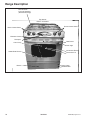
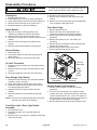
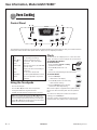
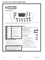
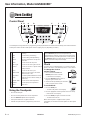
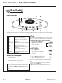
Range Description
Broil Burner
Hidden Bake Burner
Drawer
Convection Fan
Shut-off Valve/
Pressure Regulator
(Backside of Range)
Electronic Control
Touchpad
Top Surface
Burners and Grates
Oven Light
Model Number
Rating Label
Burner Control Valves
Burner Control Valves
Oven Cavity
Convection Element

Troubleshooting Procedures
!
WARNING
To avoid risk of electrical shock, personal injury, or death, disconnect power and gas to range before servicing,
unless testing requires power and/or gas.
©2005 Maytag Services 16026293 11
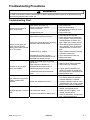
Troubleshooting Chart
Problem Possible Cause Correction
Burners will not ignite; no
spark at top burner.
Poor ground on burner cap ......................
.
Weak or failed spark module....................
.
Low gas pressure .....................................
.
Clogged burner port .................................
.
• Clean burner cap.
• Replace spark module.
• Verify pressure 4" WCP for natural,
10" WCP for LP.
• Clean burner cap.
Burner will not ignite. No
spark to burner ignitors
when burner knob is rotated
to "LITE" position.
No 120 VAC to range ...............................
.
Micro switch contacts not closing.............
.
Faulty wiring. Bad connection at burner
electrode and electrode socket ................
.
Inoperative spark module.........................
.
Electrode dirty. Burner cap dirty...............
.
Cracked or broken electrode or socket ....
.
Electrode wire broken or loose.................
.
• Verify voltage at wall outlet.
• Check wiring against appropriate
wiring diagram. Verify all terminals
and connections are correct and
tight. Check micro switch contacts.
• Check wiring against appropriate
wiring diagram. Verify all terminals
and connections are correct and
tight.
• Check module according to testing
procedures information.
• Clean electrode or burner cap.
• Replace electrode.
• Reconnect/replace wire.
No spark or only random
spark at one ignitor.
Check for cracked ignitor or pinched
ignitor wire ...............................................
.
Poor continuity to burner cap ...................
.
Bad ground connection or lack of
continuity to ground or ignitor...................
.
Cracked or broken ignitor extension
lead...........................................................
.
• Replace ignitor lead or electrode.
• Clean burner cap and lead.
• Tighten ground connection and
correct any breaks in ground path
from ignitor path to unit ground path.
• Replace ignitor lead.
Unit continues to spark after
knob is turned to OFF
position.
Shorted valve switch/harness ..................
.
Switch has slipped off the valve ...............
.
• Replace switch/harness. If shorting
is caused by excessive spillovers,
customer education is advised.
• Carefully reposition switch on valve
and rotate from OFF to high, several
times to verify switch is not broken.
No oven operation in bake or
broil.
No voltage to control. ...............................
.
No voltage from control ............................
.
Loose wire connection or broken wire......
.
• Check for 120 VAC at control. If no
voltage, check power source.
• Check 120 VAC to ignitor. If no
voltage, replace control.
• Verify all connections are clean and
tight. Replace broken wire.

Troubleshooting Procedures
!
WARNING
To avoid risk of electrical shock, personal injury, or death, disconnect power and gas to range before servicing,
unless testing requires power and/or gas.
12 16026293
©2005 Maytag Services
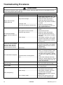
Problem Possible Cause Correction
No gas flows to burner.
Ignitor glows red.
Failed ignitor. ..........................................
.
Gas pressure too high ............................
.
Failed gas valve .....................................
.
Loose wire connection or broken wire....
.
• Check ignitor current draw, 3.2 – 3.6
Amps. Replace ignitor, if it fails test.
• Check for correct gas pressure.
Natural gas pressure should be 4"
WCP and LP gas pressure should be
10" WCP.
• Check gas valve for continuity.
• Verify all connections are clean and
tight, replace broken wire.
Gas flows to bake/broil
burner, but burner does not
light.
Ignitor positioned too far from burner .....
.
Dirt or grease in orifice or burner ...........
.
Insufficient gas pressure ........................
.
Power outage .........................................
.
• Reposition ignitor closer to bake/broil
burner.
• Clean orifice or burner.
• Check for correct gas pressure.
Natural gas pressure should be 5"
WCP and LP gas pressure should be
10" WCP.
• Verify power is present at unit. Verify
that the circuit breaker is not tripped.
• Replace household fuse, but do not
fuse capacity.
Broil burner shuts off shortly
after the start of self-clean
operation. Bake and broil
functions operate normally.
Power outage .........................................
.
Control Error...........................................
.
• Verify power is present at unit. Verify
that the circuit breaker is not tripped.
• Replace household fuse, but do not
fuse capacity.
• Replace control.
Fan motor does not operate.
No power to fan motor............................
.
Failed fan motor or winding/frozen
shaft........................................................
.
• Check for 120 VAC supplied at fan
motor. If no voltage is present, check
for broken or loose wiring between
fan motor and relay board. If voltage
is present at fan motor, go to the next
step.
• Check motor winding for continuity.
Check for a frozen motor shaft. Check
for broken wiring between motor and
neutral terminal block.
Oven smokes/odor first few
times of usage.
Normal....................................................
.
• Minor smoking and/or odor is normal
the first few times of oven usage.
Failure Codes.
Electronically Controlled.........................
.
• See the applicable "Fault Code Chart"
in Testing section.
Oven not operating.
Programming error .................................
.
Power outage .........................................
.
Unit in Sabbath mode.............................
.
• Switch circuit breaker off to oven for
five minutes and try oven again.
• Verify power is present at unit and
circuit breaker is not tripped.
• Replace household fuse, but do not
fuse capacity.
• Refer to Use & Care manual and
remove unit from Sabbath mode.

Troubleshooting Procedures
!
WARNING
To avoid risk of electrical shock, personal injury, or death, disconnect power and gas to range before servicing,
unless testing requires power and/or gas.
©2005 Maytag Services 16026293 13
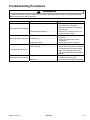
Problem Possible Cause Correction
Clock and timer not working.
Power outage ..........................................
Electronic Control locked ........................
• Verify power is present at unit and
circuit breaker is not tripped.
• Replace household fuse, but do not
fuse capacity.
• Refer to Use and Care manual and
unlock electronic control.
Oven light does not operate.
Failed oven lamp .....................................
Failed wiring ............................................
Failed light socket....................................
• Check lamp and replace is
necessary.
• Check for broken, loose or dirty
connections.
• Check light socket for continuity.
Oven door will not unlock.
Oven is self-cleaning...............................
Oven is still hot ........................................
• Allow cycle to complete.
• Will not unlock until unit has cooled to
safe temperature. Do not force door
open, this will void warranty. Blow
cool air on door latch area to quicken
process.
Self-clean cycle not working.
Programming error ..................................
Door lock .................................................
• Turn off circuit breaker for five
minutes and try oven again.
• Verify door lock energizes & engages.

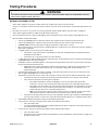
Testing Procedures
!
WARNING
To avoid risk of electrical shock, personal injury or death; disconnect power and gas to range before servicing,
unless testing requires power and/or gas.
14 16026293
©2005 Maytag Services
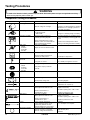
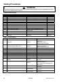
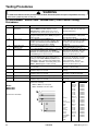
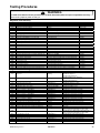
Component Testing Procedures
Illustration Component Test Procedure Results
Oven light socket Test continuity of receptacle terminals....
Measure voltage at oven light.................
Indicates continuity with bulb screwed in.
120 VAC; see wiring diagram for terminal
identification. If no voltage is present at
oven light check wiring.
Door plunger switch Remove switch from unit and measure
the following points:
COM to NO ........................................
Plunger in continuity, plunger out infinity.
Autolatch assembly Disconnect wires and test for
continuity per wiring diagram.
Refer to Parts Manual for correct
autolatch switch associated with the
correct manufacturing number.
See wiring diagram for schematic layout.
Access assembly by removing right side
panel.
Common is in neutral position unless
locking or unlocking autolatch assembly.
270° valve
5 K btu
9.2 K btu
12.5 K btu
16 K btu
Verify gas is supplied.
Adjust set screw for simmer control.
Spark 270° switch Test for voltage at terminals ..................
Disconnect wiring and check for
continuity in LITE position......................
120 VAC
Continuity in LITE position.
Spark ignition
electrode
Test for resistance of spark lead............
Test ignitor to chassis............................
Continuity
No continuity from ignitor to chassis.
Top surface burner
5 K btu
9.2 K btu
12.5 K btu
16 K btu
Verify gas is supplied.............................
Verify burner cap is positioned
correctly.
Check for obstructions in burner ports.
Top surface burner cap Verify cap is positioned correctly ........... Check for obstructions in burner ports.
L
AB
A1
B1N
Spark module 4 + 0 Test for voltage at terminals L and N.....
Check polarity and ground.....................
120 VAC (tolerance: 102 to 132 VAC)
See wiring diagram
Temperature sensor Measure resistance ...............................
Approximately 1000 Ω at room
temperature 75° F (23.8° C).
Broil burner Verify gas is supplied.
Orifice adjusted for Natural or LP ..........
Check for obstructions or
contamination in ports ...........................
Factory set to Natural Gas.
Adjust as necessary.
Air shutter opening set to .281 to .343.
Replace if punctured or torn.
Bake burner Verify gas is supplied.
Orifice adjusted for Natural or LP ..........
Check for obstructions or
contamination in ports ...........................
Factory set to Natural Gas.
Adjust as necessary.
Air shutter opening set to .469 to .531.
Replace if punctured or torn.
Ignitor Test for voltage at terminals ..................
Test for amperage in the circuit .............
(Ignitor may glow but not have
sufficient amperage to open valve.)
120 VAC.
3.2 − 3.6 Amps. If not, replace.
Convection element Disconnect wiring to element and
measure resistance of terminals............
Measure voltage at broil element...........
Approximately 30 Ω.
240 VAC.

Testing Procedures
!
WARNING
To avoid risk of electrical shock, personal injury or death; disconnect power and gas to range before servicing,
unless testing requires power and/or gas.
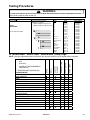
©2005 Maytag Services 16026293 15
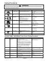
Illustration Component Test Procedure Results
Convection assembly
Convection motor
Measure voltage ........................................
Check motor windings to ground................
120 VAC. (tolerance: 105 to 135 VAC)
No continuity.
RPM: Approx. 900 (tolerance: 700 to
1100 RPM).
Hi-limit temperature
switch
Normally closed, verify operation:
Open: 249° to 271°F (121° to 133°C) .......
Closed: 173° to 207°F (78° to 97°C).........
Infinite.
Continuity.
Double thermal valve/
shut off valve
Verify gas supply is turned on at
regulator.....................................................
Disconnect wiring to valve.
Measure bake circuit resistance.................
Measure broil circuit resistance..................
Gas is supplied.
Continuity.
Continuity.
Pressure regulator Verify gas pressure (W.C.P.). ....................
If on LP service verify proper gas supply
conversion.
5" Natural
10" LP/propane
Gas ON Tab up.
Gas OFF Tab down.
Cooling fan motor Measure voltage ........................................
Check motor windings to ground................
120 VAC.
No continuity.
RPM: 1670 to 2070
Orifice holder Verify gas pressure....................................
Check orifice for debris ..............................
5" Natural
10" LP/propane
Clean as needed.
Rocker switch Measure continuity of switch positions:
Closed ....................................................
Open ......................................................
Continuity
Infinite
Power cord 3-wire Verify resistance of wires to terminals........ Continuity.
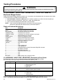
M1 (AGS1740BD*, MGS5752BD*) Oven Control Testing Procedures
Control Component Test Procedure Results
M1 Controlled Oven temperature
adjustment
Press
BAKE
pad.
Enter
550
on the digit-pad.
Immediately press and hold
BAKE
pad for 3
seconds.
Oven can be adjusted from -35 to +35 degrees
in 5-degree increments by pressing
(Up Arrow)
or
(Down Arrow)
pads. To avoid over adjusting
the oven, move temperature 5 degrees each
time. Wait 4 seconds for the data entry timer to
expire to accept the change. Temperature
adjustment will be retained even through a
power failure.
Increasing or decreasing oven
temperature does not affect self-
cleaning temperature.
M1 Controlled Temperature display Press and hold
CANCEL
and
BAKE
pads for 5
seconds. Press
(Up Arrow)
or
(Down Arrow)
pads to change.
This mode enables the user to
indicate °F or °C on the display.
M1 Controlled Clock Display Press and hold
CANCEL
and
CLOCK
pads for
5 seconds.
Allows clock to be toggled On or
OFF.
M1 Controlled 24 Hour Clock Press and hold
CANCEL
and
DELAY
pads for 5
seconds. Press
(Up Arrow)
or
(Down Arrow)
pads to change.
Allows the time on the clock to be
toggled from 12 hour or 24 hour
display.
M1 Controlled Factory Default Press and hold
CANCEL
and
KEEP WARM
pads for 5 seconds.
Allows the clock to be reset to factory
settings.
M1 Controlled Twelve hour off Control automatically cancels cooking operation
and removes all relay drives 12 hours after the
last pad touch.
See Sabbath mode to disable.

Testing Procedures
!
WARNING
To avoid risk of electrical shock, personal injury or death; disconnect power and gas to range before servicing,
unless testing requires power and/or gas.
16 16026293
©2005 Maytag Services
Control Component Test Procedure Results
M1 Controlled Sabbath Mode Hold
CLOCK
pad for 5 seconds to
activate Sabbath mode.
Hold
CLOCK
pad for 5 seconds to
disable Sabbath mode.
Desired bake function must be initiated
before entering Sabbath mode.
"SAb" will flash for 5 seconds, then remain on until
timed-out or cancelled.
The status SAB is not fault code 5AB.
All pad inputs are disabled except for
CANCEL
and
CLOCK
pads.
This mode disables the normal 12 hour shutoff to
allow operation of the bake mode for a maximum of
72 hours.
The oven light is not disabled.
M1 Controlled Child lock out Press and hold
CANCEL
and
COOK
& HOLD
pads for 3 to 5 seconds until
beep sounds.
To reactivate the control, press and
hold
CANCEL
and
COOK & HOLD
pads
for 5 seconds.
This is a safety feature that can be used to prevent
children from accidentally programming the oven. It
disables the electronic oven control.
Child lockout features must be reset after a power
failure.
M1 Controlled Diagnostic Code
Display
Press and hold
(Up Arrow)
pad
within 60 seconds of powering up
the unit.
Cycle through the codes using the
(Up Arrow)
or
(Down Arrow)
pads.
The last 5 diagnostic codes will be stored in the non-
volatile memory.
See
"Description of Error Codes" for explanation.
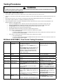
M1 (AGS1740BD*, MGS5752BD*) "Quick Test" Mode for Electronic Range
Control
Follow procedure below to use the quick test mode. Entries must be made within 32 seconds of each other or the
control will exit the quick test mode.
1. Press and hold
CANCEL
and
BROIL
pads for 5 seconds.
2. Once the control has entered the "Quick Test" mode, release both pads.
3. Press each of the following pads indicated in the table below.
NOTE: First time one of the following pads is pressed, it activates the response.
The second time the pad is pressed, it deactivates the response.
NOTE: This mode can only be entered within the first 5 minutes of power up.
NOTE: If the temperature sensor is greater than 400° F or if the temperature sensor reaches 400° F while
under test, the Quick Test mode will be disabled.
Display will indicate the following:
Key Operation
[Bake]
Bake relay activated
[Broil]
Broil relay activated
[Keep Warm]
DLB relay activated
[Cook&Hold] Last Diagnostic Code displayed
[Clean] Beep sounds
[Delay] (M1)
EEPROM Version Number displayed
[Timer]
Main Code Version Number displayed
[Clock]
All Segments On
[Up Arrow]
Even Segments On
[Down Arrow]
Odd Segments On
[Cancel] End Factory Test Mode

Testing Procedures
!
WARNING
To avoid risk of electrical shock, personal injury or death; disconnect power and gas to range before servicing,
unless testing requires power and/or gas.
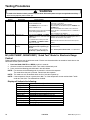
©2005 Maytag Services 16026293 17
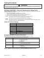
M1 (AGS1740BD*, MGS5752BD*) Description of Error Codes
Error diagnostic codes can only be viewed by entering the Diagnostic Code Display Mode.
Each error code is four digits long and created based on the following table.
Digit Description
1
st
Primary System: 1 – Local to the control circuit board
3 – Sensor or meat probe
4 – Control input
9 – Door lock
2
nd
Measurable: d – Diagnostic: measurable parameter
c – Control related, replace control
3
rd
Secondary System: Sequential numbering
4
th
Oven Cavity: 1 – Upper oven (or single cavity oven)
2 – Lower oven
c – Control specific
Diagnostic Code Display Mode can only be started within 30 seconds when powering up the control.
Diagnostic Code Checking
Code Description When Checked Detection
1c1c Shorted key Always 1 minute
1c2c Keyboard tail disconnected Always 1 minute
1c31 Cancel key circuit problem Always 20 seconds
1c6c EEPROM error When accessing EEPROM 3 tries
1c7c Control not calibrated Always 3 tries
1c8c Cooking program error Cook or clean programmed 3 tries
1d11 Runaway temp (650°F), door unlocked Latch unlocked 1 minute
1d21 Runaway temp (950°F), door locked Latch locked 1 minute
3d11 Sensor open Cook or clean active 20 seconds
3d21 Sensor shorted Cook or clean active 20 seconds
9d11 Latch will not lock Latch should be locked See Note
6
Diagnostic Code Handling
Code Measurable What is Displayed Action Taken By Control
1c1c Keypress Nothing
Disables audible for affected key
depression
Disables all outputs
1, 2
Disables lights and timers
1c2c Keyboard loop improper value Nothing
Disables audible for key depression
Disables all outputs
1
Disables lights and timers
1c31 Cancel key improper value BAKE flashes
3
Disables all outputs for cavity
1
1c6c No response from EEPROM Nothing Disables all outputs
1
1c7c Calibration value out of range "CAL" in time digits Completely disables oven
4
1c8c CRC invalid Nothing Cancels active cook functions
1d11 Sensor resistance > 2237 Ohms BAKE flashes
3
Disables all cook functions for cavity
1d21 Sensor resistance > 2787 Ohms BAKE flashes
3
Disables all cook functions for cavity
3d11 Sensor resistance > Infinite Ohms BAKE flashes
3
Disables all cook functions for cavity
3d21 Sensor resistance > 0 Ohms BAKE flashes
3
Disables all cook functions for cavity
4d11 Door switch not closed when door locked Nothing Disables Clean & Lockout functions
5
4d51 Door switch not open or closed
Nothing
Disables Convect, Clean, and
Lockout functions
4, 5
Turn off/disable light at door switch
9d11 Lock switch not closed LOCK flashes
3
Disables Clean & Lockout functions
5

Testing Procedures
!
WARNING
To avoid risk of electrical shock, personal injury or death; disconnect power and gas to range before servicing,
unless testing requires power and/or gas.
18 16026293
©2005 Maytag Services
M1 (AGS1740BD*, MGS5752BD*) NOTES:
1
"Action Taken" applies as long as the condition exists. If the condition goes away, the control recovers.
2
If there is a cook function or timer active, the function continues. The user cannot edit the function, and [Cancel] will cancel the cook
mode.
3
Flash rate: 0.2 seconds on, 0.1 second off. Pressing any key will clear the display until the fault clears and is re-triggered.
4
"Action Taken" applies until there is a POR (Power On Reset ["hard reset"]).
5
If the control believes the door is locked, it will attempt to unlock it when the function cancels and the cavity temperature cools.
6
Special conditions for latch faults (9dxx):
• A known good unlock position is defined as when the unlock switch reads closed and lock switch reads open.
• A known good lock position is defined as when the unlock switch reads open and lock switch reads closed.
• A faulted switch means the switch input is reading an invalid state, neither open nor closed.
• If at POR, the latch is not at a known good unlock position:
• Affected DLBs (Double Line Breaks) and loads are disabled during detection.
• If the control is in a known good unlock position and the lock switch becomes faulted:
• The control will not fault.
• If a function requiring latch movement is attempted while the lock switch is faulted, the control will sound an error
tone and the function will be disabled.
• If the control is in a known good lock position and the unlock switch becomes faulted:
• The control will not fault.
• If a function requiring latch movement is attempted while the lock switch is faulted, the control will sound an error
tone and the function will be disabled.
M2 (Model AGS3760BD*) Oven Control Testing Procedures
Illustration Component Test Procedure Results
M2 Controlled Oven temperature
adjustment
Press
BAKE
pad.
Enter
550
on the digit-pad.
Immediately press and hold
BAKE
pad for 5
seconds.
Adjust oven from -35° to +35° in 5° increments by
pressing
SLEW
pad. Move temperature 5
degrees each time. Wait 4 seconds for the data
entry timer to expire and accept the change.
Temperature adjustment will be retained even
through a power failure.
While increasing or decreasing oven
temperature, this does not affect self-
cleaning temperature.
M2 Controlled Temperature
Display
Press/hold
Cancel
and
Bake
pads for 5 seconds. This mode enables the user to indicate
°F or °C on the display.
M2 Controlled Clock Display Press/hold
Cancel
and
Clock
pads for 5 seconds. Allows clock to be toggled On or OFF.
M2 Controlled 24 Hour Clock Press/hold
Cancel
and
Favorite
pads for 5
seconds.
Allows the time on the clock to be
toggled from 12 hour or 24 hour display.
M2 Controlled Factory Default Press/hold
Cancel
and
Keep Warm
pads for 5
seconds.
Allows the clock to be reset to factory
settings.
M2 Controlled Twelve hour off Control cancels cooking operations and removes
all relay drives 12 hours after last pad touch.
See Sabbath mode to disable.
M2 Controlled Sabbath Mode Press/hold
CLOCK
pad for 5 seconds to activate
Sabbath mode.
Press/hold
CLOCK
for 5 seconds to disable
Sabbath mode.
"SAb" flashes for 5 seconds. Display
returns to time of day. All pad inputs are
disabled except for
CANCEL
and
CLOCK
. 12 hour shutoff disabled. Oven
operates for a maximum of 72 hours.
M2 Controlled Child lockout Press/hold
Cancel
and
Cook & Hold
pads for 5
seconds. “OFF” displays where the temperature
normally displays. "LOCK" flashes while door is
locking.
To reactivate the control, press/hold
Cancel
and
Cook & Hold
pads
for 5 seconds.
This is a safety feature that can be used
to prevent children from accidentally
programming the oven. It disables the
electronic oven control.
Child lockout features must be reset
after a power failure.
M2 Controlled Diagnostic Code
Display
Press/hold
Up Arrow
pad and
Power Up
the unit.
Use pads 1 through 5 to cycle through the code.
Last 5 diagnostic codes stored in the
non-volatile memory.
See "Description of Error Codes."

Testing Procedures
!
WARNING
To avoid risk of electrical shock, personal injury or death; disconnect power and gas to range before servicing,
unless testing requires power and/or gas.
©2005 Maytag Services 16026293 19
M2 (Model AGS3760BD*) "Quick Test" Mode Electronic Range Control
Follow procedure below to use the quick test mode. Entries must be made within 32 seconds of each other or the
control will exit the quick test mode.
1. Press and hold
CANCEL
and
BROIL
pads for 5 seconds.
2. Once the control has entered the "Quick Test" mode, release both pads.
3. Press each of the following pads indicated in the table below.
NOTE: First time one of the following pads is pressed, it will activate the response.
The second time the pad is pressed, it will deactivate the response.
NOTE: This mode can only be entered within the first 5 minutes after power up.
NOTE: If the temperature sensor is greater than 400° F or if the temperature sensor reaches 400° F while
under test, the Quick Test mode will be disabled.
Display will indicate the following:
Key Operation
[Bake]
Bake relay activated, DLB relay activated
[Broil]
Broil relay activated, DLB relay activated
[Keep Warm]
DLB relay activated
[Cook&Hold] Last Diagnostic Code displayed
[Clean]
MDL relay activated (lock and unlock)
[Favorite] (M2)
EEPROM Version Number displayed
[Timer]
Main Code Version Number displayed
[Clock]
All Segments On
[More +]
Even Segments On
[Less –]
Odd Segments On
[Cancel] End Factory Test Mode
M2 (Model AGS3760BD*) Description of Error Codes
Error diagnostic codes can only be viewed by entering the Diagnostic Code Display Mode.
Each error code is four digits long and created based on the following table.
Digit Description
1
st
Primary System: 1 – Local to the control circuit board
3 – Sensor or meat probe
4 – Control input
9 – Door lock
2
nd
Measurable: d – Diagnostic: measurable parameter
c – Control related, replace control
3
rd
Secondary System: Sequential numbering
4
th
Oven Cavity: 1 – Upper oven (or single cavity oven)
2 – Lower oven
c – Control specific
Diagnostic Code Display Mode can be activated by pressing and holding the
Autoset
pad for
5
seconds at
power-up. Diagnostic Code Display Mode can only be accessed while powering up the control.

Testing Procedures
!
WARNING
To avoid risk of electrical shock, personal injury or death; disconnect power and gas to range before servicing,
unless testing requires power and/or gas.
20 16026293
©2005 Maytag Services
Diagnostic Code Checking
Code Description When Checked Detection
1c1c Shorted key Always 1 minute
1c2c Keyboard tail disconnected Always 1 minute
1c31 Cancel key circuit problem Always 20 seconds
1c6c EEPROM error When accessing EEPROM 3 tries
1c7c Control not calibrated Always 3 tries
1c8c Cooking program error Cook or clean programmed 3 tries
1d11 Runaway temp (650°F), door unlocked Latch unlocked 1 minute
1d21 Runaway temp (950°F), door locked Latch locked 1 minute
3d11 Sensor open Cook or clean active 20 seconds
3d21 Sensor shorted Cook or clean active 20 seconds
4d11 Door switch position failure Clean or keyboard Lockout active 1 minute
4d51 Door switch circuit failure Convect, Clean or Keyboard Lockout
programmed
1 minute
9d11 Latch will not lock Latch should be locked See Note
6
9d21 Latch will not unlock Latch should be unlocked See Note
6
9d31 Latch state unknown, both locked and
unlocked
Latch should be locked or when lock
attempted
See Note
6
Diagnostic Code Handling
Code Measurable What is Displayed Action Taken By Control
1c1c Keypress Nothing
Disables audible for affected key
depression
Disables all outputs
1, 2
Disables lights and timers
1c2c Keyboard loop improper value Nothing
Disables audible for key depression
Disables all outputs
1
Disables lights and timers
1c31 Cancel key improper value BAKE flashes
3
Disables all outputs for cavity
1
1c6c No response from EEPROM Nothing Disables all outputs
1
1c7c Calibration value out of range "CAL" in time digits Completely disables oven
4
1c8c CRC invalid Nothing Cancels active cook functions
1d11 Sensor resistance > 2237 Ohms BAKE flashes
3
Disables all cook functions for cavity
1d21 Sensor resistance > 2787 Ohms BAKE flashes
3
Disables all cook functions for cavity
3d11 Sensor resistance > Infinite Ohms BAKE flashes
3
Disables all cook functions for cavity
3d21 Sensor resistance > 0 Ohms BAKE flashes
3
Disables all cook functions for cavity
4d11 Door switch not closed when door is
locked
Nothing
Disables Clean and Lockout
functions
5
4d51 Door switch not open or closed
Nothing
Disables Convect, Clean, and
Lockout functions
4, 5
Turn off light and disable light from
door switch
9d11 Lock switch not closed
LOCK flashes
3
Disables Clean and Lockout
functions
4
9d21 Unlock switch not closed
LOCK flashes
3
Disables Clean and Lockout
functions
4
9d31 Lock and unlock switches both closed
LOCK flashes
3
Disables Clean and Lockout
functions
4
Page is loading ...
Page is loading ...
Page is loading ...
Page is loading ...
Page is loading ...
Page is loading ...
Page is loading ...
Page is loading ...
Page is loading ...
Page is loading ...
Page is loading ...
Page is loading ...
Page is loading ...
Page is loading ...
Page is loading ...
Page is loading ...
Page is loading ...
Page is loading ...
Page is loading ...
Page is loading ...
Page is loading ...
Page is loading ...
Page is loading ...
Page is loading ...
Page is loading ...
Page is loading ...
Page is loading ...
Page is loading ...
Page is loading ...
Page is loading ...
Page is loading ...
Page is loading ...
Page is loading ...
Page is loading ...
Page is loading ...
-
 1
1
-
 2
2
-
 3
3
-
 4
4
-
 5
5
-
 6
6
-
 7
7
-
 8
8
-
 9
9
-
 10
10
-
 11
11
-
 12
12
-
 13
13
-
 14
14
-
 15
15
-
 16
16
-
 17
17
-
 18
18
-
 19
19
-
 20
20
-
 21
21
-
 22
22
-
 23
23
-
 24
24
-
 25
25
-
 26
26
-
 27
27
-
 28
28
-
 29
29
-
 30
30
-
 31
31
-
 32
32
-
 33
33
-
 34
34
-
 35
35
-
 36
36
-
 37
37
-
 38
38
-
 39
39
-
 40
40
-
 41
41
-
 42
42
-
 43
43
-
 44
44
-
 45
45
-
 46
46
-
 47
47
-
 48
48
-
 49
49
-
 50
50
-
 51
51
-
 52
52
-
 53
53
-
 54
54
-
 55
55


Maytag AGS1740BD series Specification
- Category
- Cookers
- Type
- Specification
- This manual is also suitable for
Ask a question and I''ll find the answer in the document
Finding information in a document is now easier with AI
Related papers
-
Maytag MGR6875ADQ Specification
-
Amana AEW4530DDS User guide
-
-
Magic Chef LPR1115ADW User manual
-
-
-
-
Maytag MER5875RAS - 30" Smoothtop Electric Range Datasheet
-
-
Maytag MEW5627DDS10 Owner's manual
Other documents
-
Jenn-Air Oven GAS WALL OVEN User manual
-
Amana Wall Oven User manual
-
Magic Chef CER4351AGW Service
-
-
-
-
-
PREMIUM PBO6524DM User manual
-
-
Frigidaire FFGW2425QSB Installation guide