Page is loading ...

Owners Manua
\
Door Opener
39°535006
CAUTION: READ INSTRUCTIONS AND RULES
FOR SAFE OPERATION CAREFULLY,
FASTEN THIS MANUAL NEAR THE GARAGE
DOOR AFTER INSTALLATION° PERIODIC
CHECKS OF OPENER ARE REQUIRED
TO INSURE SATISFACTORY OPERATION,,
BNDEX
Page
Features of Your Opener ................ 2
Specifications ............................... 2
You'll Need Tools ............................ 2
Safety Rules .................................. 3
Carton Check List ............................ 4
Accessories .................................... 5
Identify Your Door Type .................. 5
Assembly ........................................... 6
Installation .......................................... 10
Adjustment ................................ 18
Operation of Your Opener .................. 21
Radio Controls .......................... 22
Having a Problem? ....................... 24
Transmitter Schematic ................... 24
Wiring Diagram ............................. 25
Receiver Schematic ..................... 25
Repair Parts, Rail Assembly ........... 26
Repair Parts, Installation ............... 26
Repair Parts, Chassis Assembly ........ 27
How to Order Repair Parts ............. 28
Maintenance Agreements .......... 28
Sears Warranty ................................. 28

FEATURES OF YOUR OPENER
1o Opener Lights: Turn on and off automatically,
with 4-1/2 minute illumination for your safety and
convenience. Provide constant light when Work
Light control button is pressed..
2,. Safety System: Independent up and down force
adjustment.. Door reverses automatically when ob -
structed in DOWN direction Door STOPS when
obstructed in UP dkection
3o Emergency Disconnect: Putl cord disconnect
permits manual door operation.
4o Automatic Reconnect: Trolley halves reconnect
for automatic operation when opener is energized
after emergency disconnect.
5_ Motor Power: 1/2 horsepower permanently lubri-
cated motor with automatic reset
6., Digital Radio Controls: 19,683 codes from which
to choose Can be changed easily by the owner..
7o Easy Limit Adjustment: Limits of door opening
and closing adjusted by turning screws without re-
moving chassis cover:.
8, Vacation Push Button: When the Vacation Push
Button is ON, the openerwill not operate from the
transmitter. The door will operate in the UP direc-
tion ONLY from the Wall Control (or optional Key
Switch accessory, Page 5)
SPECIFICATIONS
MOTOR SAFETY
Type . 1/2 horsepower permanent split capacitor
Speed t500 rpm
Volts ._ 120 Volts AC - 60 Hz Only
Current 4 5 amperes
DRIVE MECHANISM
Gear reduction
Drive
Lubrication
Length of Travet
Travel rate
Lamp
Door linkage
16:1
Chain & cable with two-piece trolley on
steel Tee rail
Motor is setfqubricated. Drive shaft bronze
off-life bearings
Adjustable to 7-1/2 feet
6 to 8 inches per second
On when door starts in travel, off 4-1/2
minutes after stop, Also separate Work
Light push button
Adjustable door arm PuIi cord trofley
release
Personal
Electronic
Electrical
Limit device ....
Limit adjustment
Start circuit
Push button & automalic reversal in down
direction. Push button & automatic stop
in up direction
Independent up & down force adjustment
screws
Motor overload protector and low voltage
push button wiring
Circuit actuated by limit nut
Screwdriver adjustrnenl on side panel
Low voltage push button or radio controI
DIMENSIONS
Length (overall) . . 122-t/2 inches
Headroom required 2 inches
Shipping Weight 43 pounds
YOU'LL NEED TOOLS
During assembly and installation of your opener, the instruction will call for use of various hand tools. Have a
stepladder handy, and those tools illustrated below: Hammer, electric drill (also 3/16" and 5/16" drill bits), screw
driver, adjustable end wrench or socket wrench kit, wire cutters, tape measure, pliers and hack saw.
Tape Measure
Pliers
Hack Saw
Wire Cutters
Claw Hammer
Screwdriver
Stepladder Adjustable End Wrench
Electric Drili Socket Wrench

THIS SAFETY ALERT SYMBOL MEANS CAUTION -- PERSONAL SAFETY OR PROPERTY DAMAGE IN-
STRUCTION., READ THESE INSTRUCTIONS CAREFULLY,
THIS GARAGE DOOR OPENER IS DESIGNED AND TESTED TO OFFER REASONABLY SAFE SERVICE
PROVIDED IT IS INSTALLED AND OPERATED IN STRICT ACCORDANCE WITH THE FOLLOWING
SAFETY INSTRUCTIONS.,
FAILURE TO COMPLY WITH THE FOLLOWING INSTRUCTIONS MAY RESULT IN SERIOUS PERSONAL
INJURY OR PROPERTY DAMAGE,.
KEEP GARAGE DOOR BALANCED.. STICKING
OR BINDING DOORS MUST BE REPAIRED..
GARAGE DOORS, DOOR SPRINGS, CABLES,
PULLEYS, BRACKETSANDTHEtR HARDWARE
MAY BE UNDER EXTREME TENSION AND CAN
CAUSE SERIOUS PERSONAL INJURY° DO NOT
ATTEMPT ADJUSTMENTS. CALL A GARAGE
DOOR SERVICEMAN TO MOVE_ LOOSEN OR
ADJUST DOOR SPRINGS OR HARDWARE.
DO NOT USE FORCE ADJUSTMENTS TO COM-
PENSATE FOR A BINDING OR STICKING
GARAGE DOOR, EXCESSIVE FORCE WILL IN-
TERFERE WITH THE PROPER OPERATION OF
THE SAFETY REVERSE SYSTEM OR DAMAGE
THE GARAGE DOOR,, (SEE PAGE 19),.
DO NOT WEAR RINGS, WATCHES OR LOOSE
CLOTHING WHILE INSTALLING OR SERVICING
A GARAGE DOOR OPENER°
FASTEN TH E CAUTION LABEL ON THE WALL
NEAR THE WALL CONTROL AS A REMINDER
OF SAFE OPERATING PROCEDURES_
TO AVOID SERIOUS PERSONAL INJURY FROM
ENTANGLEMENT, REMOVE ALL ROPES CON-
NECTED TO THE GARAGE DOOR BEFORE IN-
STALLING THE GARAGE DOOR OPENER..
DISENGAGE ALL EXISTING GARAGE DOOR
LOCKS TO AVOID DAMAGE TO GARAGE DOOR.
INSTALL THE WALL CONTROL (OR ADDITION-
AL PUSH BUTTONS) OUTOFTHE REACH OF
CHILDREN, DO NOT ALLOW CHILDREN TO
OPERATE WALL CONTROL OR TRAN SM ITTERo
SERIOUS PERSONAL INJURY FROM A CLOS-
ING GARAGE DOOR MAY RESULT FROM ANY
MISUSE OFTHE OPENER.
INSTALLATION AND WIRING MUST BE IN COM-
PLIANCE WITH LOCAL BUILDING AND ELEC-
TRICAL CODES..
LIGHTWEIGHT DOORS REQUIRE SUBSTAN _
TIAL REINFORCEMENT TO AVOID DOOR
DAMAGE. (SEE PAGE 10)o
THE SAFETY REVERSE SYSTEM TEST IS IM-
PORTANT (SEE PAGE 20)4 THE GARAGE DOOR
MUST REVERSE ON CONTACT WITH A ONE-
INCH OBSTACLE PLACED ON THE FLOOR..
FAILURE TO PROPERLY ADJUST THE OPENER
MAY. RESULT IN SERIOUS PERSONAL INJURY
FROM A CLOSING GARAGE DOOR. REPEAT
TH E TEST AT LEAST ONCE A YEAR AN D MAKE
ANY NEEDED ADJUSTMENTS,.
CAUTION: ACTIVATE OPENER ONLY WHEN
THE DOOR IS IN FULL VIEW, FREE OF OB-
STRUCTION AND OPENER IS PROPERLY AD-
JUSTED,, NO ONE SHOULD ENTER OR LEAVE
THE GARAGE WHILE DOOR IS IN MOTION.,
DO NOT ALLOW CHILDREN TO PLAY NEAR
DOOR.,
USE EMERGENCY RELEASE ONLY TO DIS-
ENGAGE TROLLEY. DO NOT USE RED EMER-
GENCY RELEASE ROPE AN D HAN DLE TO PULL
DOOR OPEN OR CLOSED°
DISCONNECT ELECTRIC POWER TO GARAGE
DOOR OPENER BEFORE MAKING REPAIRS
OR REMOVING COVERS_
3

CARTON CHECK LIST
SEARS has packaged your Garage Door Opener in two cartons THE RAtLASSEMBLY CARTON CONTAI NS: a
three-piece rail, two hanging straps, straight door arm section* and rail assembly hardware,,
THE OPENER CARTON CONTAINS:
Opener Chassis
Plastic Light Lenses (2)
Transmitter and Clip (1)
Chain & Cable (in dispenser carton)*
2-Piece Trolley*
*ILLUSTRA'T'ED BELOW
Walt Control
Sprocket Cover*
Cable Pully Bracket*
Door Bracket & Plate*
Wedge Door Arm Section*
Header Bracket*
4-Strand BeFI Wire*
Owners Manuar
Hardware Bag
(includes Caution Label)
Chain & Cable
in Dispenser Carton
Inner
Trolley
Cable
PulIey Door Bracket
Bracket and Plate
Outer
Trolley
Header 4 Strand
Bracket Bell Wire
Sprocket
Cover
J
Chain Door Arm
Retainer (Wedge & SIraighl
Bracket Sections)
SEPARATE ALL HARDWARE FOR ASSEMBLY AND INSTALLATION PROCEDURES AS SHOWN BELOW,.
ASSEMBLY HARDWARE
(_ Lockwasher
5/16"(3)
Master Link
(2}
Carriage Bol!
II4"'-20x1/2'
(4}
Nut
5116"- 18
(6)
@
Lock Nut
t/4" -20
(4)
Washered Screw
5116". 18xl/2'
(4)
*(2 mounted
in Chassis)
Hex Screw
5/16"- 18 x 7/8
(2)
INSTALLATION HARDWARE
Clevis Pin
5/'i6 " x 2_3/4-
5/16"-t8x2-1/2
12)
5/16" - 18xl-7/8'
(4)
]L'sI I:IC oo
8AB x 1"
(2)
g 4
Clevis Pin
5/16'° x t"
(2)
_e Lock Washer
w 5/t6"(6)
5/16"-18 x 7/8-
(4)
ol
fl
Cotter Pin
Rope (3)
Handle Insulated
Staple (18)
Nul
5116"- 18
(6}

Accessories
Sears offers many useful accessories for you r garage door open er, They are illustrated below with Sears stock num-
bers and descriptions.
53708 _ EXTRA TRANSMITTER: Includes visor clip,,
53716 _ TOUCH CODE LOCK: Enables homeowner to open the garage door opener from the
outside by entering code on specially designed keypad,
53703 _// OUTDOOR KEY SWITCH: Opens the garage door automatically from outside when
transmitter is not handy
53717 OPEN DOOR INDICATOR: Provides an illuminated signal when your garage door
................._,_.,_ _
• ,.... _,. _; is open
53702
QUICK RELEASE KEY LOCK: Allows manual operation of your garage door from the
outside in case of power failure orwhere there is no service entrance For wood or
metal doors only
53710 _i _'_ '_FRARED REVERSING SENSOR: An optional system which provides auxiliary
t support to the safety features buitt into your opener. Sensors detect any obstruction
to your door while in the down cycte and transmit a signal to the opener, The opener
_'J " :'7 will cause a closing door to reverse and prevent an open door from closing.,
4
IDENTIFY YOUR DOOR TYPE FROM THESE ILLUSTRATIONS
SECTIONAL DOOR
CURVED TRACK
Highest Point of TraveI
" l_ck
ONE PIECE DOOR
NO TRACK
JAMB HARDWARE
Highest Poinl of Travel
.Jamb
Hardware
ONE PIECE DOOR
HORIZONTAL TRACK
JAMB HARDWARE
Door ,
//
Highest Point of Travel
i
Track
Door
ONE PIECE DOOR
NO TRACK
PIVOT HARDWARE
Highest Point of Travel
÷ " ._/ t
tI
II
ii
CERTAIN INSTALLATION PROCEDURES VARY ACCORDING TO GARAGE DOOR TYPES. WHERE DIFFERENCES
OCCUR, BE SURE TO FOLLOW ONLY THOSE INSTRUCTIONS WHICH APPLY TO YOUR DOOR
i CONSTRUCTION
r ....

Assembmy
TO AVOID INSTALLATION DIFFICULTIES, DO NOT RUN THE GARAGE DOOR OPENER UNTIL YOU HAVE
COMPLETED STEP 8, PAGE 15.
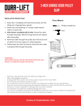
STE P I Assemble Tee Rail & Attach Cable Pulley Bracket
,.,,i ::::=
TEE RAIL BACK _'
(TO CHASSIS V
CAUTION: Do not tighten the lock nuts until bolt ./ /A
necks are seated in square holes°
TeeRail /////
(End Section___
"eL_ C.r.._ea0,
_,_ / ,_/7_ki_ !f 4".20xl/2''
Tee Rail
(Center Section
'_. Flange
1/4" Lock Nut
_/'_" Squar_ " g
Align front end of tee rail with cable pulley bracket and
connect as shown, Tighten screws and nuts securety_
PROCEDURE: Place the 3 Tee rail sections on a flat
surface for assembly. TH IS IS IMPORTANT. The center
section has two connection flanges., The end sections
are identical.
Refer toillustration. BE SURE CENTER SECTION IS
POSITIONED ON THE CORRECT SIDE OF TEE
RAIL. (When assembled, Tee rail has a front-to-back
position as shown).
Bolt center rail section to end sections with the hard-
ware illustrated_
SQUARE NECKS ON CARRIAGE BOLTS MUST BE
SEATED IN SQUARE HOLES IN TEE RAILS,
Cable Pulley
Bracket
Lock Washer
5f16"
Nut
r 5t16"

Assemb v
S=_E P 2 Connect Trolley & Attach Chain Retainer Bracket
Asa temporary stop, insert a screwdriver into Tee
rail as shown. Slide the inner trolley onto the Tee
rail, as shown, until it is firmly against the screw-
driver,Slide the outer trolley onto the Tee rail until it
partially engages the inner trolley and stops
TO FULLY ENGAGE TROLLEY: With a hammer,
firmly tap the back end of outer trolley just below the
rail guide. Outer trolley must move forward to fully
engage inner trolley., Be careful to avoid damaging
trolley spring,
Temporary Stop
Screwdriver
Cable
Pulley
Bracket
Outer
Nut
Lock Washer _,,,_5/17"
6"
5/16" _..
inNnu_r X ). ' ,Chain
Retainer
Bracket
Tl_readed
End
Fiat End
Trolley
Shaft
Attach inner nut, lock washer, chain retainer bracket
and outer nut to trolley shaft in the order shown The
retainer bracket should be kept in the illustrated
position DO NOT TIGHTEN NUTS UNTIL STEP 5,
PAGE 9
@
USE ON LY THOSE SCREWS MOUNTED
IN TOP OF OPENER CHASSlS. FAILURE
TO DO SO WILL CAUSE SERIOUS DAM-
AGE TO THE DOOR OPENER,
PROCEDURE: Place opener chassis on packing
material to protect cover,, For convenience, place a
support under the cable pulley bracket,
Remove 5/16"-18xt/2" washered screws mounted
in top of opener chassis, Align holes in back end of
Tee rail with holes in opener chassis, Fasten the rail
to the chassis with washered screws previously
rein eyed. CA UTION: USE ONL Y THESE SCREW St
Use of any other screws will cause serious dam-
age to door opener. Tighten screws securely
Insert a 5/t 6"-18xt/2" washered screw into the per _
manent stop hole in the Tee rail back section as
shown.. Tighten securely with a 5/16" nut.
Tee Rail
(Back Section)
Nut
5/16"-18

Assembly
ST_ P 4. Install Chain and Cable
Master
Link
DO NOT REMOVE CHAIN AND CABLE FROM DIS.
PENSER CA RTON.
Detach cable from side of carton and fasten to trolley
with a master link from coin envelope
CabIe
MASTER LINK PROCEDURE: Push pins of master
link bar through loop of cable and hole in fiat end of
trolley shaft Push cap onto pins and into notches
Slide clip-on spring over cap and into pin notches
until both pins are locked in place..
Pin
Notch Bar
Flat End
Troliey
Shaft
Opene{ Chassis
Sprocket
CAUTION: Keep chain taut while dispensing from
carton to help prevent kinking°
Slide trolley tight against screwdriver stop Dispense
cable around pulley bracket. Proceed back around
the opener sprocket and forward to chain retainer
bracket. Be sure teeth on chassis sprocket engage
chain.
Connect chain to chain retainer bracket, as shown in
inset, using second master link from coin envelope
NOTE: Check to make sure chain is not twisted.
Chain
Tee Rail
Chain
Retainer
Washered Screw Bracket
5/t 6"-t 8xl/2 °`
5/16"-t 8
Cable
Pultey
Bracket
Master
Link
Master
Link
Threaded End
of Trolley Shaft
_tley
As a permanent trolley stop, insert 5t16" washered
screw into remaining hole in Tee rail front, Tighten se-
curelywith 5/16" nut. REMOVE TEMPORARYSTOP
INSERTED IN STEP 2,

Ass÷mbUv
g_g P 5 Tighten the Chain and Cable
OAUTIONt Keep chain from twisting as nuts are
turned,
Loosen Tighten
Inner Outer
Nut Nut
O Lock
Washer
Chain
Retainer
Bracket
Trolley
Chain
1/2 Inch
i
Base of Tee Rail
PROCEDURE: Connect chain and cable to threaded
shaft of trolley in the order illustrated: inner nut, lock-
washer, chain retainer bracket and outer nut
Tighten the chain and cable by threading outer nut
toward trolley,
Chain is properly tightened when it is approximately
1/2" above the base of Tee rail midway between
cable pulley bracket and chassis.
When chain tension is correct, turn inner nut toward
chain retainer bracket until tight,
Sprocket noise can result if chain is either too
loose or too tight.
CAUTION: Do not overtighten chain and cable.
Refer to Page 21.
STEP (_ Attach Sprocket Cover to Opener Chassis
Sprocket
Cover
tl
PROCEDURE: Attach sprocket cover to chassis as
shown in Illustrations (A) and (B). insert back tab in
chassis slot Then bend cover forward and insert
front tab in slot provided on mounting plate,
Mounting
Plate
ASSEMBLY OF YOUR GARAGE DOOR OPENER IS NOW COMPLETE.
CERTAIN INSTALLATION PROCEDURES VARY ACCORDING TO GARAGE DOOR TYPES. WHERE DIFFER-
ENCES OCCUR, BE SURE TO FOLLOW ONLY THOSE INSTRUCTIONS WHICH APPLY TO YOUR DOOR
CONSTRUCTION,,
DO NOT WEAR WATCHES, RINGS OR LOOSE CLOTHING WHILE INSTALLING OR SERVICING A DOOR OPENER°
KEEP GARAGE DOOR BALANCED. STICKING OR BINDING DOORS MUST BE REPAIRED. GARAGE DOORS,
DOOR SPRINGS, CABLES, PULLEYS, BRACKETS AND THEIR HARDWARE MAY BE UNDER EXTREME TEN-
SION AND CAN CAUSE SERIOUS PERSONAL INJURY,, DO NOT ATTEMPT ADJUSTMENTS. CALL A GARAGE
DOOR SERVICEI_IAN TO MOVE, LOOSEN OR ADJUST DOOR SPRINGS OR HARDWARE,.
9

Instalaation
Completed installations of header bracket, door bracket with plate and door arm (depending on door type) are shown
below.. The header bracket supports the front end of the Tee rail. The door bracket connects door arm to troltey,
IT IS RECOMMENDED THATTH E OPENER BE INSTALLED 7 FEETOR MOREABOVE THE FLOOR WHERE SPACE
PERMITS. Follow only those instructions which apply to your door type as shown on Page 5.
STEP 1
Install Door Bracket and Plate
TO PREVENT DAMAGE TO LIGHTWEIGHTGARAGE DOORS, ALWAYSREINFORCE THE INSIDE OF DOOR--
BOTH VERTICALLY AND HORIZONTALLYMWITH 2x4 BOARDS OR ANGLE IRON.
Horizontal brace should be at least 6 feet tong Verticat brace should cover height of top panel. Reinforcement
hardware is not supplied (See No t Below.) FASTEN SECURELY AS SHOWN BEFORE INSTALLING DOOR
BRACKET AND PLATE_
Sectional Door installation Procedure
With door closed, locate and markthe vertical center-
line of garage door. Extend line onto header wail
above door.
Header
:kel
L
Header
Wall
I
Door Bracket &
P{ate Assy
SECTIONAL DOOR
Door
Arm
1. Assemble door bracket and plate as shown Cen-
ter bracket on vertical guideline (or up to one foot left
or right of center if necessary)
2o Position bracket assembly on face of door within
the following limits: A. Top edge of bracket 2" to 4"
below the top edge of door B. Directly below any
structural support across top of door.
Placement depends on your particular needs
3. Mark and drill 5/! 6"TOP and BOTTOM fastening
holes Secure bracket as shown
Vertical
Center--
Line
Carriage Bolt ._
5/16"-18x2-1/2"
TOp of Door
Board for Inside Edge
Lightweight Doors of Door or
Reinforcement Board
Door
Bracket
Door Bracket
Plate
Lock
Washer
5/16"
Nut
5/16"-18
All One-Piece Door installation Procedure
With door closed, locate and mark vertical centerline
of door,, Extend line onto header wall above door
NOTE: The door bracket has left and right side
fastening holes. Assemble door bracket and plate
if your installation requires top and bottom fas-
tening holes. (Refer to illustration).
Center bracket (with or without plate as required) on
top edge of door as shown Mark and dri]I two 5/16"
fastening holes and secure door bracket. NOTE: if
door has no exposed framing, drill 3/16" pilot
holes and substitute 5/16" x 1-1/2" lag screws
(not supplied) to fasten bracket to top of door°
Lock Washer
5/16"
Door,
5t16"-!8
Bracket
Plate
Top Edge
of Door
(Outside) - (Optiona!)
Carriage Boil
5/16"-t8x2-1/2'"
NOTE: Door bracket may be installed on face of
door if required for your installation. (Refer to
dotted line drawing). HOWEVER, drill 3/16"pilot
holes and substitute 5/16" x t-1/2" lag screws
(not supplied) to fasten bracket to door_
Face of DOOr
installation
Vertical
Center
Line
ONE PIECE DOOR
Door Brackel
Plate
(Optional)
lO

nstanUation
S=_E P 2 Position & Install Header Bracket
THE HEADER BRACKET MUST BE RIGIDLY FASTENED TO THE HEADER WALL OR CEILING., REINFORCE
WALL OR CEILING WITH 2x4 IF NECESSARY,,
Locate height for header bracket by opening door to
highest point of travel as shown. Draw a horizontal
line on header wall 2" above high point This height
provides travel clearance for top edge of door
When headroom is not sufficient for 2" clearance,
bottom edge of bracket may be placed parallel to the
hig!_ point of travel, or bracket may be attached to
ceiling
Optional Quick Turn Brackets are designed for low
headroom installations They replace top brackets
and roilers on the garage door, thereby lowering the
high point of door travel Installation instructions are
contained in the accessory carton
Position bracket as shown (bottom edge of bracket
on horizontal line) Mark either top and bottom or left
and right bracket holes Drilt 3/I6" pilot holes and
fasten bracket
Header
Bracket
J
,/
/
//_ ./
1 /" Lag Screws
F_ /i_ 5/16"-18x1"7/8'_
INSTALLATION
SECTIONAL DOOR AND
l-PIECE DOOR WITH TRACK
SECTIONAL DOOR
CURVED TRACK
Ceiling
Header
Bracket Track
Highest Point
of Travel
Door
ONE-PIECE DOOR
HORIZONTAL TRACK
JAMB HARDWARE
Header
Bracket
ack
INSTALLATION
1-PIECE DOOR WITHOUT TRACK
ONE-PIECE DOOR ONE+PIECE DOOR
NO TRACK NO TRACK
PIVOT HARDWARE -JAMB HARDWARE
Locate height for header bracket by opening door to
highest point of travel as shown, Measure distance
from top of door to floor. Subtract actual height of
door Add 8" to the remainder See example below,
If the total number of inches exceeds the height
available in your garage, use the maximum height
possible On finished ceilings, do not position the
bracket closer than 1/2" from ceiling,,
Measuring from top of door, draw a horizontal line on
the header wall at the determined height Position
bottom edge of header bracket on horizontal Hne,
centering bracket on vertical line. Mark either top
and bottom or left and right hole& Drill 3/16" pilot
holes and fasten with 5/16" x 1+7/8 '' lag screws as
shown above
EXAMPLE
Distance from top of door (at
highest point of travel) to floor 92"
Actual height of door -88"
Remainder 4"
Add + 8"
Bracket height on header wall =12"
1t

nstamlation
STEP 3 Attach Tee Rail to Header Bracket
Clevis Pin _- Cotter
5/t6"'x2-3/4- !1j Pin
He8
Bracket Cable
Pulley"
B_acket
PROCEDURE: Position opener chassis on garage
floor below door' and header brackets. Use packing
material base to protect cover NOTE: To enable
Tee rail to clear sectional door springs, it may be
necessary to lift the chassis onto a temporary
support.
CAUTION: Chassis must either be secured to sup-
port or held firmly in place by another person.
Raise Tee rail until cable pulley and header brackets
come together.. Align bracket holes and join with
clevis pin as shown Insert and spread cotter pin to
secure.
Packing Materiat
STE P 4 po,,io. Opener Chassis
TO PREVENT DAMAGE TO ALL LIGHTWEIGHT DOORS, AND DOORS WITH WINDOWS, DO NOT RESTTHE
OPENER ON THE DOOR..
SECTIONAL and ONE-PIECE
DOOR WiTH TRACK
nNSTA LL&_ II0 N
NOTE: A 2x4 is convenient for setting an ideal
door-to-Tee rail distance, it is not necessary
where headroom is insufficient°
PROCEDURE: Raise the opener chassis onto a
stepladder. Open the garage door Place a 2x4 on
edge on top section of door directly above door
bracket. Rest Tee rail on 2x4
Tee Rail
2x4
Door
Ste
ONE-PRECE DOOR
WITH NO- TRACK
INSTALLATnON
PROCEDURE: Measure the distance from floor to
top of door (in fully open position and paratlei to
floor)
Using a stepladder as a support, raise the opener
chassis to the same distance from the floor (chassis
witt have a slight angle as shown)
The top of the door should be level with the top of the
opener For maximum efficiency, do not position the
opener chassis more than 2 inches above this poinL
Header
Top o! Opener
I
Door I
Bracket I
i
I
I
Equat I
--_ Distance --4
from I
Floor I
I
I
t
12

UnstaIlation
STEP 5 Hang Opener Chassis
THE OPENER CHASSIS MUST BE ATTACHED TO A
STRUCTURAL SUPPORT OF THE GARAGE Three
representative installations are shown_Yours may be
different, Hanging brackets should be angled to pro-
vide rigid support,
PROCEDURE: On EACH side of opener measure
the distance from chassis to structural support,,
Cut both pieces of the hanging bracket to required
lengths. Flatten one end of each bracket and bend or
twist to fit fastening angles_ DO NOT BEND AT BRAC-
KET HOLES Drill 3/16" pilot holes in structural sup-
port. Fasten flattened ends of brackets to support
as shown,,
Lift opener and fasten to hanging bracket as shown,,
Checkto make su re Tee rail is centered over door
bracket. Close the garage door. If door hits rail,
raise header bracket. REMOVE 2x4o
Grease rail surfaces on which trolley slides_ Atube of
grease is supplied,,
Lag Screws
5/16"xt-7/8"'
Bracket Finished
(Not Supplied) Ceiling
Screws
5/16"xl-7t8"
_TE P _ Attach Emergency Release Rope & Handle
USE EMERGENCY RELEASE ONLY TO DIS-
ENGAGE TROLLEY. DO NOT USE RED Overhand
EMERGENCY RELEASE ROPE AND HAN_ Knot
DLE TO PULL DOOR OPEN OR CLOSED_
PROCEDURE: Thread one end of rope through hole
in top of red handle so 'NOTICE' reads right side u15
as shown_ Secure with an overhand knot NOTE: Knot
should be at least I inch from end of rope to pre-
vent slipping, Thread other end of rope through
hole in release arm of outer trolley, Adjust rope length
so that handle is 6 feet above the floor,, Secure with
an overhand knot as above,,
NOTE: If it is necessaryto cut rope, heat seal cut
end with a match or lighter to prevent fraying
and/or raveling,
Rope_
Trolley
Release Arm
_- overhand
Knot
13

Top
_nsta_lation
Flange
r
Bo|tom
Installation
Flange
i
Wall
Control
Terminals
INSTALL "WALL CONTROL (OR ADDITIONAL
PUSH BUTTONS) OUTOFTHE REACH OFCHIL-
DREN,_ DO NOT ALLOW CHILDREN TO OPER-
ATE WALL CONTROL OR TRANSMITTER_
SERIOUS PERSONAL INJURY FROM A CLOS-
ING GARAGE DOOR MAY RESULT FROM ANY
MISUSE OF OPENER°
FASTEN THE CAUTION LABEL ON THE WALL
NEAR THE WALL CONTROL AS A REMINDER
OF SAFE OPERATING PROCEDURES,.
PROCEDURE: There are 4 screw terminals on the
back of the Wall Control Connect the bell wire by
color; yellow to yellow, white to white, red to red and
black to black,
Fasten Wail Control to an inside garage wall, as shown,
with the 8ABxl "sheet metal screws provided. A con-
venient place is beside the service door and OUT OF
THE REACH OF CHILDREN
Right Side
Panel
of
Opener
o O
O
C:3
Antenna
Opener
Terminats
Run the belt wire up the wall and across the ceiling to
the garage door opener_ Use insulated staples
The receiver terminals as well as the antenna are
located on the right side panel of the opener., Bend
antenna wire down until it isparallel to chassis panef
Then connect the wire by color to the red, white,
black and yeltow opener terminal screws..
WIRING INSTRUCTIONS FOR ACCESSORIES
Infrared Reversing System:
To white & black opener terminals
Open Door Indicator:
To white & orange opener terminals
Key Switch:
To red & white opener terminals
Vacation
Push Button
Wall Control
Push Button
Work Light
Push Button
OPERATION OF WALL CONTROL
WALL CONTROL PUSH BUTTON
Press and release to open or clQse door
Press and release again to REVERSE door during CLOSING cycle
or to STOP door during OPENING cycle
VACATION PUSH BUTTON
Activate Vacation feature only when door is In closed position,
Press and release, Push button light will turn ON The Vacation fea-
ture was designed to prevent operation of door from the transmitter
and aEiow door to travel in the UP direction ONLY from the Wall Con _
trol push button (press and release) and Key Switch accessory
Press and release again. Push button light witl turn OFE Opener will
return to normal operation
A power failure of more than 30 seconds will cause the vacation
feature to turn OFF,
WORK LIGHT PUSH BUTTON
Press and release Opener tight will turn on and remain on
Press and release again Opener light wilt return to normal operation.
14

0nstatUation
STEP 8 ConnectElectricPower
I
TO AVOID SERIOUS PERSONAL INJURY FROM ENTANGLEMENT, REMOVE ALL ROPES CON NECTEDTO THE I
GARAGE DOOR BEFORE OPERATING DOOR OPENER_
REMOVE EXISTING GARAGE DOOR LOCKS OR USE A WOOD SCREW OR NAIL TO MAKE THE_,_INOPERATIVE,
INSTALLATION AND WIRING MUST BE IN COMPLIANCE WITH LOCAL BUILDING AND ELECTRICAL CODES.
OPERATION AT OTHER THAN !2OV 6OHz WILL CAUSE OPENER MALFUNCTION AND DAMAGE,
IF LOCAL ELECTRICAL CODES DO NOT REQUI RE
PER MAN ENT WIRING: Insert the 3-prong plug into a
3-hole receptacle. UNIT MUST BE GROUNDED DO
NOT USE A 2-WIRE ADAPTER,
IF LOCAL CODES REQUIRE PERMANENTWIRING:
Refer to illustration,
PROCEDURE: Make connection through 7/8 inch
diameter hole in top of opener chassis,
1o Remove opener chassis cover by removing the 4
cover screws,
2,, Remove attached 3-prong cord,
3. Connect black (line) wire to black wire on terminal
block; white (neutral) wire to white terminal wire; green
(ground) wire to green ground screw
CAUTION: BE SURE UNIT IS GROUNDED
ACCORDING TO LOCAL CODE
Ground Tab
Ground Screw
I Wire
_,White
Wire
STEP 9 i. to, Lights andLenses
PROCEDURE: Install a 75 watt maximum light bulb
in each socket as shown The lights turn on automatF
calty when opener starts. After 4-I/2 minutes they
will turn off, Lights will REMAIN ON when Work Light
push button on Wail Control is pressed,
IMPORTANT NOTE: If the lights in your garage
door opener do not work, it may NOT be the fault of
the opener° Some short-neck butbs_ because of
their shape, do not make contact with the socket
base tab. Use standard.neck bulbs°
INSTALLING LENSES: Slide lenses into the fens
guides as shown. Snap bottom tabs into lens slots.
(The force and limit adjustment settings are located
on side panels behind lenses),
NOTE: FOR CONVENIENCE, LENSES MAY BE IN-
STALLED AFTER ADJUSTMENT, STEP 3, PAGE 20_
Lens Tab
Lens
Slot
Lens
Guide
15

instal|ation
: _ ,rrr_....... ................... ,hr
ST_ P "I 0 Connect Door Arm to Trolley
: ..........:r,,,, ................. .............
SECTIONAL DOOR INSTALLATION ONLY
PROCEDURE: Fasten straight door arm section to
trolley and wedge door arm section to door bracket,
as shown (A)Insert and spread a cotter pin to secure
each connection_
B
A !'_ _ .___
,/II ,ov,s ,n
Do,,, /1 I_1--- Straight
Lock
Nut Washers
5/!6"q8 5/16"
Door
Bracket
Bring the door arm sections together. Find a pair of
holes that line up and join sections as shown (B),
INSTALLATION FOR SECTIONAL DOOR IS COMPLETE. PROCEED TO ADJUSTMENT STEP 1 , PAGE 18.
ALL ONE-PIECE DOOR iNSTALLATiONS
ASSEMBLE DOOR ARM PROCEDURE: Fasten
straight and wedge door arm sections together to
their longest possible length.With door.closed,con_
nect straight door arm section to door bracket as
shown, insert and spread cotter pin to secure.
Cotter Pin --I Door
Clevis Pin
Straight
Door Arm
Wed_
Door
Screws
5/16"-18 x 7/8"
Lock Washer
5/16"
16

nstam ation
STE P 11 Adj.,,Limits(All One-PieceDoorsOnly)
CAUTION: To prevent damage to garage doors,
the opener limits must be adjusted on ALL ONE-
PIECE DOORS,
Limit Adjustment settings regulate the points at
which door will stop when moving up or down.
Repeated operation of the opener during adjustment
may cause the motor to overheat and shut off. Simply
wait 15 minutes and continue adjustments,
Limit adjustment screws are located on the left side
panel of the openeras shown Increase limits by turn-
ing screws in direction shown on label.. Decrease
limits by turning screws in opposite direction._
Left Side
Panel Limit
Adjustment
Screws
Adjustment Label
The following illustration shows the position of the door arm and trolfeywhen the door is open (solid line drawing),
and when the door is closed (dotted line drawing),
Fully Closed
Trolley
!
1
L Closed
I Door
i
t
Door Door
Arm
Arm
Bracket
C
ADJUSTMENT PROCEDURES
PROCEDURE - OPEN DOOR ADJUSTMENT
DECREASE the U P limit by turning the UP Hmit adjust _
ment screw counterclockwise 8 complete turns
Press Wall Control push button., Trolley will travel ta
full open position..
Manually raise garage door to open position (paraF
lel to floor) and lift door arm to trolley, The arm should
touch trolley just in back of door arm connector hole
as shown in solid line drawing if the arm does not
extend far enough, make further DECREASED limit
adjustment,, One full turn equals 2 inches of door
travel,
PROCEDURE - CLOSED DOOR ADJUSTMENT
DECREASE the DOWN limit by turning the DOWN
limit adjustment screw clockwise 4 complete turns
Press Wall Control push button. Trolley will travel to
full closed position,
Manually close garage door and lift door arm to the
trottey, Arm should touch trolley just ahead of door
arm connector hole as shown in dotted line drawing,,
If arm is behind the connector hole, make further
DECREASED limit adjustment, One full turn equals 2
inches of door travel.
CONNECT DOOR ARM TO TROLLEY PROCEDURE: With door closed,join wedge door arm to connector hole in
trolley with the remaining clevis pin, Secure with acotter pin. NOTE: It may be necessary to lift door slightly to
make connection.
Run the opener through a complete travel cycle ifdoor has a slight 'downward' slant infull open position, turn the
UP limit adjustment screw counterclockwise to decrease travel until door is paraiiel to floor
17

Adjustment
STEP 1
,, ,, ,, _ ,,....... ,,,, ...... ,,,,,,,,,,
Adjust UP and DOWN Limits
The limit adjustment screws are located on the left side panel of the opener chassis as shown LI MITADJUSTMENT
settings regulate the points at which the door will stop when moving up or down
NOTE: Door STOPS in UP direction if anything interferes with door travel_ Door' REVERSES in DOWN direc-
tion if anything interferes with door travel (including binding or unbalanced doors).
PROCEDURE: To operate opener, press Wall Con_
trot Push Button or transmitter push button. Run the
opener through a COMPLETE TRAVEL CYCLE No
adjustments are needed when the door- opens and
closes completely and does not reverse uninten-
tionally in down direction.
The following chart outlines adjustment procedures.
Run opener through a COMPLETE TRAVEL CYCLE
AFTER EACH ADJUSTMENT. NOTE: REPEATED
OPERATION OFTH E OPEN ER DURING ADJUST-
MENT PROCEDURES MAY CAUSE THE MOTOR
TO OVERHEATAND SHUTOFFo SIMPLY WAtT 15
MINUTES AND TRY AGAIN° Read the chart care-
fully before proceeding to Step 2, Pg 19 Use a screw-
driver to make limit adjustments
iloo
Limit
Adjustment
Screws
Adjustment Label
LIMIT ADJUSTMENT CHART
IF DOOR DOES NOT
OPEN COMPLETELY
BUT OPENS AT
LEAST FIVE FEET
IF DOOR DOES NOT
CLOSE COMPLETELY
IF DOOR REVERSES
WHEN CLOSING AND
THERE IS NO INTER-
FERENCE TO
TRAVEL CYCLE
Increase UP travel by turning UP LIMIT adjustment screw in
clockwise direction as shown on label One turn equals 2
inches of travel
if door doesn't open at least 5 feet, adjust OPEN FORCE as
explained in Step 2, Page 19
1o ON SECTIONAL DOORS:
Lengthen the door arm (See Step 10, Page 16),
If door arm is at maximum length, increase the DOWN travel
by turning the down limit adjustment screw in a counter
clockwise direction as shown on label, One turn equals 2
inches of travel,
If door still will not close completely, the header bracket is
positioned too high, Repeat Step 2, Page 1t
2o ON ONE-PIECE DOORS:
Increase DOWN travel by turning tile down limit adjustment
screw in acounterclockwise direction as shown on label, One
turn equals 2 inches of travel.,
TEST DOOR FOR BINDING
Pull emergency release handle and manually open and close
the door, tf door is binding, call a door serviceman
1. IF OPENER REVERSES BEFORE DOOR CLOSES FULLY:
Adjust the CLOSE FORCE as explained in Step 2, Page 19
2,, 1FOPENER REVERSES IN FULLY CLOSED POSITION:
Decrease DOWN travel Turn the down limit adjustment screw
in clockwise direction. One turn equals 2 inches of travel
18

STEP 2 Adjust
DO NOT USE FORCE ADJUSTMENTS TO COMPENSATE FOR A BINDING OR STICKING GARAGE DOOR,
EXCESSIVE FORCE WILLINTERFERE WITH THE PROPER OPERATION OFTHE SAFETY REVERSE SYSTEM
OR DAMAGE THE GARAGE DOOR.
Force Adjustment Controls are located on right side
panel of the opener chassis,, FORCE ADJUSTMENT
settings regulate the amount of power required to
open and close the door
NOTE: Door STOPS in UP direction if anything
interferes with door travel° Door REVERSES in
DOWN direction if anything interferes with door
travel (including binding or unbalanced doors)°
If force adjustments are set too light, door travel may
be interrupted by nuisance reversals in the DOWN
direction and stops in the UP direction As weather
conditions can affect door movement, occasional
adjustment may be needed
The maximum force adjustment range is 260 degrees,
about 3/4 of a complete turn, Do not force controls
beyond that point Turn force adjustment controls
with a screwdriver,
Controls
Adjustmenl
Label
FORCE ADJUSTMENT CHART
IF DOOR DOESN'T
OPEN AT LEAST 5 FT:
IF DOOR REVERSES
DURING THE DOWN
(CLOSE) CYCLE:
TEST DOWN
(CLOSE) FORCE:
Increase UP (OPEN) FORCE by turning control in a clock-
wise direction as shown on label Make 10 degree turn adjust-
ments until door opens completely, Readjust UP LIMIT if
necessary. After each adjustment, run the opener through a
complete travel cycle
increase DOWN (CLOSE) FORCE by turning control in a
clockwise direction as shown on label, Make 10 degree turn
adjustments until door completes the close cycle, After each
adjustment, run opener through a complete travel cycle_
Grasp the door handle or door bottom when door is about
halfway tiirough DOWN (CLOSE) TRAVEL,. The door should
reverse If the door is hard to hold or doesn't reverse, de-
crease the DOWN (CLOSE) FORCE by turning the control in a
counter clockwise direction Make 10 degree turn adjust-
ments until the door reverses normally, After each adjust-
ment, run the opener through a complete travel cycle,
19

THE SAFETY REVERSE SYSTEM TEST iS IMPORTANT. THE GARAGE DOOR MUSTREVERSE ON CONTACT
WITH A ON E 1NC H OBSTAC LE PLACED ON TH E FLOOR. FAILU RE TO PROPE R LY ADJ UST TH E OPE N E R MAY
RESULT IN SERIOUS PERSONAL INJURY FROM A CLOSING GARAGE DOOR° REPEAT THE TEST AT LEAST
ONCE A YEAR AND MAKE ANY NEEDED ADJUSTMENTS,
PROCEDURE: Place a 1-inch obstacle on the floor under the garage door Operate the door in the DOWN
direction,. The door must reverse on the obstruction
if a SECTIONAL door STOPS on the obstruction,
lenghthen door arm (Step 10, Page 16) until the door
reverses in DOWN direction._
If a ONE-PIECE door- stops on obstruction, door is
not traveling far enough in DOWN direction Increase
the DOWN limit by turning the DOWN limit adjust-
mentscrewcounter-clockwise 1/4 turn REPEATTEST,,
When the door reverses on the 1-inch obstruction,
remove obstruction and run opener through a com-
plete travel cycle, Door must not reverse in closed
position, if it does, repeat Adjustment Steps 2 and 3
ONE-PIECE DOOR
ch ObstruCtion
SECTIONAL DOOR
I
/
f
REPEAT ADJUSTMENT STEP 3 AFTER:
1. EACH ADJUSTMENT OF DOOR ARNI LENGTH, CLOSE FORCE OR DOWN LIM|T
2. ANY REPAIR OR ADJUSTMENT OFTHE GARAGE DOOR (INCLUDING SPRINGS AND HARDWARE}
3. ANY REPAIR OR BUCKLING OF THE GARAGE FLOOR
4, ANY REPAIR OR ADJUSTMENT OF THE GARAGE DOOR OPENER
(Optional) STEP 4" install tnfrared Reversing System
The INFRARED REVERSING SENSOR provides an
ADDITIONAL measure of safety against small child-
ren being caught under a garage door, tt uses an invis _
ibte beam which, when broken by an obstruction,
causes a closing door to open or prevents an open
door from closing
After the garage door opener has beeh completely
installed and adjusted, the INFRARED REVERSING
SENSOR accessory car] be installed, Instructions are
included with this optional device
CAUTION: The Infrared Reversing Sensor will not
be in effect when Vacation Light is ON,
2O
/