Lennox 14ACX User manual

Category
Split-system air conditioners
Type
User manual
07/11 506645−01
*2P0711* *P506645-01*
Page 1
2011 Lennox Industries Inc.
Dallas, Texas, USA
RETAIN THESE INSTRUCTIONS
FOR FUTURE REFERENCE
These instructions are intended as a general guide and do
not supersede local codes in any way. Consult authorities
who have jurisdiction before installation.
WARNING
Improper installation, adjustment, alteration, service or
maintenance can cause personal injury, loss of life, or
damage to property.
Installation and service must be performed by a licensed
professional installer (or equivalent) or a service agency.
IMPORTANT
The Clean Air Act of 1990 bans the intentional venting of
refrigerant (CFCs, HCFCs and HFCs) as of July 1, 1992.
Approved methods of recovery, recycling or reclaiming
must be followed. Fines and/or incarceration may be
levied for noncompliance.
IMPORTANT
This unit must be matched with an indoor coil as
specified in Lennox Engineering Handbook. Coils
previously charged with HCFC−22 must be flushed.
NOTICE TO INSTALLER
UNIT PLACEMENT
It is critical for proper unit operation to place outdoor unit on an
elevated surface as described in Unit Placement section on page 7.
BRAZING LINE SET TO SERVICE VALVES
It is imperative to follow the brazing technique illustrated starting on
page 11 to avoid damaging the service valve’s internal seals.
INSTALLATION
INSTRUCTIONS
Merit
®
Series 14ACX Units
CONDENSING UNITS
506645−01
07/11
Supersedes 11/10
TABLE OF CONTENTS
Shipping and Packing List 1. . . . . . . . . . . . . . . . . . . . . . . .
General 1. . . . . . . . . . . . . . . . . . . . . . . . . . . . . . . . . . . . . . . .
Unit Dimensions 2. . . . . . . . . . . . . . . . . . . . . . . . . . . . . . . . .
Typical Unit Parts Arrangement 3. . . . . . . . . . . . . . . . . . .
Model Number Identification 3. . . . . . . . . . . . . . . . . . . . . .
Operating Manifold Gauge Set and Service Valves 4. . .
Recovering Refrigerant from Existing System 6. . . . . . .
New Unit Placement 7. . . . . . . . . . . . . . . . . . . . . . . . . . . . .
Removing and Installing Louvers 8. . . . . . . . . . . . . . . . . .
New or Replacement Line Set 9. . . . . . . . . . . . . . . . . . . . .
Brazing Connections 11. . . . . . . . . . . . . . . . . . . . . . . . . . .
Flushing Line Set and Indoor Coil 14. . . . . . . . . . . . . . . .
Installing Indoor Metering Device 15. . . . . . . . . . . . . . . .
Leak Test Line Set and Indoor Coil 16. . . . . . . . . . . . . . .
Evacuating Line Set and Indoor Coil 17. . . . . . . . . . . . .
Electrical Connections 18. . . . . . . . . . . . . . . . . . . . . . . . . .
Servicing Unit Delivered Void of Charge 22. . . . . . . . . . .
Unit Start−Up 22. . . . . . . . . . . . . . . . . . . . . . . . . . . . . . . . . . .
System Refrigerant 22. . . . . . . . . . . . . . . . . . . . . . . . . . . . .
System Operation 28. . . . . . . . . . . . . . . . . . . . . . . . . . . . . .
Maintenance 28. . . . . . . . . . . . . . . . . . . . . . . . . . . . . . . . . . .
Start−Up and Performance Checklist 30. . . . . . . . . . . . . .
Shipping and Packing List
Check the unit for shipping damage and listed times below
are intact. If damaged, or if parts are missing, immediately
contact the last shipping carrier.
1  Assembled outdoor unit
1  Refrigerant flow control kit (fixed orifice)
1  Liquid line filter drier
General
14ACX Air Conditioners, which will also be referred to in
this instruction as the outdoor unit, uses HFC−410A
refrigerant. This outdoor unit must be installed with a
matching indoor unit and line set as outlined in the Lennox
14ACX Engineering Handbook.
This outdoor unit is designed for use in systems that use
one of the following refrigerant metering devices:
Thermal expansion valve (TXV)
Fixed orifice
Litho U.S.A.
Page 2
506645−01
Unit Dimensions − Inches (mm)
SUCTION AND LIQUID
LINE CONNECTION
DISCHARGE AIR
SIDE VIEW
OUTDOOR
COIL FAN
COMPRESSOR
A
B
A
OPTIONAL UNIT STANDOFF KIT (4)
(FIELD INSTALLED)
SIDE VIEW
Model Numbers A B
14ACX−018−230 24−1/4 (616) 29−1/4 (743)
14ACX−024−230 28−1/4 (724) 33−1/4 (845)
14ACX−030−230 28−1/4 (724) 37−1/4 (946)
14ACX−036−230 28−1/4 (724) 37−1/4 (946)
14ACX−042−230 28−1/4 (724) 29−1/4 (743)
14ACX−041−230 and 14ACX−048−230 28−1/4 (724) 37−1/4 (946)
14ACX−059−230 32−1/4 (819) 37−1/4 (946)
14ACX−047−230 and 14ACX−060−230 32−1/4 (819) 33−1/4 (845)
Page 3
14ACX SERIES
Typical Unit Parts Arrangement
COMPRESSOR
HARNESS
CONNECTION
LIQUID LINE SERVICE VALVE
SUCTION LINE SERVICE VALVE
OUTDOOR COIL
DISCHARGE LINE
HIGH PRESSURE SWITCH (S4)
COMPRESS0R (B1)
GROUND LUG
CONTACTOR
(K1)
CONTROL
DUAL RUN
CAPACITOR
(C12)
CONTROL WIRE
LOOP
CUTOUT FOR HIGH
VOLTAGE CONDUIT
NOTE  Plumbing layout and compressor type may vary between model sizes.
CRANKCASE HEATER
THERMOSTAT (S40)
SEE
NOTE
CRANKCASE HEATER
(HR1)
SEE
NOTE
NOTE − −041, −047, −048, −059 and −060 only are equipped with crankcase thermostat (S40) and
crankcase heater (HR1).
THERMAL SWITCH
(S173) (−036 AND
−060 ONLY)
Figure 1. Typical Unit Parts Arrangement
Model Number Identification
AC X14 024
Unit Type
AC = Air Conditioner
Refrigerant
X = R−410A
Cooling Capacity − Tons
018 = 1.5
024 = 2
030 = 2.5
036 = 3
041 = 3.5
042 = 3.5
047 = 4
048 = 4
059 = 5
060 = 5
Minor Revision Number
Nominal SEER
13
Voltage
230 = 208/230V−1phase−60hz
230
Page 4
506645−01
CAUTION
Physical contact with metal edges and corners while
applying excessive force or rapid motion can result in
personal injury. Be aware of, and use caution when
working near these areas during installation or while
servicing this equipment.
Operating Manifold Gauge Set and
Service Valves
These instructions are intended as a general guide and do
not supersede local codes in any way. Consult authorities
who have jurisdiction before installation.
TORQUE REQUIREMENTS
When servicing or repairing heating, ventilating, and air
conditioning components, ensure the fasteners are
appropriately tightened. Table 1 lists torque values for
fasteners.
IMPORTANT
Only use Allen wrenches of sufficient hardness (50Rc −
Rockwell Harness Scale minimum). Fully insert the
wrench into the valve stem recess.
Service valve stems are factory−torqued (from 9 ft−lbs for
small valves, to 25 ft−lbs for large valves) to prevent
refrigerant loss during shipping and handling. Using an
Allen wrench rated at less than 50Rc risks rounding or
breaking off the wrench, or stripping the valve stem
recess.
See the Lennox Service and Application Notes #C−08−1
for further details and information.
IMPORTANT
To prevent stripping of the various caps used, the
appropriately sized wrench should be used and fitted
snugly over the cap before tightening.
When servicing or repairing HVAC components, ensure
the fasteners are appropriately tightened. Table 1 provides
torque values for fasteners.
Table 1. Torque Requirements
Parts Recommended Torque
Service valve cap 8 ft.− lb. 11 NM
Sheet metal screws 16 in.− lb. 2 NM
Machine screws #10 28 in.− lb. 3 NM
Compressor bolts 90 in.− lb. 10 NM
Gauge port seal cap 8 ft.− lb. 11 NM
USING MANIFOLD GAUGE SET
When checking the system charge, only use a manifold
gauge set that features low loss anti−blow back fittings.
Manifold gauge set used with HFC−410A refrigerant
systems must be capable of handling the higher system
operating pressures. The gauges should be rated for use
with pressures of 0 − 800 psig on the high side and a low
side of 30" vacuum to 250 psig with dampened speed to
500 psi. Gauge hoses must be rated for use at up to 800
psig of pressure with a 4000 psig burst rating.
OPERATING SERVICE VALVES
The liquid and vapor line service valves are used for
removing refrigerant, flushing, leak testing, evacuating,
checking charge and charging.
Each valve is equipped with a service port which has a
factory−installed valve stem. Figure 2 provides information
on how to access and operating both angle and ball service
valves.
Page 5
14ACX SERIES
(VALVE STEM SHOWN
CLOSED) INSERT HEX
WRENCH HERE
SERVICE PORT CORE
SERVICE PORT CAP
ANGLE−TYPE SERVICE VALVE
(FRONT−SEATED CLOSED)
SERVICE PORT
CORE
TO OUTDOOR UNIT
STEM CAP
(VALVE STEM SHOWN OPEN)
INSERT HEX WRENCH HERE
TO INDOOR
UNIT
ANGLE−TYPE SERVICE VALVE
(BACK−SEATED OPENED)
BALL (SHOWN
CLOSED)
SERVICE PORT
CORE
TO INDOOR UNIT
TO OUTDOOR
UNIT
TO OPEN ROTATE STEM
COUNTERCLOCKWISE 90°.
TO CLOSE ROTATE STEM
CLOCKWISE 90°.
SERVICE PORT
SERVICE PORT
CAP
STEM CAP
VALVE
STEM
Operating Angle Type Service Valve:
1. Remove stem cap with an appropriately sized wrench.
2. Use a service wrench with a hex−head extension (3/16" for liquid line valve sizes and 5/16" for vapor line valve sizes) to back
the stem out counterclockwise as far as it will go.
Operating Ball Type Service Valve:
1. Remove stem cap with an appropriately sized wrench.
2. Use an appropriately sized wrenched to open. To open valve,
rotate stem counterclockwise 90°. To close rotate stem
clockwise 90°.
1
2
3
4
5
6
7
8
9
10
11
12
1/12 TURN
To Access Service Port:
A service port cap protects the service port core from contamination and
serves as the primary leak seal.
1. Remove service port cap with an appropriately sized wrench.
2. Connect gauge set to service port.
3. When testing is completed, replace service port cap and tighten as
follows:
With torque wrench: Finger tighten and
torque cap per table 1.
Without torque wrench: Finger tighten and
use an appropriately sized wrench to turn
an additional 1/6 turn clockwise.
1
2
3
4
5
6
7
8
9
10
11
12
1/6 TURN
WHEN SERVICE VALVE IS CLOSED, THE SERVICE PORT IS OPEN
TO
THE LINE SET AND INDOOR UNIT.
When service valve is OPEN, the service port is
open to linE set, indoor and outdoor unit.
Reinstall Stem Cap:
Stem cap protects the valve stem from damage and serves as the
primary seal. Replace the stem cap and tighten as follows:
With Torque Wrench: Finger tighten and
then torque cap per table 1.
Without Torque Wrench: Finger tight-
en and use an appropriately sized
wrench to turn an additional 1/12 turn
clockwise.
NOTE  A label with specific torque requirements may be affixed to the stem cap. If the label is present, use the specified torque.
Figure 2. Angle and Ball Service Valves
Page 6
506645−01
Recovering Refrigerant from Existing System
Use the following procedure to recover refrigerant from an existing system (indoor coil, line set and outdoor unit).
SERVICE
DISCONNECT
SWITCH
MAIN FUSE BOX/BREAKER PANEL
Disconnect all power to the existing outdoor unit at the service
disconnect switch or main fuse box/breaker panel.
DISCONNECT POWER
CONNECT MANIFOLD GAUGE SET
MANIFOLD GAUGES
RECOVERY MACHINE
CLEAN RECOVERY
CYLINDER
OUTDOOR UNIT
HIGH
LOW
Connect a gauge set, clean recovery cylinder and a recovery
machine to the service ports of the existing unit. Use the
instructions provided with the recovery machine to make the
connections.
METHOD 1:
Us this method if the existing outdoor unit is not equipped with shut−off valves, or if the unit is not operational and you plan to use the existing
HCFC−22 to flush the system.
Remove all HCFC−22 refrigerant from the existing system. Check gauges after shutdown to confirm that the entire system is completely void of
refrigerant.
METHOD 2:
Use this method if the existing outdoor unit is equipped with manual shut−off valves, and you plan to use new HCFC−22 refrigerant to flush the
system.
The following devices could prevent full system charge recovery into the outdoor unit:
Outdoor unit’s high or low−pressure switches (if applicable) when tripped can cycle the compressor OFF.
Compressor can stop pumping due to tripped internal pressure relief valve.
Compressor has internal vacuum protection that is designed to unload the scrolls (compressor stops pumping) when the pressure ratio meets
a certain value or when the suction pressure is as high as 20 psig. (Compressor suction pressures should never be allowed to go into a vacuum.
Prolonged operation at low suction pressures will result in overheating of the scrolls and permanent damage to the scroll tips, drive bearings and
internal seals.)
Once the compressor can not pump down to a lower pressure due to one of the above system conditions, shut off the vapor valve. Turn OFF the
main power to unit and use a recovery machine to recover any refrigerant left in the indoor coil and line set.
Perform the following task:
A Start the existing HCFC−22 system in the cooling mode and close the liquid line valve.
B Use the compressor to pump as much of the existing HCFC−22 refrigerant into the outdoor unit until the outdoor system is full. Turn the outdoor unit
main power OFF and use a recovery machine to remove the remaining refrigerant from the system.
NOTE  It may be necessary to bypass the low pressure switches (if equipped) to ensure complete refrigerant evacuation.
C When the low side system pressures reach 0 psig, close the vapor line valve.
D Check gauges after shutdown to confirm that the valves are not allowing refrigerant to flow back into the low side of the system.
Remove existing HCFC−22 refrigerant using one of the following procedures:
RECOVERING REFRIGERANT
IMPORTANT  Some system configurations may contain higher than normal refrigerant charge due to either large internal coil volumes,
and/or long line sets.
12
3
Figure 3. Refrigerant Recovery Procedure
Page 7
14ACX SERIES
6 (152)
36 (914)
12 (305)
30 (762)
LINE SET
CONNECTIONS
24 (610)
LINE SET
CONNECTIONS
ACCESS PANEL
48 (1219)
MINIMUM CLEARANCE BETWEEN
TWO UNITS
CLEARANCE ON ALL SIDES  INCHES (MILLIMETERS)
ACCESS PANEL
MINIMUM CLEARANCE
ABOVE UNIT
NOTES:
Clearance to one of the other three
sides must be 36 inches (914mm).
Clearance to one of the remaining
two sides may be 12 inches
(305mm) and the final side may be
6 inches (152mm).
Figure 4. Installation Clearances
Install unit level or, if on a slope, maintain slope tolerance of 2 degrees
(or 2 inches per 5 feet [50 mm per 1.5 m]) away from building structure.
DETAIL A
DETAIL B
INSTALL UNIT AWAY
FROM WINDOWS
TWO 90 ELBOWS INSTALLED IN LINE SET
WILL REDUCE LINE SET VIBRATION
GROUND LEVEL
MOUNTING
SLAB
BUILDING
STRUCTURE
DISCHARGE AIR
Figure 5. Placement, and Slab Mounting
New Unit Placement
See Unit Dimensions on page 2 for sizing mounting slab,
platforms or supports. Refer to figure 4 for mandatory
installation clearance requirements.
POSITIONING CONSIDERATIONS
CAUTION
In order to avoid injury, take proper precaution when
lifting heavy objects.
Consider the following when positioning the unit:
Some localities are adopting sound ordinances based
on the unit’s sound level registered from the adjacent
property, not from the installation property. Install the
unit as far as possible from the property line.
When possible, do not install the unit directly outside
a window. Glass has a very high level of sound
transmission. For proper placement of unit in relation
to a window see the provided illustration in figure 5,
detail A.
Page 8
506645−01
PLACING UNIT ON SLAB
When installing unit at grade level, the top of the slab
should be high enough above grade so that water from
higher ground will not collect around the unit. The slab
should have a slope tolerance as described in figure 5,
detail B.
ROOF MOUNTING
Install the unit at a minimum of 4 inches (102 mm) above
the surface of the roof. Ensure the weight of the unit is
properly distributed over roof joists and rafters. Redwood
or steel supports are recommended.
NOTICE
Roof Damage!
This system contains both refrigerant and oil. Some
rubber roofing material may absorb oil and cause the
rubber to swell when it comes into contact with oil. The
rubber will then bubble and could cause leaks. Protect
the roof surface to avoid exposure to refrigerant and oil
during service and installation. Failure to follow this
notice could result in damage to roof surface.
Removing and Installing Louvers
WARNING
To prevent personal injury, or damage to panels, unit or structure, be sure to observe the following:
While installing or servicing this unit, carefully stow all removed panels out of the way, so that the panels will not cause injury to personnel,
nor cause damage to objects or structures nearby, nor will the panels be subjected to damage (e.g., being bent or scratched).
While handling or stowing the panels, consider any weather conditions, especially windy conditions, that may cause panels to be blown
around and battered.
WARNING
PANEL A
PANEL B
PANEL C
PANEL D
When removing the unit panels. Remove panel A first, then B, C and
finally D. When reinstalling panels, reverse that order starting with panel
D, C, B and finally A.
REMOVAL
REPEAT STEPS 1, 2 AND
3 TO REMOVE PANELS B,
C AND FINALLY D.
STEP 1
STARTING WITH PANEL D,
INSERT PANEL UNDER UNIT
TOP CAP LIP AND LIFT
SLIGHTLY TO CLEAR SIDE LIP
OF PANEL FROM BASE.
PANEL A
PANEL A
STEP 2
INSTALLATION
REPEAT STEPS 1 AND 2 TO
INSTALL PANELS C, B AND
FINALLY A.
TO REMOVE PANEL,
REMOVE MOUNTING
SCREWS SECURING
PANEL TO THE UNIT.
SLIGHTLY LIFT PANEL A IN
ORDER TO CLEAR SIDE
LIPS OF PANEL FROM
BASE OF UNIT.
STEP 3
TILT PANEL OUT SLIGHTLY
AND PULL DOWNWARD
TO REMOVE.
STEP 1
STEP 2
MOVE PANEL IN TOWARDS UNIT.
ALIGN LEFT/RIGHT SIDE LIPS OF
PANEL WITH GROOVE INSERTS
ALONG LEFT/RIGHT SIDE OF UNIT.
PANEL D
TOP CAP
BASE
SIDE
GROOVE
STEP 3
SECURE PANEL, WITH
MOUNTING SCREWS.
Figure 6. Louvers
Page 9
14ACX SERIES
New or Replacement Line Set
This section provides information on new installation or
replacement of existing line set. If a new or replacement
line set is not required, then proceed to Brazing
Connections on page 11.
Field refrigerant piping consists of liquid and suction lines
from the outdoor unit (braze connections) to the indoor unit
coil (flare or braze connections). Use Lennox L15 (braze,
non−flare) series line set, or use field−fabricated refrigerant
lines as listed in table 2.
NOTE − When installing refrigerant lines longer than 50
feet, see the Lennox Refrigerant Piping Design and
Fabrication Guidelines, CORP. 9351−L9, or contact
Lennox Technical Support Product Applications for
assistance.
To obtain the correct information from Lennox, be sure to
communicate the following points:
Model (14ACX) and size of unit (e.g. −060).
Line set diameters for the unit being installed as listed
in table 2 and total length of installation.
Number of elbows and if there is a rise or drop of the
piping.
If refrigerant lines are routed through a wall, seal and
isolate the opening so vibration is not transmitted to the
building. Pay close attention to line set isolation during
installation of any HVAC system. When properly isolated
from building structures (walls, ceilings. floors), the
refrigerant lines will not create unnecessary vibration and
subsequent sounds.
IMPORTANT
Mineral oils are not compatible with HFC−410A. If oil
must be added, it must be a Polyol ester oil.
The compressor is charged with sufficient Polyol ester oil
for line set lengths up to 50 feet. Recommend adding oil to
system based on the amount of refrigerant charge in the
system. No need to add oil in system with 20 pounds of
refrigerant or less. For systems over 20 pounds − add one
ounce of every five pounds of refrigerant.
Recommended topping−off POE oils are Mobil EAL
ARCTIC 22 CC or ICI EMKARATE RL32CF.
MATCHING WITH NEW OR EXISTING INDOOR COIL
AND LINE SET
The RFC1−metering line consisted of a small bore copper
line that ran from condenser to evaporator coil. Refrigerant
was metered into the evaporator by utilizing
temperature/pressure evaporation effects on refrigerant in
the small RFC line. The length and bore of the RFC line
corresponded to the size of cooling unit.
If the 14ACX is being used with either a new or existing
indoor coil which is equipped with a liquid line which served
as a metering device (RFCI), the liquid line must be
replaced prior to the installation of the 14ACX unit.
Typically a liquid line used to meter flow is 1/4" in diameter
and copper.
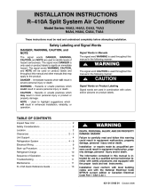
LIQUID LINE FILTER DRIER INSTALLATION
The filter drier (one is shipped with each 14ACX unit) must
be field installed in the liquid line between the outdoor unit’s
liquid line service valve and the indoor coil’s metering
device (fixed orifice or TXV) as illustrated in figure 7. This
filter drier must be installed to ensure a clean,
moisture−free system. Failure to install the filter drier will
void the warranty. A replacement filter drier is available
from Lennox. See Brazing Connections page 11 for
special procedures on brazing filter drier connections to
the liquid line.
OUTDOOR
UNIT
LIQUID LINE
SERVICE VALVE
LIQUID LINE
FILTER DRIER
LINE
LIQUID
LINE
BRAZE CONNECTION POINTS
F
igure 7. Typical Liquid Line Filter Drier Installation
Table 2. Refrigerant Line Set  Inches (mm)
Model Number
Valve Field Size Connections Recommended Line Set
Liquid Line Suction Line Liquid Line Suction Line L15 Series Line Sets
14ACX−018−230
3/8 in. (10 mm) 3/4 in. (19 mm) 3/8 in. (10 mm) 3/4 in. (19 mm)
L15−41  15 feet to 50 feet (4.6 meters to
15 meters)
14ACX−024−230
14ACX−030−230
14ACX−036−230
3/8 in. (10 mm) 7/8 in. (22 mm) 3/8 in. (10 mm) 7/8 in. (22 mm)
L15−65  15 feet to 50 feet (4.6 meters to
15 meters)
14ACX−041−230
14ACX−042−230
14ACX−047−230
14ACX−048−230
14ACX−059−230
3/8 in. (10 mm) 1−1/8 in. (29 mm) 3/8 in. (10 mm) 1−1/8 in. (29 mm) Field Fabricated
14ACX−060−230
NOTE  Some applications may required a field provided 7/8" to 1−1/8" adapter
Page 10
506645−01
ANCHORED HEAVY NYLON
WIRE TIE OR AUTOMOTIVE
MUFFLER-TYPE HANGER
STRAP LIQUID LINE TO
VAPOR LINE
WALL
STUD
LIQUID LINE
NON−CORROSIVE
METAL SLEEVE
VAPOR LINE − WRAPPED
IN ARMAFLEX
AUTOMOTIVE
MUFFLER-TYPE HANGER
REFRIGERANT LINE SET  TRANSITION
FROM VERTICAL TO HORIZONTAL
Line Set Isolation  The following illustrations are
examples of proper refrigerant line set isolation:
STRAPPING
MATERIAL (AROUND
VAPOR LINE ONLY)
TAPE OR
WIRE TIE
WIRE TIE (AROUND
VAPOR LINE ONLY)
FLOOR JOIST OR
ROOF RAFTER
TAPE OR
WIRE TIE
To hang line set from joist or rafter, use either metal strapping material
or anchored heavy nylon wire ties.
8 FEET (2.43 METERS)
STRAP THE VAPOR LINE TO THE JOIST
OR RAFTER AT 8 FEET (2.43 METERS)
INTERVALS THEN STRAP THE LIQUID
LINE TO THE VAPOR LINE.
FLOOR JOIST OR
ROOF RAFTER
REFRIGERANT LINE SET  INSTALLING
HORIZONTAL RUNS
NOTE  Similar installation practices should be used if line set is
to be installed on exterior of outside wall.
PVC
PIPE
FIBERGLASS
INSULATION
CAULK
OUTSIDE
WALL
VAPOR LINE WRAPPED
WITH ARMAFLEX
LIQUID
LINE
OUTSIDE WALL
LIQUID LINE
VAPOR LINE
WOOD BLOCK
BETWEEN STUDS
STRAP
WOOD BLOCK
STRAP
SLEEVE
WIRE TIE
WIRE TIE
WIRE TIE
INSIDE WALL
REFRIGERANT LINE SET  INSTALLING
VERTICAL RUNS (NEW CONSTRUCTION SHOWN)
INSTALLATION
LINE SET
NOTEInsulate liquid line when it is routed through areas where the
surrounding ambient temperature could become higher than the
temperature of the liquid line or when pressure drop is equal to or greater
than 20 psig.
NON−CORROSIVE
METAL SLEEVE
IMPORTANT  Refrigerant lines must not contact structure.
NON−CORROSIVE
METAL SLEEVE
8 FEET (2.43 METERS)
IMPORTANT  Refrigerant lines must not contact wall
Figure 8. Line Set Installation Guidelines
Page 11
14ACX SERIES
Brazing Connections
Use the procedures outline in figures 9 and 10 for brazing
line set connections to service valves.
IMPORTANT
Polyol ester (POE) oils used with HFC−410A
refrigerant absorb moisture very quickly. It is very
important that the refrigerant system be kept closed
as much as possible. DO NOT remove line set caps
or service valve stub caps until you are ready to make
connections.
WARNING
Danger of fire. Bleeding the refrigerant
charge from only the high side may result
in pressurization of the low side shell and
suction tubing. Application of a brazing
torch to a pressurized system may result
in ignition of the refrigerant and oil
mixture − Check the high and low
pressures before applying heat.
WARNING
When using a high pressure gas such as
dry nitrogen to pressurize a refrigeration
or air conditioning system, use a
regulator that can control the pressure
down to 1 or 2 psig (6.9 to 13.8 kPa).
CAUTION
Brazing alloys and flux contain materials which are
hazardous to your health.
Avoid breathing vapors or fumes from brazing
operations. Perform operations only in well−ventilated
areas.
Wear gloves and protective goggles or face shield to
protect against burns.
Wash hands with soap and water after handling brazing
alloys and flux.
IMPORTANT
Connect gauge set low pressure side to vapor line
service valve and repeat procedure starting at
paragraph 4 for brazing the liquid line to service port
valve.
IMPORTANT
Allow braze joint to cool before removing the wet rag
from the service valve. Temperatures above 250ºF can
damage valve seals.
IMPORTANT
Use silver alloy brazing rods with 5% minimum silver
alloy for copper−to−copper brazing. Use 45% minimum
alloy for copper−to−brass and copper−to−steel brazing.
WARNING
Fire, Explosion and Personal Safety
Hazard.
Failure to follow this warning could
result in damage, personal injury or
death.
Never use oxygen to pressurize or
purge refrigeration lines. Oxygen,
when exposed to a spark or open
flame, can cause fire and/or an ex-
plosion, that could result in property
damage, personal injury or death.
Page 12
506645−01
ATTACH THE MANIFOLD GAUGE SET FOR BRAZING LIQUID AND SUCTION / VAPOR LINE SERVICE
VALVES
OUTDOOR
UNIT
LIQUID LINE
VAPOR LINE
LIQUID LINE SERVICE
VALVE
SUCTION /
VAPOR LINE
SERVICE
VALVE
ATTACH
GAUGES
INDOOR
UNIT
SUCTION / VAPOR SERVICE PORT MUST BE
OPEN TO ALLOW EXIT POINT FOR NITROGEN
A Connect gauge set low pressure side to
liquid line service valve (service port).
B Connect gauge set center port to bottle of
nitrogen with regulator.
C Remove core from valve in suction / vapor
line service port to allow nitrogen to escape.
NITROGEN
HIGHLOW
USE REGULATOR TO FLOW
NITROGEN AT 1 TO 2 PSIG.
B
A
C
WHEN BRAZING LINE SET TO
SERVICE VALVES, POINT FLAME
AWAY FROM SERVICE VALVE.
Flow regulated nitrogen (at 1 to 2 psig) through the low−side refrigeration gauge set into the liquid line service port valve, and out of the suction /
vapor line service port valve.
CUT AND DEBUR
CAP AND CORE REMOVAL
Cut ends of the refrigerant lines square (free from nicks or dents)
and debur the ends. The pipe must remain round. Do not crimp end
of the line.
Remove service cap and core from
both the suction / vapor and liquid line
service ports.
1
2
LIQUID LINE SERVICE
VALVE
SERVICE
PORT
CORE
SERVICE PORT
CAP
SERVICE
PORT
CORE
SERVICE
PORT CAP
CUT AND DEBUR
LINE SET SIZE MATCHES
SERVICE VALVE CONNECTION
COPPER TUBE
STUB
SERVICE VALVE
CONNECTION
REFRIGERANT LINE
DO NOT CRIMP SERVICE VALVE
CONNECTOR WHEN PIPE IS
SMALLER THAN CONNECTION
REDUCER
3
SUCTION / VAPOR LINE
SERVICE VALVE
LINE SET SIZE IS SMALLER
THAN CONNECTION
Figure 9. Brazing Procedures
Page 13
14ACX SERIES
WHEN BRAZING LINE SET TO
SERVICE VALVES, POINT FLAME
AWAY FROM SERVICE VALVE.
LIQUID LINE SERVICE VALVE
LIQUID LINE
BRAZE LINE SET
Wrap both service valves with water saturated cloths as illustrated here and as mentioned in step 4, before brazing to line set. Water
saturated cloths must remain water saturated throughout the brazing and cool−down process.
WATER SATURATED
CLOTH
IMPORTANTAllow braze joint to cool. Apply
additional water saturated cloths to help cool brazed
joint. Do not remove water saturated cloths until piping
has cooled. Temperatures above 250ºF will damage
valve seals.
6
SUCTION / VAPOR LINE
WATER SATURATED
CLOTH
SUCTION / VAPOR LINE
SERVICE VALVE
After all connections have been brazed, disconnect manifold gauge set from service ports. Apply additional water saturated cloths to both
services valves to cool piping. Once piping is cool, remove all water saturated cloths. Refer to the unit installation instructions for the next step
in preparing the unit.
WHEN BRAZING LINE SET TO
SERVICE VALVES, POINT FLAME
AWAY FROM SERVICE VALVE.
PREPARATION FOR NEXT STEP
7
WARNING
1. FIRE, PERSONAL INJURY, OR PROPERTY
DAMAGE will result if you do not wrap a water
saturated cloth around both liquid and suction line
service valve bodies and copper tube stub while
brazing in the line set! The braze, when complete,
must be quenched with water to absorb any residual
heat.
2. Do not open service valves until refrigerant lines and
indoor coil have been leak−tested and evacuated.
Refer to procedures provided in this supplement.
WRAP SERVICE VALVES
To help protect service valve seals during brazing, wrap water saturated cloths around service valve bodies and copper tube stubs. Use
additional water saturated cloths underneath the valve body to protect the base paint.
4
FLOW NITROGEN
Flow regulated nitrogen (at 1 to 2 psig) through the refrigeration gauge set into the valve stem port connection on the liquid service valve and
out of the suction / vapor valve stem port. See steps 3A, 3B and 3C on manifold gauge set connections
5
Figure 10. Brazing Procedures (continued)
Page 14
506645−01
Flushing Line Set and Indoor Coil
Flushing is only required if existing indoor coil and line set are to be used. Otherwise proceed to Installing Indoor Metering
Device on page 15.
SENSING
LINE
TEFLON
®
RING
FIXED ORIFICE
BRASS NUT
LIQUID LINE ASSEMBLY
(INCLUDES STRAINER)
LIQUID LINE ORIFICE HOUSING
DISTRIBUTOR TUBES
DISTRIBUTOR
ASSEMBLY
REMOVE AND DISCARD
WHITE TEFLON
®
SEAL
(IF PRESENT)
A On fully cased coils, remove the coil access and plumbing panels.
B Remove any shipping clamps holding the liquid line and distributor as-
sembly.
C Using two wrenches, disconnect liquid line from liquid line orifice hous-
ing. Take care not to twist or damage distributor tubes during this pro-
cess.
D Remove and discard fixed orifice, valve stem assembly if present and
Teflon
®
washer as illustrated above.
E Use a field−provided fitting to temporary reconnect the liquid line to the
indoor unit’s liquid line orifice housing.
TYPICAL EXISTING FIXED ORIFICE
REMOVAL PROCEDURE (UNCASED
COIL SHOWN)
TYPICAL EXISTING EXPANSION VALVE REMOVAL
PROCEDURE (UNCASED COIL SHOWN)
TWO PIECE PATCH PLATE
(UNCASED COIL ONLY)
VAPOR
LINE
DISTRIBUTOR
ASSEMBLY
DISTRIBUTOR
TUBES
LIQUID
LINE
MALE EQUALIZER
LINE FITTING
EQUALIZER
LINE
CHECK
EXPANSION
VALVE
TEFLON
®
RING
STUB END
TEFLON
®
RING
SENSING BULB
LIQUID LINE
ORIFICE
HOUSING
LIQUID LINE
ASSEMBLY WITH
BRASS NUT
A On fully cased coils, remove the coil access and plumbing panels.
B Remove any shipping clamps holding the liquid line and distributor
assembly.
C Disconnect the equalizer line from the check expansion valve
equalizer line fitting on the vapor line.
D Remove the vapor line sensing bulb.
E Disconnect the liquid line from the check expansion valve at the liquid
line assembly.
F Disconnect the check expansion valve from the liquid line orifice
housing. Take care not to twist or damage distributor tubes during this
process.
G Remove and discard check expansion valve and the two Teflon
®
rings.
H Use a field−provided fitting to temporary reconnect the liquid line to the
indoor unit’s liquid line orifice housing.
LOW HIGH
EXISTING
INDOOR
UNIT
GAUGE
MANIFOLD
INVERTED HCFC−22
CYLINDER CONTAINS
CLEAN HCFC−22 TO BE
USED FOR FLUSHING.
LIQUID LINE SERVICE
VALVE
INLET
DISCHARGE
TANK
RETURN
CLOSED
OPENED
RECOVERY
CYLINDER
RECOVERY MACHINE
NEW
OUTDOOR
UNIT
VAPOR LINE
SERVICE VALVE
VAPOR
LIQUID
1
A Inverted HCFC−22 cylinder with clean refrigerant to the vapor service
valve.
B HCFC−22 gauge set (low side) to the liquid line valve.
C HCFC−22 gauge set center port to inlet on the recovery machine with an
empty recovery tank to the gauge set.
D Connect recovery tank to recovery machines per machine instructions.
CONNECT GAUGES AND EQUIPMENT FOR
FLUSHING PROCEDURE
A
B
C
D
B
OR
FLUSHING LINE SET
A Set the recovery machine for liquid recovery and start the
recovery machine. Open the gauge set valves to allow the
recovery machine to pull a vacuum on the existing system line
set and indoor unit coil.
B Invert the cylinder of clean HCFC−22 and open its valve to allow
liquid refrigerant to flow into the system through the vapor line
valve. Allow the refrigerant to pass from the cylinder and through
the line set and the indoor unit coil before it enters the recovery
machine.
C After all of the liquid refrigerant has been recovered, switch the
recovery machine to vapor recovery so that all of the HCFC−22
vapor is recovered. Allow the recovery machine to pull down to 0
the system.
D Close the valve on the inverted HCFC−22 drum and the gauge
set valves. Pump the remaining refrigerant out of the recovery
machine and turn the machine off.
The line set and indoor unit coil must be flushed with at least the
same amount of clean refrigerant that previously charged the
system. Check the charge in the flushing cylinder before
proceeding.
1A
2
3
1B
Figure 11. Removing Metering Device and Flushing
Page 15
14ACX SERIES
Installing Indoor Metering Device
This outdoor unit is designed for use in systems that use
either an fixed orifice (RFC) (included with outdoor unit), or
expansion valve metering device (purchased separately)
at the indoor coil.
See the Lennox 14ACX Engineering Handbook for
approved expansion valve kit match ups. The expansion
valve unit can be installed internal or external to the indoor
coil. In applications where an uncased coil is being
installed in a field−provided plenum, install the expansion
valve in a manner that will provide access for field servicing
of the expansion valve. Refer to below illustration for
reference during installation of expansion valve unit. .
After installation of the indoor coil metering device,
proceed to Leak Test Line Set and Indoor Coil on page 16.
A Attach the vapor line sensing bulb in the proper
orientation as illustrated to the right using the clamp and
screws provided.
NOTE  Confirm proper thermal contact between vapor line
and expansion bulb before insulating the sensing bulb once
installed.
B Connect the equalizer line from the expansion valve to
the equalizer vapor port on the vapor line. Finger tighten
the flare nut plus 1/8 turn (7 ft−lbs) as illustrated below.
TWO PIECE
PATCH PLATE
(UNCASED
COIL ONLY)
VAPOR
LINE
LIQUID LINE
ORIFICE
HOUSING
DISTRIBUTOR
TUBES
LIQUID LINE
MALE EQUALIZER LINE
FITTING (SEE
EQUALIZER LINE
INSTALLATION FOR
FURTHER DETAILS)
SENSING
LINE
EQUALIZER
LINE
EXPANSION
VALVE
TEFLON
®
RING
(Uncased Coil Shown)
Sensing bulb insulation is required if
mounted external to the coil casing. sensing
bulb installation for bulb positioning.
STUB
END
TEFLON
®
RING
LIQUID LINE
ASSEMBLY WITH
BRASS NUT
DISTRIBUTOR
ASSEMBLY
A Remove the field−provided fitting that temporary
reconnected the liquid line to the indoor unit’s distributor
assembly.
B Install one of the provided Teflon
®
rings around the
stubbed end of the expansion valve and lightly lubricate
the connector threads and expose surface of the Teflon
®
ring with refrigerant oil.
C Attach the stubbed end of the expansion valve to the
liquid line orifice housing. Finger tighten and use an
appropriately sized wrench to turn an additional 1/2 turn
clockwise as illustrated in the figure above, or 20 ft−lb.
D Place the remaining Teflon
®
washer around the other
end of the expansion valve. Lightly lubricate connector
threads and expose surface of the Teflon
®
ring with
refrigerant oil.
E Attach the liquid line assembly to the expansion valve.
Finger tighten and use an appropriately sized wrench to
turn an additional 1/2 turn clockwise as illustrated in the
figure above or 20 ft−lb.
ON 7/8" AND LARGER LINES,
MOUNT SENSING BULB AT
EITHER THE 4 OR 8 O’CLOCK
POSITION. NEVER MOUNT ON
BOTTOM OF LINE.
12
ON LINES SMALLER THAN
7/8", MOUNT SENSING
BULB AT EITHER THE 3 OR
9 O’CLOCK POSITION.
12
BULB
VAPOR LINE
VAPOR LINE
NOTE  NEVER MOUNT ON BOTTOM OF LINE.
BULB
BULB
BULB
VAPOR LINE
FLARE NUT
COPPER FLARE
SEAL BONNET
MALE BRASS EQUALIZER
LINE FITTING
FLARE SEAL CAP
OR
1
2
3
4
5
6
7
8
9
10
11
12
1/2 Turn
SENSING BULB INSTALLATION
EQUALIZER LINE INSTALLATION
1
2
3
4
5
6
7
8
9
10
11
12
1/8 Turn
A Remove and discard either the flare seal cap or flare nut
with copper flare seal bonnet from the equalizer line port
on the vapor line as illustrated in the figure to the right.
B Remove and discard either the flare seal cap or flare nut
with copper flare seal bonnet from the equalizer line port on
the vapor line as illustrated in the figure to the right.
INDOOR EXPANSION VALVE INSTALLATION
Figure 12. Installing Indoor Expansion Valve
Page 16
506645−01
IMPORTANT
The Environmental Protection Agency (EPA) prohibits
the intentional venting of HFC refrigerants during
maintenance, service, repair and disposal of appliance.
Approved methods of recovery, recycling or reclaiming
must be followed.
IMPORTANT
If this unit is being matched with an approved line set
or indoor unit coil which was previously charged with
mineral oil, or if it is being matched with a coil which
was manufactured before January of 1999, the coil
and line set must be flushed prior to installation. Take
care to empty all existing traps. Polyol ester (POE) oils
are used in Lennox units charged with HFC−410A
refrigerant. Residual mineral oil can act as an
insulator, preventing proper heat transfer. It can also
clog the expansion device, and reduce the system
performance and capacity.
Failure to properly flush the system per the
instructions below will void the warranty.
Leak Test Line Set and Indoor Coil
IMPORTANT
Leak detector must be capable of sensing HFC
refrigerant.
After completing the leak testing the line set and indoor coil
as outlined in figure 13, proceed to Evacuating Line Set
and Indoor Coil on page 17.
WARNING
When using a high pressure gas such as
dry nitrogen to pressurize a refrigeration
or air conditioning system, use a
regulator that can control the pressure
down to 1 or 2 psig (6.9 to 13.8 kPa).
WARNING
Refrigerant can be harmful if it is inhaled. Refrigerant
must be used and recovered responsibly.
Failure to follow this warning may result in personal injury
or death.
TO VAPOR
SERVICE VALVE
HFC−410A
MANIFOLD GAUGE SET
OUTDOOR UNIT
HIGHLOW
NITROGEN
A With both manifold valves closed, connect the cylinder of HFC−410A refrigerant to the center port of the manifold gauge set. Open the valve
on the HFC−410A cylinder (vapor only).
B Open the high pressure side of the manifold to allow HFC−410A into the line set and indoor unit. Weigh in a trace amount of HFC−410A. [A
trace amount is a maximum of two ounces (57 g) refrigerant or three pounds (31 kPa) pressure]. Close the valve on the HFC−410A cylinder
and the valve on the high pressure side of the manifold gauge set. Disconnect the HFC−410A cylinder.
C Connect a cylinder of dry nitrogen with a pressure regulating valve to the center port of the manifold gauge set.
D Adjust dry nitrogen pressure to 150 psig (1034 kPa). Open the valve on the high side of the manifold gauge set in order to pressurize the line set
and the indoor unit.
E After a few minutes, open one of the service valve ports and verify that the refrigerant added to the system earlier is measurable with a leak
detector.
F After leak testing disconnect gauges from service ports.
After the line set has been connected to the indoor and outdoor units, check the line set connections and indoor unit for leaks. Use the
following procedure to test for leaks:
A Connect an HFC−410A manifold gauge set high pressure
hose to the vapor valve service port.
NOTE  Normally, the high pressure hose is connected to
the liquid line port. However, connecting it to the vapor port
better protects the manifold gauge set from high pressure
damage.
B With both manifold valves closed, connect the cylinder of
HFC−410A refrigerant to the center port of the manifold gauge
set.
NOTE  Later in the procedure,
the HFC−410A container will be
replaced by the nitrogen
container.
1
CONNECT GAUGE SET
2
TEST FOR LEAKS
A
B
Figure 13. Leak Test
Page 17
14ACX SERIES
Evacuating Line Set and Indoor Coil
A Open both manifold valves and start the vacuum pump.
B Evacuate the line set and indoor unit to an absolute pressure of 23,000 microns (29.01 inches of mercury).
NOTE  During the early stages of evacuation, it is desirable to close the manifold gauge valve at least once. A rapid rise in pressure
indicates a relatively large leak. If this occurs, repeat the leak testing procedure.
NOTE  The term absolute pressure means the total actual pressure within a given volume or system, above the absolute zero of
pressure. Absolute pressure in a vacuum is equal to atmospheric pressure minus vacuum pressure.
C When the absolute pressure reaches 23,000 microns (29.01 inches of mercury), perform the following:
Close manifold gauge valves
Close valve on vacuum pump
Turn off vacuum pump
Disconnect manifold gauge center port hose from vacuum pump
Attach manifold center port hose to a dry nitrogen cylinder with pressure regulator set to 150 psig (1034 kPa) and purge the hose.
Open manifold gauge valves to break the vacuum in the line set and indoor unit.
Close manifold gauge valves.
D Shut off the dry nitrogen cylinder and remove the manifold gauge hose from the cylinder. Open the manifold gauge valves to release the
dry nitrogen from the line set and indoor unit.
E Reconnect the manifold gauge to the vacuum pump, turn the pump on, and continue to evacuate the line set and indoor unit until the
absolute pressure does not rise above 500 microns (29.9 inches of mercury) within a 20−minute period after shutting off the vacuum pump
and closing the manifold gauge valves.
F When the absolute pressure requirement above has been met, disconnect the manifold hose from the vacuum pump and connect it to an
upright cylinder of HFC−410A refrigerant. Open the manifold gauge valve 1 to 2 psig in order to release the vacuum in the line set and
indoor unit.
G Perform the following:
OUTDOOR
UNIT
TO VAPOR
SERVICE VALVE
TO LIQUID LINE
SERVICE VALVE
MICRON
GAUGE
VACUUM PUMP
A34000 1/4 SAE TEE WITH
SWIVEL COUPLER
500
MANIFOLD
GAUGE SET
HFC−410A
RECOMMEND
MINIMUM 3/8" HOSE
A Connect low side of manifold gauge set
with 1/4 SAE in−line tee to vapor line
service valve
B Connect high side of manifold gauge
set to liquid line service valve
C Connect micron gauge available
connector on the 1/4 SAE in−line tee.
D Connect the vacuum pump (with
vacuum gauge) to the center port of the
manifold gauge set. The center port
line will be used later for both the
HFC−410A and nitrogen containers.
HIGH
LOW
1
2
3
4
5
6
7
8
9
10
11
12
1/6 TURN
NITROGEN
1
CONNECT GAUGE SET
A
B
C
D
2
EVACUATE THE SYSTEM
NOTE  Remove cores from service valves (if not already done).
Close manifold gauge valves.
Shut off HFC−410A cylinder.
Reinstall service valve cores by removing manifold hose from service valve. Quickly install cores with core
tool while maintaining a positive system pressure.
Replace stem caps and secure finger tight, then tighten an additional one−sixth (1/6) of a turn as illustrated.
Figure 14. Evacuating System
Page 18
506645−01
WARNING
Danger of Equipment Damage. Avoid deep vacuum
operation. Do not use compressors to evacuate a
system. Extremely low vacuums can cause internal
arcing and compressor failure. Damage caused by
deep vacuum operation will void warranty.
CAUTION
Brazing alloys and flux contain materials which are
hazardous to your health.
Avoid breathing vapors or fumes from brazing
operations. Perform operations only in well ventilated
areas.
Wear gloves and protective goggles or face shield to
protect against burns.
Wash hands with soap and water after handling brazing
alloys and flux.
Evacuating the system of non−condensables is critical for
proper operation of the unit. Non−condensables are
defined as any gas that will not condense under
temperatures and pressures present during operation of
an air conditioning system. Non−condensables and water
suction combine with refrigerant to produce substances
that corrode copper piping and compressor parts.
IMPORTANT
Use a thermocouple or thermistor electronic vacuum
gauge that is calibrated in microns. Use an instrument
capable of accurately measuring down to 50 microns.
Electrical
In the U.S.A., wiring must conform with current local codes
and the current National Electric Code (NEC). In Canada,
wiring must conform with current local codes and the current
Canadian Electrical Code (CEC).
Refer to the furnace or air handler installation instructions
for additional wiring application diagrams and refer to unit
nameplate for minimum circuit ampacity and maximum
overcurrent protection size.
24VAC TRANSFORMER
Use the transformer provided with the furnace or air
handler for low-voltage control power (24VAC − 40 VA
minimum)
Refer to the unit nameplate for minimum circuit ampacity, and maximum
fuse or circuit breaker (HACR per NEC). Install power wiring and properly
sized disconnect switch.
NOTE  Units are approved for use only with copper conductors.
Ground unit at disconnect switch or to an earth ground.
SIZE CIRCUIT AND INSTALL SERVICE
DISCONNECT SWITCH
NOTE  24VAC, Class II circuit connections are made in the control
panel.
Install room thermostat (ordered separately) on an inside wall
approximately in the center of the conditioned area and 5 feet (1.5m) from
the floor. It should not be installed on an outside wall or where it can be
affected by sunlight or drafts.
THERMOSTAT
5 FEET
(1.5M)
INSTALL THERMOSTAT
SERVICE
DISCONNECT
SWITCH
MAIN FUSE BOX/
BREAKER PANEL
WARNING
Electric Shock Hazard. Can cause injury or death. Unit must be grounded in accordance with national and
local codes.
Line voltage is present at all components when unit is not in operation on units with single-pole contactors.
Disconnect all remote electric power supplies before opening access panel. Unit may have multiple power
supplies.
Page 19
14ACX SERIES
Any excess high voltage field wiring should be trimmed and
secured away from any low voltage field wiring. To facilitate a
conduit, a cutout is located in the bottom of the control panel.
Connect conduit to the control panel using a proper conduit fitting.
ROUTING HIGH VOLTAGE/ GROUND AND CONTROL WIRING
HIGH VOLTAGE
FIELD WIRING
LOW VOLTAGE
FIELD WIRING
FACTORY
WIRING
WIRE RUN LENGTH AWG# INSULATION TYPE
LESS THAN 100’ (30 METERS) 18 TEMPERATURE RATING
MORE THAN 100’ (30 METERS) 16 35ºC MINIMUM.
Install low voltage wiring from outdoor to indoor unit and from thermostat
to indoor unit as illustrated.
HIGH VOLTAGE / GROUND WIRES
LOW VOLTAGE CONTROL WIRING
A Run 24VAC control wires through hole with grommet and secure with
provided wire tie.
B Make 24VAC thermostat wire connections. Locate the two wires from the
contactor and make connection using field provided wire nuts:
S Yellow to Y1
S Black to C (common)
NOTE  For proper voltages, select thermostat wire (control wires)
gauge per table above.
NOTE  Wire tie provides low voltage control wire strain relief and to
maintain separation of field installed low and high voltage circuits.
W1
Y
G
C
R
Y
G
C
THERMOSTAT
INDOOR UNIT
POWER
HEAT
COOLING
INDOOR
BLOWER
COMMON
OUTDOOR
UNIT
Y1
C
W
R
SINGLE PHASE
NOTEDo not bundle any excess 24VAC control wires inside
control panel.
CONTROL
WIRING
HIGH VOLTAGE
CONNECTIONS
(CONTACTOR)
GROUND
GROMMET AND
WIRE TIE
HIGH VOLTAGE
FLEXIBLE
CONDUIT
A
B
YELLOW
BLACK
Figure 15. Typical Field Wiring Diagram
Page 20
506645−01
HIGH PRESSURE SWITCH
(S4)  LIQUID LINE
CRANKCASE THERMOSTAT (S40)
CRANKCASE HEATER (HR1)
Figure 16. Typical Factory Wiring Diagram (Copeland Compressor)
  • Page 1 1
  • Page 2 2
  • Page 3 3
  • Page 4 4
  • Page 5 5
  • Page 6 6
  • Page 7 7
  • Page 8 8
  • Page 9 9
  • Page 10 10
  • Page 11 11
  • Page 12 12
  • Page 13 13
  • Page 14 14
  • Page 15 15
  • Page 16 16
  • Page 17 17
  • Page 18 18
  • Page 19 19
  • Page 20 20
  • Page 21 21
  • Page 22 22
  • Page 23 23
  • Page 24 24
  • Page 25 25
  • Page 26 26
  • Page 27 27
  • Page 28 28
  • Page 29 29
  • Page 30 30

Lennox 14ACX User manual

Category
Split-system air conditioners
Type
User manual

Ask a question and I''ll find the answer in the document

Finding information in a document is now easier with AI