
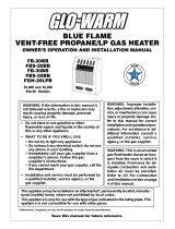
BLUE-FLAME VENT-FREE
PROPANE GAS HEATER
OWNER’S OPERATION AND INSTALLATION MANUAL
Save this manual for future reference.
Heater Sizes: 18,000 BTU/Hr Non-Thermostat,
18,000 BTU/Hr Thermostat, and 28,000 BTU/Hr Thermostat
“A” Model Heaters
WARNING: If the information in this manual is not followed exactly, a fire or
explosion may result causing property damage, personal injury, or loss of life.
— Do not store or use gasoline or other flammable vapors and liquids in the
vicinity of this or any other appliance.
— WHAT TO DO IF YOU SMELL GAS
• Do not try to light any appliance.
• Do not touch any electrical switch; do not use any phone in your building.
• Immediately call your gas supplier from a neighbor’s phone. Follow the
gas supplier’s instructions.
• If you cannot reach your gas supplier, call the fire department.
— Installation and service must be performed by a qualified installer, service
agency, or the gas supplier.
®

2
099573
CONTENTS
SECTION PAGE
Safety Information.........................................................................2
Product Identification ....................................................................4
Local Codes ...................................................................................4
Unpacking......................................................................................4
Product Features ............................................................................4
Fresh Air For Combustion and Ventilation ...................................5
Installing To Wall..........................................................................9
Connecting To Gas Supply............................................................14
Checking Gas Connections............................................................15
Operating Heater (Thermostat Models).........................................17
Operating Heater (Non-Thermostat Model) ..................................20
Inspecting Burner ..........................................................................22
Cleaning And Maintenance ...........................................................24
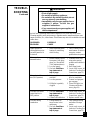
Troubleshooting.............................................................................24
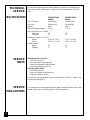
Technical Service ..........................................................................28
Specifications ................................................................................ 28
Service Hints .................................................................................28
Service Publications ......................................................................28
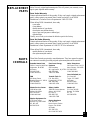
Replacement Parts .........................................................................29
Parts Centrals.................................................................................29
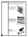
Accessories ....................................................................................30
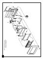
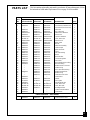
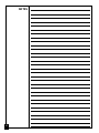
Illustrated Parts List.......................................................................31-32
Warranty Information .................................................................... Back Cover
SAFETY
INFORMATION
Safety Information continues on next page
WARNING ICON G 001
WARNINGS
IMPORTANT: Read this owner’s manual carefully and completely
before trying to assemble, operate, or service this heater. Improper
use of this heater can cause serious injury or death from burns, fire,
explosion, electrical shock, and carbon monoxide poisoning.
WARNING ICON G 001
DANGER
Carbon monoxide poisoning may lead to death!
Carbon Monoxide Poisoning: Early signs of carbon monoxide poisoning
resemble the flu, with headaches, dizziness, or nausea. If you have these signs, the
heater may not be working properly. Get fresh air at once! Have heater serviced.
Some people are more affected by carbon monoxide than others. These include
pregnant women, people with heart or lung disease or anemia, those under the
influence of alcohol, and those at high altitudes.
Propane Gas: Propane gas is odorless. An odor-making agent is added to
propane gas. The odor helps you detect a propane gas leak. However, the odor
added to propane gas can fade. Propane gas may be present even though no odor
exists.
Make certain you read and understand all Warnings. Keep this manual for
reference. It is your guide to safe and proper operation of this heater.

3
099573
SAFETY
INFORMATION
Continued
WARNING ICON G 001
WARNINGS
Continued
WARNING: Any change to this heater or its controls can be dangerous.
1. Use only propane gas. Do not convert heater to use different fuel type.
2. Do not place propane supply tank(s) inside any structure. Locate propane supply
tank(s) outdoors.
3. If you smell gas
• shut off gas supply
• do not try to light any appliance
• do not touch any electrical switch; do not use any phone in your building
• immediately call your gas supplier from a neighbor’s phone. Follow the gas
supplier’s instructions
• if you cannot reach your gas supplier, call the fire department
4. This heater shall not be installed in a bedroom or bathroom.
5. Never install the heater
• in a recreational vehicle
• where curtains, furniture, clothing, or other flammable objects are less than 36
inches from the front, top, or sides of the heater
• as a fireplace insert
• in high traffic areas
• in windy or drafty areas
6. This heater needs fresh, outside air ventilation to run properly. This heater has an
oxygen depletion sensor (ODS) pilot light safety system. The ODS shuts down the
heater if not enough fresh air is available. See Fresh Air for Combustion and
Ventilation, pages 5 through 8.
7. Never run heater in small, closed room. Open door into next room to help ventilate.
8. If heater shuts off, do not relight until you provide fresh, outside air. If heater keeps
shutting off, have it serviced.
9. Do not run heater
• where flammable liquids or vapors are used or stored
• under dusty conditions
10.Never place any objects on the heater.
11.Surface of heater becomes very hot when running heater. Keep children and adults
away from hot surface to avoid burns or clothing ignition. Heater will remain hot
for a time after shut-down. Allow surface to cool before touching.
12.Carefully supervise young children when they are in the room with heater.
13.Make sure grill guard is in place before running heater.
14.Do not use heater if any part has been under water. Immediately call a qualified
service technician to inspect the room heater and to replace any part of the control
system and any gas control which has been under water.
15. Turn off and unplug heater and let cool before servicing. Only a qualified service
person should service and repair heater.
16.Operating heater above elevations of 4,500 feet may cause pilot outage.

4
099573
PRODUCT
IDENTIFICATION
LOCAL CODES
Install and use heater with care. Follow all local codes. In the absence of local
codes, use the latest edition of The National Fuel Gas Code ANSI Z223, also
known as NFPA 54*.
*Available from:
American National Standards Institute, Inc.
1430 Broadway
New York, NY 10018
National Fire Protection Association, Inc.
Batterymarch Park
Quincy, MA 02269
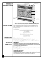
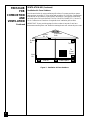
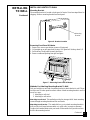
Figure 1 - Vent-Free Propane Gas Heater (28,000 BTU/Hr Model Shown)
UNPACKING
1. Remove heater from carton.
2. Remove all protective packaging applied to heater for shipment.
3. Check heater for any shipping damage. If heater is damaged, promptly inform
dealer where you bought heater.
PRODUCT
FEATURES
Safety Device
This heater has a pilot with an Oxygen Depletion Sensor Shutoff System (ODS).
The ODS/pilot is a required feature for vent-free room heaters. The ODS/pilot shuts
off the heater if there is not enough fresh air.
Piezo Ignition System
This heater has a piezo ignitor. This system requires no matches, batteries, or other
sources to light heater.
Thermostatic Heat Control
(Thermostat Models Only)
Thermostat models have a thermostat sensing bulb and a control valve. This results
in the greatest heater comfort. This can also result in lower gas bills.
Ignitor Button Control Knob
Heater
Cabinet
Front
Panel
Glass
Panel
Grill
Guard

5
099573
FRESH AIR
FOR
COMBUSTION
AND
VENTILATION
WARNING ICON G 001
WARNING
This heater must have fresh air for proper operation. If not, poor
fuel combustion could result. Read the following instructions to
insure proper fresh air for this and other fuel-burning appliances
in your home.
Today’s homes are built more energy efficient than ever. New materials, increased
insulation, and new construction methods help reduce heat loss in homes. Home
owners weather strip and caulk around windows and doors to keep the cold air out
and the warm air in. During heating months, home owners want their homes as
airtight as possible.
While it is good to make your home energy efficient, your home needs to breathe.
Fresh air must enter your home. All fuel-burning appliances need fresh air for
proper combustion and ventilation.
Exhaust fans, fireplaces, clothes dryers, and fuel burning appliances draw air from
the house to operate. You must provide adequate fresh air for these appliances.
This will insure proper venting of vented fuel-burning appliances.
PRODUCING ADEQUATE VENTILATION
All spaces in homes fall into one of the three following ventilation classifications:
1. Unusually Tight Contruction; 2. Unconfined Space; 3. Confined Space.
The information on pages 5 through 8 will help you classify your space and provide
adequate ventilation.
Unusually Tight Construction
The air that leaks around doors and windows may provide enough fresh air for
combustion and ventilation. However, in buildings of unusually tight construction,
you must provide additional fresh air.
Unusually tight construction is defined as construction where:
a. walls and ceilings exposed to the outside atmosphere have a continu-
ous water vapor retarder with a rating of one perm or less with open-
ings gasketed or sealed
and
b. weather stripping has been added on openable windows and doors
and
c. caulking or sealants are applied to areas such as joints around window
and door frames, between sole plates and floors, between wall-ceiling
joints, between wall panels, at penetrations for plumbing, electrical, and
gas lines, and at other openings.
If your home meets all of the three criteria above, you must provide addi-
tional fresh air. See
Ventilation Air From Outdoors
, page 8
.
If your home does not meet all of the three criteria above, continue reading.
Unconfined Space
An unconfined space has a minimum air volume of 50 cubic feet for each 1000
BTU/Hr input rating of all appliances in the space (cubic feet equals length x
width x height of space). Include adjoining rooms only if there are doorless
passageways or ventilation grills between the rooms.
Confined Space
A confined space has an air volume of less than 50 cubic feet for each 1000
BTU/Hr input rating of all appliances in the space (cubic feet equals length x
width x height of space). Include adjoining rooms only if there are doorless
passageways or ventilation grills between the rooms.
Continued

6
099573
FRESH AIR
FOR
COMBUSTION
AND
VENTILATION
Continued
WARNING ICON G 001
WARNING
You must provide additional ventilation air in a confined space.
DETERMINING FRESH-AIR FLOW FOR HEATER LOCATION
Determining if You Have a Confined or Unconfined Space
Use this worksheet to determine if you have a confined or unconfined space.
Space: Includes the room in which you will install heater plus any adjoining rooms with
doorless passageways or ventilation grills between the rooms.
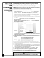
1. Determine the volume of the space (length x width x height).
Length x Width x Height = ___________________ cu. ft. (volume of space)
Example:
Space size 20 ft. (length) x 16 ft. (width) x 8 ft. (ceiling height) =
2560 cu. ft. (volume of space)
If additional ventilation to adjoining room is supplied with grills or openings, add the
volume of these rooms to the total volume of the space.
2. Divide the space volume by 50 cubic feet to determine the maximum BTU/Hr the space
can support.
____________ (volume of space) ÷ 50 cu. ft. = (Maximum BTU/Hr
the space can support)
Example:
2560 cu. ft. (volume of space) ÷ 50 cu. ft. = 51.2 or 51,200 (maximum
BTU/Hr the space can support)
3. Add the BTU/Hr of all fuel burning appliances in the space.
Vent-free heater ___________________ BTU/Hr
Gas water heater* ___________________ BTU/Hr
Gas furnace ___________________ BTU/Hr
Vented gas heater ___________________ BTU/Hr
Gas fireplace logs ___________________ BTU/Hr
Other gas appliances* + ___________________ BTU/Hr
Total = ___________________ BTU/Hr
Example:
Gas water heater 40,000 BTU/Hr
Vent-free heater + 18,000 BTU/Hr
Total = 58,000 BTU/Hr
* Do not include direct-vent gas appliances. Direct-vent draws combustion air from the
outdoors and vents to the outdoors.
4. Compare the maximum BTU/Hr the space can support with the actual amount of BTU/
Hr used.
_________________ BTU/Hr (maximum the space can support)
_________________ BTU/Hr (actual amount of BTU/Hr used)
Example:
51,200 BTU/Hr (maximum the space can support)
58,000 BTU/Hr (actual amount of BTU/Hr used)
The space in the above example is a confined space because the actual BTU/Hr used is
more than the maximum BTU/Hr the space can support. You must provide additional fresh
air. Your options are as follows:
A. Rework worksheet, adding the space of an adjoining room. If the extra space provides
an unconfined space, remove door to adjoining room or add ventilation grills between
rooms. See Ventilation Air From Inside Building, page 7.
B. Vent room directly to the outdoors. See Ventilation Air From Outdoors, page 8.
C. Install a lower BTU/Hr heater, if lower BTU/Hr size makes room unconfined.
If the actual BTU/Hr used is less than the maximum BTU/Hr the space can support, the
space is an unconfined space. You will need no additional fresh air ventilation.

7
099573
Or
Remove
Door into
Adjoining
Room,
Option 3
Ventilation Grills
Into Adjoining Room,
Option 2
12"
12"
Ventilation
Grills
into Adjoining
Room,
Option 1
FRESH AIR
FOR
COMBUSTION
AND
VENTILATION
Continued
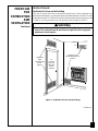
VENTILATION AIR
Ventilation Air From Inside Building
This fresh air would come from an adjoining unconfined space. When ventilating to an
adjoining unconfined space, you must provide two permanent openings: one within 12" of the
ceiling and one within 12" of the floor on the wall connecting the two spaces (see options 1 and
2, Figure 2). You can also remove door into adjoining room (see option 3, Figure 2).
WARNING ICON G 001
WARNING
Rework worksheet, adding the space of the adjoining unconfined
space.
The combined spaces must have enough fresh air to supply all
appliances in both spaces.
Figure 2 - Ventilation Air from Inside Building
Continued

8
099573
FRESH AIR
FOR
COMBUSTION
AND
VENTILATION
Continued
VENTILATION AIR
(Continued)
Ventilation Air From Outdoors
Provide extra fresh air by using ventilation grills or ducts. You must provide two perma-
nent openings: one within 12" of the ceiling and one within 12" of the floor. Connect these
items directly to the outdoors or spaces open to the outdoors. These spaces include attics
and crawl spaces. Follow the National Fuel Gas Code NFPA 54/ANSI Z223.1, Section 5.3,
Air for Combustion and Ventilation for required size of ventilation grills or ducts.
IMPORTANT:
Do not provide openings for inlet or outlet air into attic if attic has a
thermostat-controlled power vent. Heated air entering the attic will activate the power vent.
Figure 3 - Ventilation Air from Outdoors
Outlet
Air
Ventilated
Attic
Outlet
Air
Inlet
Air
Inlet Air
Ventilated
Crawl Space
To
Crawl
Space
To Attic

9
099573
INSTALLING
TO WALL
NOTICE
A qualified service person must install heater. Follow all local codes.
CHECK GAS TYPE
Use only propane gas. If your gas supply is not propane, do not install heater. Call
dealer where you bought heater for proper type heater.
INSTALLATION ITEMS
Before installing heater, make sure you have the items listed below.
• external regulator (supplied by
installer, see page 14)
• piping (check local codes)
• sealant (resistant to propane gas)
• manual shutoff valve *
• ground joint union
• test gauge connection * (see
Figure 14, page 15)
• sediment trap
• tee joint
• pipe wrench
* An A.G.A. design-certified manual shutoff valve with 1/8" NPT tap is an acceptable
alternative to test gauge connection. Purchase the optional A.G.A. design-certified
manual shutoff valve from your dealer. See Accessories, page 30.
LOCATING HEATER
This heater is designed to be mounted on a wall.
WARNING ICON G 001
WARNING
Maintain the minimum clearances shown in Figure 4 (page 10). If
you can, provide greater clearances from floor, ceiling, and join-
ing wall.
You can locate heater on floor, away from a wall. An optional floor mounting stand
is needed. Purchase the floor mounting stand from your dealer. See Accessories,
page 30.
WARNING ICON G 001
WARNING
Never install the heater
• in a bedroom or bathroom
• in a recreational vehicle
• where curtains, furniture, clothing, or other flammable objects are
less than 36 inches from the front, top, or sides of the heater
• as a fireplace insert
• in high traffic areas
• in windy or drafty areas
Continued
WARNING ICON G 001
CAUTION
This heater creates warm air currents. These currents move heat
to wall surfaces next to heater. Installing heater next to vinyl or
cloth wall coverings or operating heater where impurities in the air
(such as tobacco smoke) exist, may discolor walls.
IMPORTANT:
Vent-free heaters add moisture to the air. Although this is beneficial,
installing heater in rooms without enough ventilation air may cause mildew to form
from too much moisture. See Fresh Air for Combustion and Ventilation, pages 5
through 8.

10
099573
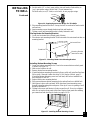
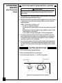
Figure 5 - Attaching Thermostat Sensing Bulb
For convenience and efficiency, install heater
• where there is easy access for operation, inspection, and service
• in coldest part of room
An optional fan kit is available from your dealer. See Accessories, page 30. If
planning to use fan, locate heater near an electrical outlet.
THERMOSTAT SENSING BULB
(Thermostat Models Only)
The thermostat sensing bulb has been placed inside the heater for protection during
shipping.
Locating Thermostat Sensing Bulb
1. Remove front panel of heater (see Figure 7, page 11).
2. Locate thermostat sensing bulb just under burner assembly.
IMPORTANT:
Attach thermostat sensing bulb to back of heater for proper operation.
Attaching Thermostat Sensing Bulb
1. Remove thermostat sensing bulb from holders inside heater. Route through slot
opening in bottom of heater.
2. Place clamp on thermostat sensing bulb as shown in Figure 5. Clamp is provided
in hardware package.
3. Snap clamp into upper mounting hole as shown in Figure 5. Mounting hole is
located on lower left edge on back of heater. Make sure the thermostat sensing
bulb is pointing up.
Figure 4 - Mounting Clearances As Viewed From Front of Heater
INSTALLING
TO WALL
Continued
Clamp
Thermostat
Sensing Bulb
WARNING ICON G 001
CAUTION
If you install the heater in a home garage
• heater pilot and burner must be at least 18 inches above floor
• locate heater where moving vehicle will not hit it
Minimum
From
Sides Of
Heater
36"
3"
FLOOR
CEILING
Minimum
Minimum To Top Surface
Of Carpeting, Tile Or Other
Combustible Material
6"
Left
Side
Right
Side

11
099573
Mounting
Bracket
Removing Front Panel Of Heater
1. Remove two screws near bottom corners of front panel.
2. Lift straight up on grill guard until it stops. Grill guard will slide up about 1/4".
3. Pull bottom of front panel forward, then down.
4. Remove cardboard packing from grill and glass.
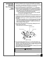
Methods For Attaching Mounting Bracket To Wall
Only use last hole on each end of mounting bracket to attach bracket to wall. These
two holes are 16 inches apart from their centers. Attach mounting bracket to wall in
one of two ways.
1. Attaching to wall stud
2. Attaching to wall anchor
Attaching to wall stud This method provides the strongest hold. Insert mounting
screws through mounting bracket and into wall studs.
Attaching to wall anchor This method allows you to attach mounting bracket to
hollow walls (wall areas between studs) or to solid walls (concrete or masonry).
Decide which method better suits your needs. Either method will provide a secure
hold for the mounting bracket.
INSTALLING HEATER TO WALL
Mounting Bracket
The mounting bracket is located on back panel of heater. It has been taped there for
shipping. Remove mounting bracket from back panel.
Figure 6 - Bracket Location
Figure 7 - Removing Front Panel Of Heater
INSTALLING
TO WALL
Continued
Continued

12
099573
Marking Screw Locations
1. Tape mounting bracket to wall where heater will be located. Make sure mount-
ing bracket is level.
28,000 BTU/Hr Model 18,000 BTU/Hr Models
2. Mark screw locations on wall (see Figure 8).
Note:
Only mark last hole on each end of mounting bracket. Insert mounting
screws through these holes only.
3. Remove tape and mounting bracket from wall.
Attaching Mounting Bracket To Wall
Note:
Wall anchors, mounting screws, and spacers are in hardware package. The
hardware package is provided with heater.
Attaching to wall stud method
For attaching mounting bracket to wall studs
1. Drill holes at marked locations using 9/64" drill bit.
2. Place mounting bracket onto wall. Line up last hole on each end of bracket with
holes drilled in wall.
3. Insert mounting screws through bracket and into wall studs.
4. Tighten screws until mounting bracket is firmly fastened to wall studs.
Attaching to wall anchor method
For attaching mounting bracket to hollow walls (wall areas between studs) or solid
walls (concrete or masonry)
1. Drill holes at marked locations using 5/16" drill bit. For solid walls (concrete or
masonry), drill at least 1" deep.
2. Fold wall anchor as shown in Figure 9.
3. Insert wall anchor (wings first) into hole. Tap anchor flush to wall.
Figure 8 - Mounting Bracket Clearances
INSTALLING
TO WALL
Continued
Figure 9 - Folding Anchor
WARNING ICON G 001
WARNING
Maintain minimum clearances shown in Figure 8. If you can, pro-
vide greater clearances from floor and joining wall.
18 3/4"
Min.
11"
Min.
16"
18 3/4"
Min.
7 1/4"
Min.
Adjoining Wall
16"
Adjoining Wall
Only Insert Mounting
Screws Through Last
Hole On Each End
Only Insert Mounting
Screws Through Last
Hole On Each End
Floor
Floor

13
099573
4. For thin walls (1/2" or less), insert red key into wall anchor. Push red key to
“pop” open anchor wings.
IMPORTANT:
Do not hammer key!
For thick walls (over 1/2" thick) or solid walls, do not pop open wings.
Figure 10 - Popping Open Anchor Wings For Thin Walls
5. Place mounting bracket onto wall. Line up last hole on each end of bracket with
wall anchors.
6. Insert mounting screws through bracket and into wall anchors.
7. Tighten screws until mounting bracket is firmly fastened to wall.
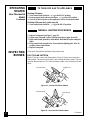
Placing Heater On Mounting Bracket
1. Locate two horizontal slots on back panel of heater.
2. Place heater onto mounting bracket. Slide horizontal slots onto stand-out tabs on
mounting bracket.
Figure 12 - Installing Bottom Mounting Screws
Stand-Out Tab
Horizontal Slots
Mounting Bracket
(attached to wall)
Installing Bottom Mounting Screws
1. Locate two bottom mounting holes. These holes are near bottom on back panel
of heater (see Figure 12).
2. Mark screw locations on wall.
3. Remove heater from mounting bracket.
4. If installing bottom mounting screws into hollow or solid wall, install wall anchors.
Follow steps 1 through 4 under Attaching To Wall Anchor Method, page 12.
If installing bottom mounting screw into wall stud, drill holes at marked loca-
tions using 9/64" drill bit.
5. Replace heater onto mounting bracket.
6. Place spacers between bottom mounting holes and wall anchor or drilled hole.
7. Hold spacer in place with one hand. With other hand, insert mounting screw
through bottom mounting hole and spacer. Place tip of screw in opening of wall
anchor or drilled hole.
8. Tighten both screws until heater is firmly secured to wall. Do not over tighten.
Note:
Do not replace front panel at this time. Replace front panel after making
gas connections and checking for leaks (see pages 14-16).
Figure 11 - Mounting Heater Onto Mounting Bracket
INSTALLING
TO WALL
Continued

14
099573
CONNECTING
TO GAS
SUPPLY
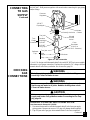
The installer must supply an external regulator. The external regulator will reduce
incoming gas pressure. You must reduce incoming gas pressure to between 11 and
14 inches of water. If you do not reduce incoming gas pressure, heater regulator
damage could occur. Install external regulator with the vent pointing down as
shown in Figure 13. Pointing the vent down protects it from freezing rain or sleet.
NOTICE
A qualified service person must connect heater to gas supply.
Follow all local codes.
Propane
Supply Tank
Figure 13 - External Regulator With Vent Pointing Down
Typical Pipe Diameters
18,000 BTU/Hr Models 3/8" or greater
28,000 BTU/Hr Model 1/2" or greater
Installation must include a manual shutoff valve, union, and plugged 1/8" NPT tap.
Locate NPT tap within reach for test gauge hook up. NPT tap must be upstream
from heater (see Figure 14, page 15).
Apply pipe joint sealant lightly to male threads. This will prevent excess sealant
from going into pipe. Excess sealant in pipe could result in clogged heater valves.
Install sediment trap in supply line as shown in Figure 14, page 15. Locate sediment
trap where it is within reach for cleaning. Locate sediment trap where trapped
matter is not likely to freeze. A sediment trap traps moisture and contaminants. This
keeps them from going into heater controls. If sediment trap is not installed or is
installed wrong, heater may not run properly.
WARNING ICON G 001
CAUTION
Never connect heater directly to the propane supply. This heater
requires an external regulator (not supplied). Install the external
regulator between the heater and propane supply.
WARNING ICON G 001
CAUTION
Use only new, black iron or steel pipe. Internally-tinned copper
tubing may be used in certain areas. Check your local codes. Use
pipe of large enough diameter to allow proper gas volume to heater.
If pipe is too small, undue loss of pressure will occur.
WARNING ICON G 001
CAUTION
Use pipe joint sealant that is resistant to liquid petroleum (LP) gas.
External
Regulator
Vent Pointing
Down

15
099573
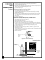
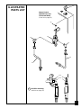
IMPORTANT:
Hold pressure regulator with wrench when connecting it to gas piping
and/or fittings.
Continued
Pressure
Regulator
Tee Joint
Reducer
Bushing to
1/8" NPT
1/8" NPT
Plug Tap
Test
Gauge
Connection *
Tee Joint
Pipe
Nipple
Cap
1/2" NPT
Pipe Nipple
Heater
Cabinet
Sediment
Trap
Manual
Shutoff
Valve *
3" Minimum
From
Gas Meter
(4" W.C. to
10.5" W.C. Pressure)
CONNECTING
TO GAS
SUPPLY
Continued
CHECKING
GAS
CONNECTIONS
PRESSURE TESTING GAS SUPPLY PIPING SYSTEM
Test Pressures In Excess Of 1/2 PSIG
1. Disconnect heater and its individual manual shutoff valve from gas supply
piping system. Pressures in excess of 1/2 psig will damage heater regulator.
2. Cap off open end of gas pipe where manual shutoff valve was connected.
* An A.G.A. design-certified manual shutoff valve with 1/8" NPT tap is an acceptable
alternative to test gauge connection. Purchase the optional A.G.A. design-certified
manual shutoff valve from your dealer. See Accessories, page 30.
WARNING ICON G 001
WARNING
Test all gas piping and connections for leaks after installing or
servicing. Correct all leaks at once.
WARNING ICON G 001
WARNING
Never use an open flame to check for a leak. Apply a mixture of
liquid soap and water to all joints. Bubbles forming show a leak.
Correct all leaks at once.
WARNING ICON G 001
CAUTION
Make sure external regulator has been installed between propane
supply and heater. See guidelines under
Connecting to Gas Sup-
ply
, page 14.
Figure 14 - Gas Connection
Ground Joint Union

16
099573
3. Pressurize supply piping system by either using compressed air or
opening propane supply tank valve.
4. Check all joints of gas supply piping system. Apply mixture of liquid soap and
water to gas joints. Bubbles forming show a leak.
5. Correct all leaks at once.
Test Pressures Equal To or Less Than 1/2 PSIG
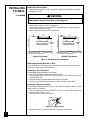
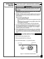
1. Close manual shutoff valve (see Figure 15).
2. Pressurize supply piping system by either using compressed air or opening
propane supply tank valve.
3. Check all joints from propane supply tank to manual shutoff valve (see Figure
16). Apply mixture of liquid soap and water to gas joints. Bubbles forming
show a leak.
4. Correct all leaks at once.
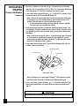
PRESSURE TESTING HEATER GAS CONNECTIONS
1. Open manual shutoff valve (see Figure 15).
2. Open propane supply tank valve.
3. Make sure control knob of heater is in the OFF position.
4. Check all joints from manual shutoff valve to thermostat gas valve (thermostat
models) or control valve (non-thermostat model) (see Figure 16). Apply mixture
of liquid soap and water to gas joints. Bubbles forming show a leak.
5. Correct all leaks at once.
6. Light heater (see Operating Heater, pages 17 through 22). Check all other
internal joints for leaks.
7. Turn off heater (see To Turn Off Gas to Appliance, page 19 [thermostat models]
or page 22 [non-thermostat model]).
8. Replace front panel.
CHECKING
GAS
CONNECTIONS
Continued
Figure 15 - Manual Shutoff Valve
Figure 16 - Checking Gas Joints
ON
POSITION
OFF
POSITION
Manual
Shutoff
Valve
Open
Closed
Thermostat Gas Valve or
Control Valve Location
Manual
Shutoff
Valve
Propane
Supply Tank

17
099573
OPERATING
HEATER
Thermostat Models
FOR YOUR SAFETY READ BEFORE LIGHTING
A. This appliance has a pilot which must be lighted by hand. When lighting
the pilot, follow these instructions exactly.
B. BEFORE LIGHTING smell all around the appliance area for gas. Be sure
to smell next to the floor because some gas is heavier than air and will
settle on the floor.
WHAT TO DO IF YOU SMELL GAS
• Do not try to light any appliance.
• Do not touch any electric switch; do not use any phone in your build-
ing.
• Immediately call your gas supplier from a neighbor’s phone. Follow
the gas supplier’s instructions.
• If you cannot reach your gas supplier, call the fire department.
C. Use only your hand to push in or turn the gas control knob. Never use
tools. If the knob will not push in or turn by hand, don’t try to repair it,
call a qualified service technician or gas supplier. Force or attempted
repair may result in a fire or explosion.
D. Do not use this appliance if any part has been under water. Immediately
call a qualified service technician to inspect the appliance and to replace
any part of the control system and any gas control which has been under
water.
Continued
WARNING ICON G 001
WARNING
If you do not follow these instructions exactly, a fire or explo-
sion may result causing property damage, personal injury or
loss of life.
LIGHTING INSTRUCTIONS
1. STOP! Read the safety information above.
2. Make sure manual shutoff valve is fully open.
3. Turn control knob clockwise
Clockwise
to the OFF position.
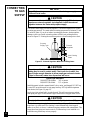
Figure 17 - Control Knob In The OFF Position
PILOT
LO
OFF
HI
IGNITOR
Ignitor Button
Control Knob

18
099573
4. Wait five (5) minutes to clear out any gas. Then smell for gas, including
near the floor. If you smell gas, STOP! Follow “B” in the safety information
at the top of page 17. If you don’t smell gas, go to the next step.
5. Turn control knob counterclockwise
C-clockwise
to the PILOT position. Press
in control knob for five (5) seconds (see Figure 17).
Note:
You may be running this heater for the first time after hooking up
to gas supply. If so, the control knob may need to be pressed in for 30
seconds. This will allow air to bleed from the gas system.
• If control knob does not pop up when released, contact a qualified
service person or gas supplier for repairs.
6. With control knob pressed in, push down and release ignitor button. This
will light pilot. The pilot is attached to the front of burner. The pilot can be
seen through the glass panel. If needed, keep pressing ignitor button until
pilot lights.
Note:
If pilot does not stay lit, refer to Troubleshooting, pages 24 through
27. Also contact a qualified service person or gas supplier for repairs.
Until repairs are made, light pilot with match. To light pilot with match,
see Manual Lighting Procedure, page 19.
7. Keep control knob pressed in for 30 seconds after lighting pilot. After 30
seconds, release control knob.
OPERATING
HEATER
Thermostat Models
Continued
Note:
If pilot goes out, repeat steps 3 through 7. This heater has a safety
interlock system. Wait one (1) minute before lighting pilot again.
8. Turn control knob counterclockwise
C-clockwise
to desired heating level. The
main burner should light. Set control knob to any heat level between HI
and LO.
Figure 18 - Pilot
Thermocouple
Ignitor Electrode
Pilot Burner
WARNING ICON G 001
CAUTION
Do not try to adjust heating levels by using the manual shutoff valve.

19
099573
TO TURN OFF GAS TO APPLIANCE
OPERATING
HEATER
Thermostat Models
Continued
Shutting Off Heater
1. Turn control knob clockwise
Clockwise
to the OFF position.
2. Turn off all electric power to the appliance if service is to be performed.
Shutting Off Burner Only (pilot stays lit)
1. Turn control knob clockwise
Clockwise
to the PILOT position.
THERMOSTAT CONTROL OPERATION
(Thermostat Models Only)
The thermostatic control used on these models differs from standard thermo-
stats. Standard thermostats simply turn on and off the burner. The thermostat
used on this heater senses the room temperature. The thermostat adjusts the
amount of gas flow to the burner. This increases or decreases the burner flame
height. At times the room may exceed the set temperature. If so, the burner
will shut off. The burner will cycle back on when room temperature drops
below the set temperature. The control knob can be set to any heat level
between HI and LO.
Note:
The thermostat sensing bulb measures the temperature of air near the
heater cabinet. This may not always agree with room temperature (depending
on housing construction, installation location, room size, open air tempera-
tures, etc.). Frequent use of your heater will let you determine your own
comfort levels.
MANUAL LIGHTING PROCEDURE
1. Remove front panel (see Figure 7, page 11).
2. Follow steps 1 through 5 under Lighting Instructions, pages 17 and 18.
3. With control knob pressed in, strike match. Hold match to pilot until pilot
lights.
4. Keep control knob pressed in for 30 seconds after lighting pilot. After 30
seconds, release control knob.
5. Replace front panel.

20
099573
OPERATING
HEATER
Non-Thermostat
Model
FOR YOUR SAFETY READ BEFORE LIGHTING
A. This appliance has a pilot which must be lighted by hand. When lighting
the pilot, follow these instructions exactly.
B. BEFORE LIGHTING smell all around the appliance area for gas. Be sure
to smell next to the floor because some gas is heavier than air and will
settle on the floor.
WHAT TO DO IF YOU SMELL GAS
• Do not try to light any appliance.
• Do not touch any electric switch; do not use any phone in your build-
ing.
• Immediately call your gas supplier from a neighbor’s phone. Follow
the gas supplier’s instructions.
• If you cannot reach your gas supplier, call the fire department.
C. Use only your hand to push in or turn the gas control knob. Never use
tools. If the knob will not push in or turn by hand, don’t try to repair it,
call a qualified service technician or gas supplier. Force or attempted
repair may result in a fire or explosion.
D. Do not use this appliance if any part has been under water. Immediately
call a qualified service technician to inspect the appliance and to replace
any part of the control system and any gas control which has been under
water.
WARNING ICON G 001
WARNING
If you do not follow these instructions exactly, a fire or explo-
sion may result causing property damage, personal injury or
loss of life.
LIGHTING INSTRUCTIONS
1. STOP! Read the safety information above.
2. Make sure manual shutoff valve is fully open.
3. Turn control knob clockwise
Clockwise
to the OFF position.
Figure 19 - Control Knob In The OFF Position
OFF
HIGH
PILOT
LOW
IGNITOR
Ignitor Button
Control Knob
Page is loading ...
Page is loading ...
Page is loading ...
Page is loading ...
Page is loading ...
Page is loading ...
Page is loading ...
Page is loading ...
Page is loading ...
Page is loading ...
Page is loading ...
Page is loading ...
Page is loading ...
Page is loading ...
Page is loading ...
Page is loading ...
-
 1
1
-
 2
2
-
 3
3
-
 4
4
-
 5
5
-
 6
6
-
 7
7
-
 8
8
-
 9
9
-
 10
10
-
 11
11
-
 12
12
-
 13
13
-
 14
14
-
 15
15
-
 16
16
-
 17
17
-
 18
18
-
 19
19
-
 20
20
-
 21
21
-
 22
22
-
 23
23
-
 24
24
-
 25
25
-
 26
26
-
 27
27
-
 28
28
-
 29
29
-
 30
30
-
 31
31
-
 32
32
-
 33
33
-
 34
34
-
 35
35
-
 36
36


Desa CGP26C Owner's manual
- Category
- Space heaters
- Type
- Owner's manual
Ask a question and I''ll find the answer in the document
Finding information in a document is now easier with AI
Related papers
-
Desa Tech GM280TLP Owner's manual
-
Comfort Glow CGP16R Owner's manual
-
Desa Tech VP1600IT User manual
-
 Vanguard Managed Solutions VP1000B User manual
-
Desa Tech VMH2800TP Owner's manual
-
-
-
Desa CGN18R User manual
-
-

Other documents
-
Vanguard Heating VP1600D User manual
-
-
Empire Comfort Systems HR30MN User guide
-
Procom ML100TBAHR User manual
-
-
-
 Glo-warm AFBS-30BBR User manual
-
FMI MBP30TLB User manual
-
-
World Marketing of America N185 User manual
