Kenmore 11080754001 User manual
- Category
- Washing machines
- Type
- User manual

®
24-Inch Wide
LAUNDRY CENTER
Washer- Electric Dryer
f
CENTRO DE LAVANDERIA
de 24 pulg. (61 cm) de ancho
Lavadora - Secadora el_ctrica
3979332A Sears Roebuck and Co., Hoffman Estates, IL 60179 U.S.A. www.sears.com

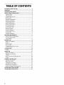
TABLE OF CONTENTS
WE SERVICE WHAT WE SELL ...................................................... 3
WARRANTY ..................................................................................... 3
WASHER/DRYER SAFETY ............................................................ 4
INSTALLATION INSTRUCTIONS .................................................. 5
Tools and Parts ............................................................................ 5
Alternate Parts .............................................................................. 5
Location Requirements ............................................................... 5
Drain System ................................................................................ 6
Electrical Requirements ................................................................ 7
Electrical Connection ................................................................... 8
Venting Requirements ............................................................... 12
Install Leveling Legs .................................................................. 13
Remove Foam Packing ............................................................. 13
Connect Drain Hose .................................................................. 13
Connect Inlet Hoses .................................................................. 14
Secure Drain Hose .................................................................... 14
Plan Vent System ...................................................................... 15
Install Vent System .................................................................... 16
Level Laundry Center ................................................................ 16
Connect Vent ............................................................................. 17
Complete installation ................................................................. 17
FEATURES AND BENEFITS ....................................................... 17
DUAL-ACTION TM Plus Agitator ................................................. 17
Porcelain Wash Basket ............................................................. 17
4-way Venting ............................................................................ 17
WASHER USE .............................................................................. 18
Starting Your Washer ................................................................ 18
Cycles ........................................................................................ 19
Rinse and Spin .......................................................................... 19
Drain and Spin ........................................................................... 19
Understanding Washer Cycles .................................................. 19
Normal Sounds .......................................................................... 20
LAUNDRY TIPS ............................................................................ 20
Loading ...................................................................................... 20
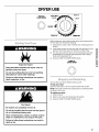
DRYER USE ................................................................................. 21
Starting Your Dryer .................................................................... 21
Stopping and Restarting ........................................................... 21
Loading ...................................................................................... 22
Drying, Cycle and Temperature Tips ........................................ 22
Cycles ........................................................................................ 22
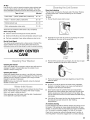
LAUNDRY CENTER CARE ......................................................... 23
Cleaning Your Washer ............................................................... 23
Water inlet Hoses ...................................................................... 23
Cleaning the Lint Screen ........................................................... 23
Cleaning the Dryer interior........................................................ 24
Removing Accumulated Lint ..................................................... 24
Vacation, Storage, and Moving Care ........................................ 24
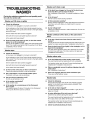
TROUBLESHOOTING WASHER ................................................ 25
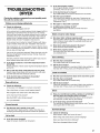
TROUBLESHOOTING DRYER .................................................... 27
2

WE SERVICE
WHAT WE SELL
Your purchase has added value because you can depend on
Sears HomeCentral ®for service. With over 12,000 trained repair
specialists and access to over 4.2 million parts and accessories,
we have the tools, parts, knowledge and skills to ensure our
pledge: We Service What We Sell.
Sears Maintenance Agreements
Your Kenmore ®appliance is designed, manufactured and tested
to provide years of dependable operation. Yet any major
appliance may require service from time to time. The Sears
Maintenance Agreement offers you an outstanding service
program, affordably priced.
The Sears Maintenance Agreement
• Is your way to buy tomorrow's service at today's price.
• Eliminates repair bills resulting from normal wear and tear.
• Provides for non-technical and instructional assistance.
• Even if you don't need repairs, provides an annual Preventive
Maintenance Check, at your request, to ensure that your
appliance is in proper running condition.
Some limitations apply. For more information, call
1-800-827-6655.
WARRANTY
Full One-Year Warranty on Mechanical and Eleckical Parts
For one year from the date of purchase, when this laundry center
is installed and operated according to the instructions provided in
this Use and Care Guide, Sears will repair this laundry center, free
of charge, if defective in material or workmanship.
NOTE: Exhausting your laundry center with a plastic vent can
void this warranty. See "Installation Instructions" for the complete
exhaust requirements for this laundry center.
Limited Five-Year Warranty on Gearcase Parts
For the second through fifth years from the date of purchase,
Sears will replace any gearcase parts that are defective in
material or workmanship. You will be charged for labor after the
first year.
Limited Ten-Year Warranty on Plastic Tub
For the second through tenth years from the date of purchase,
Sears will replace the plastic tub if defective in material or
workmanship. You will be charged for labor after the first year.
Warranty Restriction
If the laundry center is subject to other than private family use,
the above warranty coverage is effective for only 90 days.
Warranty Service
Warranty service is available by contacting the nearest Sears
Service Center. This warranty applies only while the product is in
use in the United States.
This warranty gives you specific legal rights and you may also
have other rights which vary from state to state.
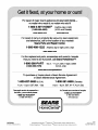
For Sears warranty information or to contact a Sears Service
Center, please reference the service numbers located on the
back page of this manual.
Sears, Roebuck and Co.
D/817WA, Hoffman Estates, IL 60179
Product Record
In the space below, record your complete model number, serial
number, and purchase date. You can find this information on the
model and serial number label, located at the top inside dryer
door well.
Have this information available to help you quickly obtain
assistance or service when you contact Sears concerning your
appliance.
Model number
Serial number
Purchase date
Save these instructions and your sales receipt for future
reference.

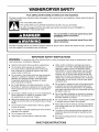
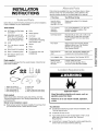
WASHER/DRYER SAFETY
Your safety and the safety of others are very important.
We have provided many important safety messages in this manual and on your appliance. Always read and obey all
safety messages.
This is the safety alert symbol.
This symbol alerts you to potential hazards that can kill or hurt you and others.
All safety messages will follow the safety alert symbol and either the word "DANGER" or
"WARNING." These words mean:
You can be killed or seriously injured if you don't
immediately follow instructions.
You can be killed or seriously injured if you don't
follow instructions.
All safety messages will tell you what the potential hazard is, tell you how to reduce the chance of injury, and tell you
what can happen if the instructions are not followed.
IM PORTANT SAFETY INSTRUCTIONS
WARNING: To reduce the risk of fire, electric shock, or injury to persons when using the washer/dryer, follow
basic precautions, including the following:
Read all instructions before using the washer/dryer.
Do not place items exposed to cooking oils in
your dryer. Items contaminated with cooking oils
may contribute to a chemical reaction that could
cause a load to catch fire.
Do not wash or dry articles that have been previously
cleaned in, washed in, soaked in, or spotted with
gasoline, dry-cleaning solvents, other flammable,
or explosive substances as they give off vapors
that could ignite or explode.
• Do not add gasoline, dry-cleaning solvents, or other
flammable, or explosive substances to the wash water.
These substances give off vapors that could ignite or
explode.
• Do not allow children to play on or in the washer/dryer. •
Close supervision of children is necessary when
the washer/dryer is used near children.
• Before the washer/dryer is removed from service or dis- •
carded, remove the doors to the washer/dryer compart-
ments.
• Do not reach into the washer/dryer if the tub, agitator
or drum is moving.
• Do not install or store the washer/dryer where it will be
exposed to the weather.
• Do not tamper with controls.
• Clean dryer lint screen before or after each load.
Under certain conditions, hydrogen gas may be
produced in a hot water system that has not been
used for 2 weeks or more. HYDROGEN GAS IS
EXPLOSIVE. If the hot water system has not been
used for such a period, before using the washing
machine, turn on all hot water faucets and let the
water flow from each for several minutes. This will
release any accumulated hydrogen gas. As the gas
is flammable, do not smoke or use an open flame
during this time.
Do not repair or replace any part of the washer/dryer
or attempt any servicing unless specifically recom-
mended in this Use and Care Guide or in published
user-repair instructions that you understand and have
the skills to carry out.
Do not use fabric softeners or products to eliminate
static unless recommended by the manufacturer of
the fabric softener or product.
Do not use heat to dry articles containing foam rubber
or similarly textured rubber-like materials.
Keep area around the exhaust opening and adjacent
surrounding areas free from the accumulation of lint,
dust, and dirt.
• The interior of the machine and dryer exhaust vent
should be cleaned periodically by qualified service
personnel.
• See "Electrical Requirements" section for grounding
instructions.
SAVETHESEINSTRUCTIONS
4

INSTALLATION
INSTRUCTIONS
Check that you have everything necessary for correct installation.
Proper installation is your responsibility.
Tools needed:
• #2 Phillips and flat-blade • Knife
screwdriver
• Safety glasses
• Adjustable wrench that
opens to 1 in. (2.5 cm) or • Duct tape
%6 in. open-end wrench • Caulking gun and
(for adjusting dryer feet) compound (for installing
• Level new exhaust vent)
• % in. nut driver or socket • Gloves
wrench • Pliers
• Wood block(for leveling) • Scissors
• Ruler or measuring tape • Tin snips (for new vent
• Wire stripper (direct wire installations)
installations)
Parts supplied
Remove parts package from the washer basket. Check that all
parts were included.
Parts listed are available from your local Sears store or Sears
Service Center. For more information, please reference the
service numbers located on the back page of this manual.
If You Have You Will Need to Buy
Laundry tub or Sump pump system (if not already
standpipe taller available)
than 96 in. (2.4 m)
1 in. (2.5 cm) 2 in. (5 cm) diameter to 1 in. (2.5 cm)
diameter diameter standpipe adapter, Part
standpipe Number 3363920
Overhead sewer Standard 20 gal. (76 L) 34 in. (86.4 cm)
tall drain tub or utility sink and sump
pump (available from local plumbing
suppliers)
Floor drain Siphon break, Part Number 285320,
additional drain hose, Part Number
285702 and connector kit,
Part Number 285442
Drain hose too Drain hose, Part Number 285664 and
short connector kit, Part Number 285442
Lint clogged drain Drain protector, Part Number 367031
Water faucets 2 longer water fill hoses:
beyond reach of 6 ft (1.8 m) Part Number 76314,
fill hoses 10 ft (3.0 m) Part Number 350008
tL,}0St ©_'1_,@(;_,, Y@'_SX?Yl1:,S
5 6 7
1. Water inlet hoses (2)
2. Intet hose flat washers (4)
3. Rear leveling legs (2)
4. Front leveling legs (2)
5. Plastic strap
6. Drain hose
7. Yellow, single wire hose clamp
8. Silver, double-wire hose clamp
Parts needed:
Check local codes, electrical supply and venting, and read
"Electrical Requirements" and "Venting Requirements" before
purchasing parts.
Mobile home installations require:
• Metal exhaust system hardware available for purchase from
your local Sears store or Sears Service Center.
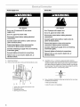
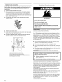
Explosion Hazard
Keep flammable materials and vapors, such as
gasoline, away from dryer.
Failure to do so can result in death, explosion,
or fire.
You will need
• A location that allows for proper exhaust installation. See
"Venting Requirements."
• A separate 30 amp circuit.
• A grounded electrical outlet located within 2 ft (61 cm) of
either side of the laundry center. See "Electrical
Requirements."
• A sturdy floor to support the laundry center weight (laundry
center, water and load) of 500 Ibs (226.8 kg).

Alevelfloorwithamaximumslopeof1in.(2.5cm)under
entire laundry center. Clothes may not tumble properly and
automatic sensor cycles may not operate correctly if dryer is
not level. Installing on carpet is not recommended.
A water heater set to deliver 120°F (49°C) water to the
washer.
• Hot and cold water faucets located within 4 f1 (1.2 m) of the
hot and cold water fill valves, and water pressure of 5-100 psi
(34.5-689.6 kPa).
Install the laundry center where it is protected from water and/or
weather.
Do not operate your washer in temperatures at or below 32°F
(O°C). Some water can remain in the washer and can cause
damage in low temperatures. See "Vacation, Storage, and
Moving Care" for winterizing information.
Do not operate your dryer at temperatures below 45°F (7°C). At
lower temperatures, the dryer might not shut off at the end of an
automatic cycle. This can result in longer drying times.
Check code requirements. Some codes limit, or do not permit,
installation of the laundry center in garages, closets, mobile
homes, or sleeping quarters. Contact your local building
inspector.
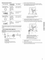
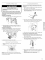
Installation Clearances
The location must be large enough to fully open the dryer door.
Laundry Center Dimensions
• Rear clearance may be 0 in. when house exhaust system is
lined up directly with dryer exhaust.
ooo oo
o'_-l-_'h'_-l._o'_ i'I_,'_
Io=I)(Im,_) loc_ ll.!i_)llm.21_)
7 2
48,=
3'_.ec_
_4=,,)
1, Recessed Area
2. Side view - closet or confined area
3. Closet door with vents
Mobile Home-Additional Installation Requirements
This laundry center is suitable for mobile home installations.
The installation must conform to the Manufactured Home
Construction and Safety Standard, Title 24 CFR, Part 3280
(formerly the Federal Standard for Mobile Home Construction
and Safety, Title 24, HUD Part 280).
Mobile home installations require:
• Metal exhaust system hardware which is available for
purchase from your local Sears store or Sears Service Center.
Special provisions must be made in mobile homes to
introduce outside air into the dryer. The opening (such as a
nearby window) should be at least twice as large as the dryer
exhaust opening.
*Most installations require a minimum 51_ in. (14 cm) clearance
behind the dryer for the exhaust vent with elbow. See "Venting
Requirements."
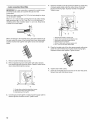
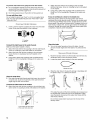
The laundry center can be installed using the standpipe drain
system (floor or wall), the laundry tub drain system, or the floor
drain system. Select the drain hose installation method you need
(see "Alternate Parts").
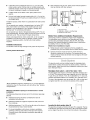
Standpipe drain system - wall or floor (view I & 2)
The standpipe drain requires a minimum diameter standpipe of 2
in. (5 cm). The minimum carry-away capacity can be no less than
17 gal. (64 L) per minute. A 2 in. (5 cm) diameter to 1 in. (2.5 cm)
diameter standpipe adapter kit is available. See "Alternate Parts."
The top of the standpipe must be at least 39 in. (99 cm) high and
no higher than 96 in. (2.4 m) from the bottom of the washer.
Minimum installation spacing for recessed area or closet
installation
The following dimensions shown are for the minimum spacings
allowed.
• Additional spacing should be considered for ease of
installation and servicing.
Additional clearances might be required for wall, door and
floor moldings.
Additional spacing of 1 in. (2.5 cm) on all sides of the dryer is
recommended to reduce noise transfer.
For closet installation, with a door, minimum ventilation
openings in the top and bottom of the door are required.
Louvered doors with equivalent ventilation openings are
acceptable.
1 2
Laundry tub drain system (view 3)
The laundry tub needs a minimum 26 gal. (76 L) capacity. The top
of the laundry tub must be at least 34 in. (86.4 cm) above the floor
and no higher than 96 in. (2.4 m) from the bottom of the washer.
6

Floor drain system (view 4)
The floor drain system requires a siphon break that may be
purchased separately. (See "Alternate Parts.")
The siphon break must be a minimum of 28 in. (71 cm) from the
bottom of the washer. Additional hoses might be needed.
3
4
It isyour responsibility
• Tocontact a qualified electrical installer.
• To be sure that the electrical connection is adequate and in
conformance with the National Electrical Code, ANSl/NFPA
70-latest edition and all local codes and ordinances.
A copy of the above code standards can be obtained from:
National Fire Protection Association, Batterymarch Park,
Quincy, MA 02269.
• To supply the required 3 or 4 wire, single phase, 120/240-volt,
60-Hz., AC-only electrical supply (or 3 or 4wire, 120/208-volt
electrical supply, if specified on the serial/rating plate) on a
separate 30-ampere circuit, fused on both sides of the line. A
time-delay fuse or circuit breaker is recommended. Connect
to an individual branch circuit. Do not have a fuse in the
neutral or grounding circuit.
• Do not use an extension cord.
• If codes permit and a separate ground wire is used, it is
recommended that a qualified electrician determine that the
ground path is adequate.
Electrical Connection
To properly install your laundry center, you must determine the
type of electrical connection you will be using and follow the
instructions provided for it here.
• If local codes do not permit the connection of a cabinet
ground connector to the neutral wire, see "Optional 3-wire
Connection."
• This laundry center is manufactured with a 3-wire, cabinet-
ground conductor connected to the NEUTRAL (white or
center wire) of the wiring harness at the terminal block.
• Use a 4-wire conductor cord when the laundry center is
installed in a mobile home or an area where local codes do
not permit grounding through the neutral.
If using a power supply cord:
Dryer power supply cord must be:
• UL-listed
• Rated 120/240 volt minimum
• 30 amp
• Type SRD or SRDT
• At least 5 ft (1.52 m) long
The wires that connect to the dryer must end in ring terminals or
spade terminals with upturned ends.
If your outlet looks like this:
©
4-wire receptacle (14-30R)
Then choose a 4-wire power supply cord with ring or spade
terminals and UL approved strain relief. The 4-wire power supply
cord must have 4, 10 gauge solid copper wires and match a 4-
wire receptacle of NEMA Type 14-30R. The ground wire (ground
conductor) may be either green or bare. The neutral conductor
must be identified by a white cover.
If your outlet looks like this:
©
3-wire receptacle (10-30R)
Then choose a 3-wire power supply cord with ring or spade
terminals and UL approved strain relief. The 3-wire power supply
cord, must have 3, No.-10 copper wires and match a 3-wire
receptacle of NEMA Type 10-30R.
If connecting by direct wire:
Power supply cable must match power supply (4-wire or 3-wire)
and be:
• Flexible armored or non-metallic sheathed copper cable (with
ground wire). All current-carrying wires must be insulated.
• 10 gauge solid copper wire (Do not use aluminum.)
• At least 5 ft (1.52 m) long.
GROUNDING INSTRUCTIONS
• For a grounded, cord-connected washer/dryer:
This washer/dryer must be grounded. In the event of malfunc-
tion or breakdown, grounding will reduce the risk of electric
shock by providing a path of least resistance for electric
current. This washer/dryer uses a cord having an equipment-
grounding conductor and a grounding plug. The plug must be
plugged into an appropriate outlet that is properly installed and
grounded in accordance with all local codes and ordinances.
• For a permanently connected washer/dryer:
This washer/dryer must be connected to a grounded metal,
permanent wiring system, or an equipment-grounding con-
ductor must be run with the circuit conductors and connected
to the equipment-grounding terminal or lead on the
washer/dryer.
WARNING: Improper connection of the equipment-
grounding conductor can result in a risk of electric shock.
Check with a qualified electrician or service representative or
personnel if you are in doubt as to whether the washer/dryer
is properly grounded. Do not modify the plug on the power
supply cord: if it will net fit the outlet, have a proper outlet in-
stalled by a qualified electrician.
SAVE THESE INSTRUCTIONS

PowerSupplyCord DirectWire
FireHazard
UseanewULapproved30amppower
supplycord.
UseaULapprovedstrainrelief.
Disconnectpowerbeforemakingelectrical
connections.
Connectneutralwire(whiteorcenterwire)to
centerterminal(silver).
Groundwire(greenorbarewire)mustbe
connectedtogreengroundconnector.
Connectremaining2supplywiresto remaining
2terminals(gold).
Securelytightenallelectricalconnections.
Failureto dosocanresultindeath,fire,or
electricalshock.
FireHazard
Use10gaugesolidcopperwire.
UseaULapprovedstrainrelief.
Disconnectpowerbeforemakingelectrical
connections.
Connectneutralwire(whiteorcenterwire)to
centerterminal(silver).
Groundwire(greenorbarewire)mustbe
connectedtogreengroundconnector.
Connectremaining2supplywiresto remaining
2terminals(gold).
Securelytightenallelectricalconnections.
Failureto dosocanresultindeath,fire,or
electricalshock.
1. Disconnect power.
2. Remove the hold-down screw and terminal block cover.
2
3
n n ,,
1. Center silver-colored terminal-block screw
2. Hold-down screw
3. Terminal block cover
4. External ground connector
3.
Assemble a ¾ in. (1.9 cm) UL approved strain relief (UL
marking on strain relief) into the hole below the terminal block
opening. Tighten strain relief screws just enough to hold the
two clamp sections together. Put power supply cord through
the strain relief, The strain relief should have a tight fit with the
dryer cabinet and be in a horizontal position.
4. Now complete installation following instructions for your type
of electrical connection:
4-wire (recommended)
3-wire (if 4-wire is not available)
8

Electrical Connection Options
If your home has: And you will be Go to Section
connecting to:
4-wire receptacle A UL listed, 4-wire connection:
(NEMA Type 14-30R) 120/240 volt Power supply cord
minimum, 30
amp., dryer
power supply
cord*
4-wire direct A fused 4-wire connection:
disconnect or Direct Wire
circuit breaker
box*
3-wire receptacle A UL listed,
(NEMA type 10-30R) 120/240 volt
minimum, 30
amp., dryer
power supply
cord*
3-wire connection:
Power supply cord
3-wire direct A fused 3-wire connection:
disconnect or Direct Wire
circuit breaker
box*
*If local codes do not permit the connection of a frame-grounding
conductor to the neutral wire, go to "Optional 3-wire Connection"
section.
4-wire connection: Power supply cord
IMPORTANT: A 4-wire connection is required for all mobile
homes and where local codes do not permit the use of 3-wire
connections.
2 6
\
5 7
1.4-wire receptacle (NEMA type 14-30R)
2. 4-prong plug
3. Ground prong
4. Neutral prong
5. Spade terminals with upturned ends
6. 3/4in. (!.9 cm) UL approved strain relief
7. Ring terminals
1. Remove center terminal block screw.
2. Remove appliance ground wire (green with yellow stripes)
from external ground connector screw. Fasten it under center,
silver colored terminal block screw.
/1
/
Z/
J
j'-- i€
1. Center silver-colored terminal block screw
2. Neutral grounding wire (green/yeilow)
3. External ground connector
3. Connect ground wire (green or bare) of power supply cord to
external ground conductor screw. Tighten screw.
4. Connect neutral wire (white or center wire) of power supply
cord under center screw of the terminal block. Tighten screw.
5 4
1. Neutral wire (white or center wire)
2. Center silver-colored terminal block screw
3. Neutral grounding wire (green/yellow)
4. Externa! ground connector
5. Green or bare wire of power supply cord
6. 3/4in. (1.9 cm) UL listed, strain relief
5. Connect the other wires to outer terminal block screws.
Tighten screws.
6. Tighten strain relief screws.
7. Insert tab of terminal block cover into slot of dryer rear panel.
Secure cover with hold-down screw.

4-wire connection: Direct Wire
IMPORTANT: A 4-wire connection is required for mobile homes
and where local codes do not permit the use of 3-wire
connections.
Direct wire cable must have 5 ft (1.52 m) of extra length so dryer
can be moved if needed.
Strip 5 in. (12.7 cm) of outer covering from end of cable, leaving
bare ground wire at 5 in. (12.7 cm). Cut 11/2in. (3.8 cm) from 3
remaining wires. Strip insulation back 1 in. (2.5 cm). Shape ends
of wires into a hook shape.
When connecting to the terminal block, place the hooked end of
the wire under the screw of the terminal block (hook facing right),
squeeze hooked end together and tighten screw. See example
below.
1. Remove center terminal block screw.
2. Remove appliance ground wire (green with yellow stripes)
from external ground connector screw. Fasten it under center,
silver colored terminal block screw.
/1
IOI Z/_
D _//
2-
4. Place the hooked end of the neutral wire (white or center wire)
of power supply cable under the center screw of terminal
block (hook facing right). Squeeze hooked end together.
Tighten screw.
2
1.Neutral wire
o
0 ,_/y
.............6 '5 4
"white or center wire)
2. Center silver-colored terminal block screw
3, Neutral grounding wire (green/yellow)
4, External ground connector
5. Green or bare wire of power supply cord
6. 3/4in. (1.9 cm) UL listed, strain relief
5. Place the hooked ends of the other power supply cable wires
under the outer terminal block screws (hooks facing right).
Squeeze hooked ends together. Tighten screws.
6. Tighten strain relief screws.
7. Insert tab of terminal block cover into slot of dryer rear panel.
Secure cover with hold-down screw.
1.Center silver-colored terminal block screw
2. Neutral grounding wire (green/yeilow)
3. External ground connector
3. Connect ground wire (green or bare) of power supply cable to
external ground conductor screw. Tighten screw.
10

__ When connecting to the terminal block, place the hooked end of
3-wire connection: Power supply cord the wire under the screw of the terminal block (hook facing right),
squeeze hooked end together and tighten screw. See example
Use where local codes permit connecting cabinet-ground
conductor to neutral wire.
below.
24
; /
3 7 6
1.3-wire receptacle (NEMA type 10-3OR)
2. 3-wire plug
3. Neutralprong
4. Spade terminalswith up turned ends
5. 3/4in. (!.9 cm) UL approved strain relief
6. Ring terminals
7.Neutral (white or center wire)
1. Loosen or remove center terminal block screw.
2. Connect neutral wire (white or center wire) of power supply
cord to the center, silver colored terminal screw of the
terminal block. Tighten screw.
2
1 -,,.,,%,
.........
"',,.,,4
1. Neutral wire (white or center wire)
2. Center sitver-cotored terminal block screw
3. Neutral grounding wire (green/yellow)
4. External ground connector
5. 3/4in. (!.9 cm) UL listed, strain relief
1. Loosen or remove center terminal block screw.
2. Placethehookedendoftheneutralwire(whiteorcenterwire)
of power supply cable under the center screw of terminal
block (hook facing right). Squeeze hooked end together.
Tighten screw.
,2
1. Neutral wire (white or center wire)
2. Center silver-colored terminal block screw
3. Neutral grounding wire (green/yellow)
4. External ground connector
5. _/4in. (!.9 em) UL listed, strain relief
3. Place the hooked ends of the other power supply cable wires
under the outer terminal block screws (hooks facing right).
Squeeze hooked ends together. Tighten screws.
3. Connect the other wires to outer terminal block screws.
Tighten screws.
4. Tighten strain relief screws.
5. Insert tab of terminal block cover into slot of dryer rear panel.
Secure cover with hold-down screw.
3-wire connection: Direct Wire
Use where local codes permit connecting cabinet-ground
conductor to neutral wire.
Direct wire cable must have 5 ft (1.52 m) of extra length so dryer
can be moved if needed.
Strip 3V2in. (8.9 cm) of outer covering from end of cable. Strip
insulation back 1 in. (2.5 cm) If using 3-wire cable with ground
wire, cut bare wire even with outer covering. Shape ends of wires
into a hook shape.
4. Tighten strain relief screws.
5. Insert tab of terminal block cover into slot of dryer rear panel.
Secure cover with hold-down screw.
11

Optional 3-wire connection
Use for direct wire or power supply cord where local codes
do not permit connecting cabinet-ground conductor to
neutral wire.
1. Remove center terminal block screw.
2. Remove appliance ground wire (green with yellow stripes)
from external ground connector screw. Connect appliance
ground wire and the neutral wire (white or center wire) of
power supply cord/cable under center, silver colored terminal
block screw. Tighten screw.
3. Connect the other wires to outer terminal block screws.
Tighten screws.
4. Tighten strain relief screws.
5. Insert tab of terminal block cover into slot of dryer rear panel.
Secure cover with hold-down screw.
6. Connect a separate copper ground wire from the external
ground connector screw to an adequate ground.
o
1........... ¸¸¸¸¸¸¸¸2
1. Neutral wire (white or center wire)
2. Neutral grounding wire (green/yellow)
3. Grounding path determined by a quaflfied electrician
4. External ground connector
Fire Hazard
Use a heavy metal vent.
Do not use a plastic vent.
Do not use a metal foil vent.
Failure to follow these instructions can result in
death or fire.
WARNING: To reduce the risk of fire, this laundry center
MUST BE EXHAUSTED OUTDOORS.
4 in. (10.2 cm) heavy metal exhaust vent and clamps must be
used. DURASAFE TM venting products are recommended and are
available from your local Sears store or Sears Service Center.
DURASAFE TM vent products can be purchased from your dealer.
for further information, please reference the service number
located on the back page of this manual or visit our Internet site
at: www.sears.com.
• Do not exhaust the dryer into any gas vent, chimney, wall,
ceiling, or a concealed space of a building.
• Do not use an exhaust hood with a magnetic latch.
• Do not install flexible metal vent in enclosed walls, ceilings or
floors.
• Do not use screws or other fastening devices that extend into
the interior of the vent to secure vent.
IMPORTANT: Observe all governing codes and ordinances.
Improper venting can cause moisture and lint to collect
indoors, which may result in:
• Moisture damage to woodwork, furniture, paint, wall-
paper, carpets, etc.
• Housecleaning problems and health problems.
12
Use a heavy metal vent. Do not use plastic or metal foil vent.
Rigid metal vent is recommended to prevent crushing and kinking.
Flexible metal vent must be fully extended and supported when
the laundry center is in its final position. Remove excess flexible
metal vent to avoid sagging and kinking that may result in
reduced airflow.
An exhaust hood should cap the vent to prevent rodents and
insects from entering the home.
Exhaust hood must be at least 12 in. (30.5 cm) from the ground or
any object that may be in the path of the exhaust (such as
flowers, rocks or bushes, etc.).
If using an existing vent system, clean lint from the entire length
of the system and make sure exhaust hood is not plugged with
lint. Replace any plastic or metal foil vent with rigid metal or
flexible metal vent.
Use duct tape to seal all joints.

Toprotectthefloor,usealargeflatpieceofcardboardfromthe
shippingcarton.Gentlyplacethelaundrycenteronitsside,on
thecardboard.
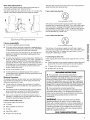
Install the rear leveling legs
1o Push legsintoholes in rear corners until they snap into place.
Proper connection of the drain hose protects your floors from
damage due to water leakage. Carefully read and follow these
instructions.
1o Wet the inside of the straight end of the drain hose with tap
water. Do not use any other lubricant.
2. Squeeze ears of the silver, double-wire clamp with pliers to
open. Place clamp over the straight end of the drain hose 1¼
in. (6.4 mm) from the end.
3. Open clamp. Twist hose back and forth while pushing onto
drain connector on the side of the laundry center. Continue
until hose contacts the ribbed stops on the cabinet.
2. Check adjustability of rear legs by pushing in one leg. The
other leg should come out. Check both legs. Ifthey do not
move freely, repeat step 1.
Install the front leveling legs
1. Examine the front leveling legs. Find the diamond marking.
2. Screw front legs by hand, into the holes in the triangular
braces in the front corners. Use wrench to finish turning the
legs until the diamond marking is no longer visible.
3. Carefully stand the laundry center upright.
1o Open the washer lid. The latch under the dryer will keep the
lid open.
2. Pull the foam packing ring out of the washer.
\
\
\
\
4o Place clamp over the area marked "CLAMR" Release clamp.
For laundry tub or standpipe drain systems
Connecting the drain hose "hook" to the corrugated drain hose:
1o Wet the outside end of the drain hose with tap water. Do not
use any other lubricant.
2. Twist and push the "hook" back and forth while pushing
down onto the drain hose. Continue until the "hook" is down
to the enlarged diameter of the drain hose.
NOTE: Keep the foam ring and use it when transporting your
laundry center. This packing material is used to keep the washer
tub stable during transport.
1, Hooked end
2. Drain hose
3. Open the yellow single-wire clamp and slide over the end of
the drain hose "hook" to secure the sections together (pliers
optional).
4. Put the hooked end of drain hose into laundry tub or
standpipe. Rotate "hook" to eliminate kinks.
13

To prevent drain water from going back into the washer:
• Do not straighten hooked end of the drain hose and force
excess drain hose into standpipe. Hose should be secure but
loose enough to provide a gap for air.
• Do not lay excess hose on the bottom of the laundry tub.
For use with floor drain
Do not install the drain hose "hook" on to the corrugated drain
hose. You may need additional parts (see "Floor Drain" under
"Alternate Paris').
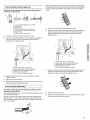
1o Insert a new flat washer (supplied) into each end of the inlet
hoses. Firmly seat the washers in the couplings.
1 2
1, Coupling
2. Washer
Connect the inlet hoses to the water faucets
Make sure the washer basket is empty.
2. Attach the hose with the red coupling to the hot water faucet.
Screw on coupling by hand until seated on the washer.
3. Attach the hose with the blue coupling to the cold water
faucet. Screw on coupling by hand until seated on the
washer.
4. Using pliers, tighten the couplings with an additional two-
thirds turn. Do not overtighten. Damage to the valves can
result.
Clear the water lines
5. Run water through both faucets and inlet hoses, into a bucket
or laundry tub, to get rid of particles in the water lines that
might clog the inlet valve screens.
Connect the inlet hoses to the washer
6. Attach the hose with the blue coupling to the cold (top) inlet
valve. Screw on coupling by hand until seated on the washer.
1. Cold water inlet valve (blue)
2. Hot water inlet valve (red)
7. Attach the hose with the red coupling to the hot water
(bottom) inlet valve. Screw on coupling by hand until seated
on the washer.
8. Using pliers, tighten the couplings with an additional two-
thirds turn. Do not overtighten. Damage to the valves can
result.
If you are working in a closet or recessed area
Move the laundry center into its final position and remove
cardboard from under laundry center. Remove the access panel
by removing two Phillips-head screws, located at the top of the
access panel. Set panel and screws aside. Complete hook-up of
water hoses, exhaust vent, and (on gas models) the flexible gas
connector through the access area. Replace access panel upon
completion of laundry center installation.
Check for leaks
9. Turn on the water faucets and check for leaks. A small
amount of water might enter the washer. You will drain this
later.
1. Move the laundry center to its final location and remove any
cardboard used to move the laundry center.
2. Locate the plastic strap included in the parts package.
Beaded tie strap
3. Wrap the drain hose to the laundry tub leg or standpipe with
the plastic strap (1 or 2 below) and secure.
k
1 2 3
Ifthe water faucets and the drain standpipe are recessed, put
the hooked end of the drain hose in the standpipe. Tightly
wrap the plastic strap around the water inlet hoses and the
drain hose (3 above).
Do not force excess drain hose back into the rear of the
laundry centen
14

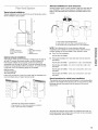
Typical exhaust installations
Typical installations vent the dryer from rear of the laundry center.
Other installations are possible.
Altemate installations for close clearances
Venting systems come in many varieties. Select the type best for
your installation. Three close-clearance installations are shown.
Refer to the manufacturer's instructions provided with the vent
system.
1 Im '
2 I.q '7
1, Dryer 5. Elbow
2. Heavy metal vent 6. Duct tape & clamps
3. Duct tape & clamps 7. Elbow
4. Wall 8. Exhaust hood
Optional exhaust installations
This laundry center can be converted to exhaust out the right or
left side. To convert the laundry center, use Side Exhaust Kit
Part Number 279823. If your laundry center was previously
exhausted from the right or left side, it can be converted to rear
exhaust by using standard offset connections. To cover the hole
in the side, one of the following plugs can be added:
692790 (white)
3979370 (graphite)
3977784 (biscuit)
Follow the instructions in the kit to install. Kits are available from
your local Sears store or Sears Service Center.
1. Loop system with standard elbows
2. Loop system with one offset & one standard elbow
3. Vent system with one periscope [2 in. (5 cm) clearance]
NOTE: The following kits for close clearance alternate
installations are available for purchase. Please see the service
number located on the back page of this manual to order.
• Over-The-Top Installation:
Part Number 26-49909
Periscope Installation (For use with dryer vent to wall vent
mismatch):
Part Number 26-49901 - Less than 5 in. (12.7 cm) mismatch
Part Number 26-49908 - 5 in. (12.7 cm) to 18 in. (45.7 cm)
mismatch
Part Number 26-49904 - 18 in. (45.7 cm) to 29 in. (73.7 cm)
mismatch
Part Number 26-49905 - 29 in. (73.7 cm) to 50 in. (127 cm)
mismatch
Special provisions for mobile home installations
The exhaust vent must be securely fastened to a noncombustible
portion of the mobile home structure. Do not use screws or other
fastening devices that extend into the interior of the vent to
secure vent.
1. Standard rear offset exhaust installation
2. Rear exhaust for offset close clearance connection
3. Left or right side exhaust installation
Terminate the exhaust vent outside. The exhaust vent must not
terminate beneath the mobile home and must not be connected
to any other duct, vent or chimney.
15

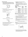
Determine Vent Length
1. Select the route that will provide the straightest and most
direct path outdoors. Plan the installation to use the fewest
number of elbows and turns. When using elbows or making
turns, allow as much room as possible. Bend vent gradually
to avoid kinking. Avoid 96° turns.
bs_er good
?J
2. Determine vent length.
The maximum length of the exhaust system depends upon:
• The type of vent (rigid metal or flexible metal).
• The number of elbows used.
• Type of hood.
Recommended hood styles are shown here.
1
(10.2 cm)
1, Louvered hood style
2. Box hood style
The angled hood style (shown following) is acceptable.
2.5"
See the exhaust vent length chart that matches your hood
type for the maximum vent lengths you can use.
Exhaust systems longer than specified will:
• Shorten the life of the dryer.
• Reduce performance, resulting in longer drying times and
increased energy usage.
3. Determine the number of elbows you will need.
IMPORTANT: Do not use vent runs longer than those
specified in the Vent Length Chart.
The chart below helps you determine your maximum vent
length based on the number of 90 ° turns or elbows you will
need and the type of vent (rigid or flexible metal) and hood
that you will use.
Vent Length Chart
Number of Type of Vent Box or Angled
90° turns Louvered hoods
or elbows hoods
0 Rigid metal 34 ft (12.2 m) 29 ft (10,7 m)
Flexible metal 21 ft (7.6 m) 16 ft (6.1 m)
1 Rigid metal 24 ft (9.7 m) 20 ft (8.2 m)
Flexible metal 15 ft (6.4 m) 10 ft (4.9 m)
2 Rigid metal 14 ft (7.3 m) 12 ft (5.8 m)
Flexible metal 7 ft (4.6 m) 2 ft (3.0 m)
NOTE: Side exhaust adds a 90° turn inside the laundry center. To
determine maximum exhaust length, add 1 90° turn to the chart.
1. (Optional) Put on safety glasses and gloves.
2. Install exhaust hood. Use caulking compound to seal exterior
wall opening around exhaust hood.
3. Connect vent to exhaust hood. Vent must fit inside exhaust
hood. Secure vent to exhaust hood with 4 in. (16.2 cm)
clamp.
4. Run vent to dryer location. Use the straightest path possible
(see "Determine Vent Length"). Avoid 90° turns. Use duct
tape to seal all joints.
Properly leveling your laundry center prevents excessive noise
and vibration.
1o Check the levelness of the laundry center by placing a level
on the top edge of the washer, first side-to-side, then front-
to-back.
2. If the laundry center is not level, prop up the front with a
wood block and adjust the feet up or down as necessary.
Remove wood block and lower laundry center. Repeat this
step until the laundry center is level.
16

1. Using a 4 in. (10.2 cm) clamp, connect vent to exhaust outlet
in laundry center. If connecting to existing vent, make sure
the vent is clean. The vent must fit over the exhaust outlet
and inside the exhaust hood. Make sure the vent is secured
to exhaust hood with a 4 in. (10.2 cm) clamp.
2. Move laundry center into final position. Do not crush or kink
vent. Make sure laundry center is level.
1. Check to be sure all parts are now installed. If there is an
extra part, go back through the steps to see which step was
skipped.
2. Check to be sure you have all of your tools.
3. Dispose/recycle all packaging materials. Keep the plastic
foam for use if the laundry center should be transported.
4. Check the laundry center's final location. Be sure the vent is
not crushed or kinked.
5. Check to be sure the laundry center is level and front leveling
feet are tight. See "Level Laundry Center."
6. Plug into a grounded outlet. Turn power on.
7. Check to be sure the water faucets are on.
8. Check for leaks around faucets and inlet hoses.
9. Remove the blue protective film on the console and any tape
remaining on the laundry center.
10. Read "Washer Use" and "Dryer Use."
11. Wipe the dryer drum interior thoroughly with a damp cloth to
remove any dust.
12. To test the washer, measure 1/2the normal recommended
amount of detergent and pour it into the washer. Close the lid.
Select HEAVY DUll/and pull out the Cycle Control knob.
Allow the washer to complete one whole cycle.
13. To test the dryer, set the dryer on a full heat cycle (not an air
cycle) for 20 minutes and start the dryer.
If the dryer will not start, check the following:
• Controls are set in a running or "On" position.
• Start button has been firmly pushed.
• Laundry Center is plugged into a grounded outlet.
• Electrical supply is connected.
• House fuse is intact and tight; or circuit breaker has not
tripped.
• Dryer door is closed.
14. When the dryer has been running for 5 minutes, open the
dryer door and feel for heat.
If you do not feel heat, turn the dryer off and check the
following:
• There may be 2 fuses or circuit breakers for the dryer.
Check to make sure both fuses are intact and tight, or
that both circuit breakers have not tripped. If there is still
no heat, contact a qualified technician.
NOTE: You may notice a burning odor when dryer is first heated.
This odor is common when the heating element is first used. The
odor will go away.
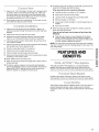
FEATURES AND
BENEFITS
The DUAL-ACTION TM Plus Agitator is a uniquely designed
agitator that helps push clothes that are on top down to the
bottom of the washer where the best cleaning action takes place.
_11)I_1%06;_11slII') "" I'] ° I "I"
= ,_....,.=<;== _JIISII llS:o Ie,
Durable finish resists scratching, staining and odors for long-
lasting quality. Fabrics are protected by the smooth wash basket.
This laundry center features 4 different ways to vent your dryer. A
properly exhausted laundry center will give you the shortest
drying time, lower your utility bill and extend the life of the laundry
center.
17

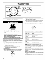
WASHER USE
_N 10 REGULAR
HEAVYDUTY -=eEN_ WA_ER "I_MP WATER LEVEL
nINSE PERMANENT umuu
PRESS wx_ wM. u_
IllllUl_110 SMN
SUPB112
KNIT/DELICATE
PREWASH RINSE
SOAK
Fire Hazard
Never place items in the washer that are
dampened with gasoline or other flammable
fluids.
No washer can completely remove oil.
Do not dry anything that has ever had any type of
oil on it (including cooking oils).
Doing so can result in death, explosion, or fire.
The following is a guide to starting your washer. Periodic
references to other sections of this manual provide more detailed
information.
1. Pour measured powdered or liquid detergent into the washer.
If desired, add powdered or liquid color safe bleach.
2. Place a load of sorted clothes in the washer.
• Load evenly to maintain washer balance. Mix large and
small items. See "Loading."
• Items should move easily through the wash water.
Overloading can cause poor cleaning.
3. Close the washer lid.
4. Turn the WATER LEVEL selector knob to the correct setting
for your wash load and the type of fabric being washed.
WATER LEVEL
• Choose a load size that allows the load to move freely for
best fabric care. See "Loading."
• You may change the load size selection after the washer
has started filling by turning the selector to a different
setting.
5. Set the WATER TEMP selector to the correct setting for the
type of fabric and soils being washed.
WA_ER _£MP
ct_ !
i
6.
Use the warmest water safe for the fabric. Follow garment
label instructions.
Water Temp Use For
Hot
111°F (44°C) Whites and pastels
or above Heavy soils
Warm
90°- 110°F Bright colors
(32°- 43°C) Moderate to light soils
Cold
70°- 9O°F Colors that bleed or fade
(21°- 32°C) Light soils
NOTE: In wash water temperatures colder than 70°F
(21°C), detergents do not dissolve well. Soils can be difficult
to remove. Some fabrics can retain wear wrinkles and have
increased pilling (the formation of small lint-like balls on the
surface of garments).
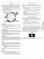
Push in the Cycle Control knob and turn it clockwise to the
wash cycle you want. Pull out the Cycle Control knob to start
the washer.
To stop or restart your washer:
• To stop the washer at any time, push in the Cycle Control
knob.
• To restart the washer, close the lid (if open) and pull out
the Cycle Control knob.
18

This section describes the available wash cycles and will help
you make the best cycle selections for your wash loads. Each
cycle is designed for different types of fabric and soil levels.
• The washer pauses briefly throughout each cycle. These
pauses are normal. Refer to "Normal Sounds" for sounds you
may hear during a wash cycle.
• Refer to "Understanding Washer Cycles" to learn what
happens during a wash cycle.
HEAVY DUTY
RINSE
PERMANENT
PRESS
When using extra detergent for heavily soiled clothes, or washing
special-care items, you may find an extra rinse and spin is
needed.
1. Push in the Cycle Control knob and turn it clockwise to any of
the RINSE settings.
• For fast agitation and spin, use the Heavy Duty cycle.
• For slow agitation and spin, use the Permanent Press
cycle.
2. Set the WATER LEVEL and WATER TEMP controls to the
desired setting.
3. Pull out the Cycle Control knob. The washer fills to the
selected load size, agitates, drains, and spins.
SHOIT |
P_IUUW 10
SLIPEII12
KNIT/DELICATE
PREWASH ,INSe
SOAK
Heavy Duty
Use this cycle for sturdy or heavily soiled loads. Wash combines
fast speed agitation and fast spin speeds.
• Use the Super or Regular settings for heavily soiled and
sturdy fabrics.
• Use the Short setting for light soil and delicate fabrics.
Permanent Press
The Permanent Press Cycle includes a load cooling process that
reduces wrinkling. Wash combines fast and slow speed agitation
and slow spin speeds.
When the timer reaches Pause, the washer will drain and pause
for approximately 2 minutes while some of the wash water is
drained and replaced with rinse water.
Knit/Delicate
Use this cycle for lingerie and loosely knit items. Partway through
the cycle the washer pauses and soaks the load for more gentle
care of lightly soiled delicate items. Wash combines slow speed
agitation for gentle soil removal and slow spin speeds to reduce
wrinkling.
Soak
The Soak cycle features 4 minutes of agitation followed by an
unlimited soak time to help remove heavy soils and stains that
need pretreatment. You will need to reset the washer to a SPIN
setting to remove water.
• The Soak cycle should be followed by the Heavy Duty or
Permanent Press or Prewash cycle with additional
detergent.
NOTE: Hot water is not recommended for soaking. It may set
some stains.
Prewash
Use this cycle to get up to 4 minutes of agitation to help remove
heavy soils and stains that need pretreatment
• The Prewash cycle should be followed by the Heavy Duty
or Permanent Press cycle with additional detergent.
A drain and spin may help shorten drying times for some heavy
fabrics or special-care items by removing excess water.
1. Push in the Cycle Control knob and turn it clockwise to any of
the SPIN settings.
• For a fast spin, use the Heavy Duty cycle.
• For a slow spin, use the Permanent Press cycle.
2. Pull out the Cycle Control knob. The washer drains, then
spins.
When the Cycle Control knob is set to a number and pulled out,
the washer fills (to the selected load size) before agitation and
timing start. The washer begins agitating immediately after filling;
agitation occurs with the washer lid up or down.
During agitation, the agitator creates a continuous rollover action
that provides a thorough cleaning of the wash load.
After agitation starts, the Cycle Control knob turns clockwise until
it points to an Off area and the cycle ends.
19

NOTE: The washer pauses briefly throughout each cycle. These
pauses are normal for washer operation.
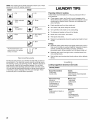
WASH RINSE
1. Fill _ 1. Fill
2. Wash selected _ 2. Rinse
time
_ 3. Drain* ._ 3. Drain
No agitation No agitation
_ 4. Spin _ 4. Spin-Spray
rinse
_ 5. Spin
qhe Permanent Presscycle I rq I 6. Off
partially drains, fills, agitates
briefly,and drains.
As with any new product, you will hear sounds that you are not
accustomed to. You may hear various sounds occurring during
the washing, rinsing, and spinning process. Between changes in
wash actions, there will be momentary pauses. You will hear
water spraying and splashing during the wash and rinse cycles.
You may hear air being pulled through the pump during the end
of draining or gears changing when the cycle changes. These
sounds are part of normal washer operation.
LAUNDRY TIPS
Preparing clothes for washing
Follow these recommendations to help you prolong the life of
your garments.
• Close zippers, snaps, and hooks to avoid snagging other
items. Remove pins, buckles, and other hard objects to avoid
scratching the washer interior. Remove non-washable trim
and ornaments.
• Empty pockets and turn them inside out.
• Turn down cuffs, brush away lint and dirt.
• Turn synthetic knits inside out to avoid pilling.
• Tie strings and sashes so they will not tangle.
• Mend tears, loose hems, and seams.
• Treat spots and stains.
• Stained or wet garments should be washed promptly for best
results.
Sorting
• Separate heavily soiled items from lightly soiled ones, even if
they would normally be washed together. Separate lint givers
(towels, chenille) from lint takers (corduroy, synthetics,
permanent press). When possible, turn lint givers inside out.
• Separate dark colors from light colors, colorfast items from
non-colorfast items.
• Sort by fabric and construction (sturdy cottons, knits, delicate
items).
Loading suggestions (maximum size loads)
Laundry Center
Heavy Work Clothes Towels
2 pair pants 9 bath towels or
3 work shirts 6 bath towels, 3 hand towels &
6 wash cloths
Permanent Press Mixed Load
6 shirts or 1 pair pants
2 double sheets & 2 pillowcases
2 pillowcases or 2 shirts
2 single sheets & 1 T-shirt
2 pillowcases
Knits Delioates
2 pair pants & 2 shirts or 1 camisole
3 dresses 2 slips
4 undergarments
1 set of sleepwear
1 half slip
20
Page is loading ...
Page is loading ...
Page is loading ...
Page is loading ...
Page is loading ...
Page is loading ...
Page is loading ...
Page is loading ...
-
 1
1
-
 2
2
-
 3
3
-
 4
4
-
 5
5
-
 6
6
-
 7
7
-
 8
8
-
 9
9
-
 10
10
-
 11
11
-
 12
12
-
 13
13
-
 14
14
-
 15
15
-
 16
16
-
 17
17
-
 18
18
-
 19
19
-
 20
20
-
 21
21
-
 22
22
-
 23
23
-
 24
24
-
 25
25
-
 26
26
-
 27
27
-
 28
28


Kenmore 11080754001 User manual
- Category
- Washing machines
- Type
- User manual
Ask a question and I''ll find the answer in the document
Finding information in a document is now easier with AI
Related papers
-
Kenmore 11063942101 Owner's manual
-
 Kenmore Elite Kenmore 27-1nch Wide - Extra Large Capacity Plus LAUNDRY CENTER Washer - Electric Dryer Owner's manual
-
-
-
 Kenmore Elite 110.6706 User manual
-
 Kenmore Elite 110.6706 User manual
-
-
-
 Kenmore Elite 11062082101 Owner's manual
-
Sears 11062622100 Owner's manual


Other documents
-
 Kenmore Elite 11024942301 Owner's manual
-
Whirlpool YLTE5243DQ5 Installation guide
-
-
-
-
Haier HLPW028AXW Installation and User Manual
-
-
 Kenmore Elite 11027152600 Owner's manual
-
Crosley CEDC392PQ1 Owner's manual
-

