Page is loading ...

TMS320C6457 DSP
Turbo-Decoder Coprocessor 2 (TCP2)
User's Guide
Literature Number: SPRUGK1
March 2009


Contents
Preface ........................................................................................................................................ 8
1 Features .............................................................................................................................. 9
2 Introduction ....................................................................................................................... 10
3 Overview ........................................................................................................................... 11
4 Standalone (SA) Mode ........................................................................................................ 12
4.1 Input Data Format ....................................................................................................... 13
4.2 Output Decision Data Format .......................................................................................... 16
4.3 Stopping Criteria ......................................................................................................... 16
4.4 Stopping Test Unit ....................................................................................................... 17
5 Shared-Processing (SP) Mode ............................................................................................. 18
5.1 Input Data Format ....................................................................................................... 22
5.2 Output Data Format ..................................................................................................... 24
6 Registers ........................................................................................................................... 25
6.1 Peripheral Identification Register (PID) ............................................................................... 27
6.2 TCP2 Input Configuration Register 0 (TCPIC0) ..................................................................... 28
6.3 TCP2 Input Configuration Register 1 (TCPIC1) ..................................................................... 29
6.4 TCP2 Input Configuration Register 2 (TCPIC2) ..................................................................... 29
6.5 TCP2 Input Configuration Register 3 (TCPIC3) ..................................................................... 30
6.6 TCP2 Input Configuration Register 4 (TCPIC4) ..................................................................... 31
6.7 TCP2 Input Configuration Register 5 (TCPIC5) ..................................................................... 32
6.8 Tail Symbols .............................................................................................................. 32
6.9 TCP2 Input Configuration Register 6 (TCPIC6) ..................................................................... 33
6.10 TCP2 Input Configuration Register 7 (TCPIC7) ..................................................................... 34
6.11 TCP2 Input Configuration Register 8 (TCPIC8) ..................................................................... 35
6.12 TCP2 Input Configuration Register 9 (TCPIC9) ..................................................................... 36
6.13 TCP2 Input Configuration Register 10 (TCPIC10) .................................................................. 37
6.14 TCP2 Input Configuration Register 11 (TCPIC11) .................................................................. 37
6.15 TCP2 Input Configuration Register 12 (TCPIC12) .................................................................. 39
6.16 TCP2 Input Configuration Register 13 (TCPIC13) .................................................................. 39
6.17 TCP2 Input Configuration Register 14 (TCPIC14) .................................................................. 40
6.18 TCP2 Input Configuration Register 15 (TCPIC15) .................................................................. 41
6.19 TCP2 Output Parameter Register 0 (TCPOUT0).................................................................... 42
6.20 TCP2 Output Parameter Register 1 (TCPOUT1).................................................................... 42
6.21 TCP2 Output Parameter Register 2 (TCPOUT2).................................................................... 43
6.22 TCP2 Execution Register (TCPEXE) ................................................................................. 43
6.23 TCP2 Endian Register (TCPEND) .................................................................................... 44
6.24 TCP2 Error Register (TCPERR) ....................................................................................... 45
6.25 TCP2 Status Register (TCPSTAT) .................................................................................... 47
6.26 TCP2 Emulation Register (TCPEMU)................................................................................. 49
7 Endianness ........................................................................................................................ 50
7.1 Data Memory for Systematic ........................................................................................... 50
SPRUGK1 – March 2009 Table of Contents 3
Submit Documentation Feedback

www.ti.com
8 Architecture ....................................................................................................................... 59
8.1 Sub-block and Sliding Window Segmentation ....................................................................... 60
8.2 Subframe Segmentation (SP mode only) ............................................................................ 61
8.3 Reliability and Prolog Length Calculation ............................................................................ 62
8.4 Added Features .......................................................................................................... 63
9 Programming ..................................................................................................................... 64
9.1 EDMA3 Resources ...................................................................................................... 65
9.2 Programming Standalone (SA) Mode ................................................................................. 66
9.3 Programming Shared-Processing (SP) Mode ....................................................................... 70
10 Output Parameters ............................................................................................................. 74
11 Events Generation .............................................................................................................. 74
12 Debug Mode: Pause After Each Map ..................................................................................... 75
13 Errors and Status ............................................................................................................... 75
13.1 Errors ...................................................................................................................... 75
13.2 Status ..................................................................................................................... 77
Contents 4 SPRUGK1 – March 2009
Submit Documentation Feedback

www.ti.com
List of Figures
1 3GPP and IS2000 Turbo-Encoder Block Diagram ..................................................................... 10
2 3GPP and IS2000 Turbo-Decoder Block Diagram ..................................................................... 11
3 TCP2 Block Diagram ...................................................................................................... 12
4 Standalone (SA) Mode Block Diagram .................................................................................. 13
5 Systematic/Parity Data for Rates 1/2, 1/3, 1/4, 1/5, and 3/4 ......................................................... 14
6 EN = 1 (Little-Endian Mode) Rate = 1/2 ................................................................................. 14
7 EN = 0 (Big-Endian Mode) Rate = 1/2................................................................................... 14
8 EN = 1 (Little-Endian Mode) Rate = 1/3 ................................................................................. 14
9 EN = 0 (Big-Endian Mode) Rate = 1/3................................................................................... 14
10 EN = 1 (Little-Endian Mode) Rate = 1/4 ................................................................................. 14
11 EN = 0 (Big-Endian Mode) Rate = 1/4................................................................................... 15
12 EN = 1 (Little-Endian Mode) Rate = 1/5 ................................................................................. 15
13 EN = 0 (Big-Endian Mode) Rate = 1/5................................................................................... 15
14 EN = 1 (Little-Endian Mode) Rate = 3/4 ................................................................................. 15
15 Rate 3/4 EN = 0 (Big-Endian Mode) Rate = 3/4 ....................................................................... 16
16 Shared-Processing (SP) Mode Block Diagram ......................................................................... 19
17 Subframe Equations ....................................................................................................... 20
18 Frame Process ............................................................................................................. 20
19 TCP2 Shared Processing Block Diagram ............................................................................... 22
20 Systematic/Parity Data for Rates 1/2, 1/3, 1/4, 1/5, and 3/4 ......................................................... 22
21 EN = 1 (Little-Endian Mode) Rate = 1/2 ................................................................................. 22
22 EN = 0 (Big-Endian Mode) Rate = 1/2................................................................................... 22
23 EN = 1 (Little-Endian Mode) Rate = 1/3 ................................................................................. 23
24 EN = 0 (Big-Endian Mode) Rate = 1/3................................................................................... 23
25 EN = 1 (Little-Endian Mode) Rate = 1/4 ................................................................................. 23
26 EN = 0 (Big-Endian Mode) Rate = 1/4................................................................................... 23
27 EN = 1 (Little-Endian Mode) Rate = 1/5 ................................................................................. 23
28 EN = 0 (Big-Endian Mode) Rate = 1/5................................................................................... 24
29 EN = 1 (Little-Endian Mode) Rate = 3/4 ................................................................................. 24
30 Rate 3/4 EN = 0 (Big-Endian Mode) Rate = 3/4 ....................................................................... 24
31 A Priori Data ................................................................................................................ 24
32 Peripheral Identification Register (PID) .................................................................................. 27
33 TCP2 Input Configuration Register 0 (TCPIC0) ........................................................................ 28
34 TCP2 Input Configuration Register 1 (TCPIC1) ........................................................................ 29
35 TCP2 Input Configuration Register 2 (TCPIC2) ........................................................................ 29
36 TCP2 Input Configuration Register 3 (TCPIC3) ........................................................................ 30
37 TCP2 Input Configuration Register 4 (TCPIC4) ........................................................................ 31
38 TCP2 Input Configuration Register 5 (TCPIC5) ........................................................................ 32
39 TCP2 Input Configuration Register 6 (TCPIC6) ........................................................................ 33
40 TCP2 Input Configuration Register 7 (TCPIC7) ........................................................................ 34
41 TCP2 Input Configuration Register 8 (TCPIC8) ........................................................................ 35
42 CP2 Input Configuration Register 9 (TCPIC9) ......................................................................... 36
43 TCP2 Input Configuration Register 10 (TCPIC10) ..................................................................... 37
44 TCP2 Input Configuration Register 11 (TCPIC11) ..................................................................... 38
45 TCP2 Input Configuration Register 12 (TCPIC12) ..................................................................... 39
46 TCP2 Input Configuration Register 13 (TCPIC13) ..................................................................... 39
47 TCP2 Input Configuration Register 14 (TCPIC14) ..................................................................... 40
48 TCP2 Input Configuration Register 15 (TCPIC15) ..................................................................... 41
49 TCP2 Output Parameter Register 0 (TCPOUT0) ...................................................................... 42
50 TCP2 Output Parameter Register 1 (TCPOUT1) ...................................................................... 42
51 TCP2 Output Parameter Register 2 (TCPOUT2) ...................................................................... 43
52 TCP2 Execution Register (TCPEXE) .................................................................................... 43
SPRUGK1 – March 2009 List of Figures 5
Submit Documentation Feedback

www.ti.com
53 TCP2 Endian Register (TCPEND) ....................................................................................... 44
54 TCP2 Error Register (TCPERR).......................................................................................... 45
55 TCP2 Status Register (TCPSTAT) ....................................................................................... 47
56 TCP2 Emulation Register (TCPEMU) ................................................................................... 49
57 Data Source - EDMA3 (Big Endian) ..................................................................................... 50
58 Data Destination - Kernel (Little Endian) ................................................................................ 50
59 Data Source - Kernel (Little Endian) ..................................................................................... 50
60 Data Destination - EDMA3 (Big Endian) ................................................................................ 50
61 Data Memory................................................................................................................ 51
62 EN = 1 (Little-Endian Mode) Rate = 1/2 ................................................................................. 51
63 EN = 0 (Big-Endian Mode) Rate = 1/2................................................................................... 51
64 EN = 1 (Little-Endian Mode) Rate = 1/3 ................................................................................. 51
65 EN = 0 (Big-Endian Mode) Rate = 1/3................................................................................... 51
66 EN = 1 (Little-Endian Mode) Rate = 1/4 ................................................................................. 51
67 EN = 0 (Big-Endian Mode) Rate = 1/4................................................................................... 52
68 EN = 1 (Little-Endian Mode) Rate = 1/5 ................................................................................. 52
69 EN = 0 (Big-Endian Mode) Rate = 1/5................................................................................... 52
70 EN = 1 (Little-Endian Mode) Rate = 3/4 ................................................................................. 52
71 EN = 0 (Big-Endian Mode) Rate = 3/4................................................................................... 53
72 Source of Endianness Manager - Ordering of Hard Decisions in 32-Bit Word (OUT_ORDER = 0) ............ 53
73 Destination of Endianness Manager - Ordering of Hard Decisions in 32-Bit Word (OUT_ORDER = 0) ....... 53
74 Source of Endianness Manager - Ordering of Hard Decisions in 32-Bit Word (OUT_ORDER = 1) ............ 53
75 Destination of Endianness Manager - Ordering of Hard Decisions in 32-Bit Word (OUT_ORDER = 1) ....... 53
76 Source of Endianness Manager - Trellis Stage Ordering of Hard Decisions in 32-Bit Word (OUT_ORDER
= 0) ........................................................................................................................... 53
77 Destination of Endianness Manager (OUT_ORDER = 0) ............................................................. 54
78 Trellis Stage Ordering of Hard Decisions in 32-Bit Word (OUT_ORDER = 1) ..................................... 54
79 Trellis Stage Ordering of Hard Decisions in 32-Bit Word (OUT_ORDER = 1) ..................................... 54
80 Data Source = Kernel ...................................................................................................... 54
81 Data Destination = EDMA3 EN = 0 (Big-Endian Mode) ............................................................... 54
82 TCP_ENDIAN Register .................................................................................................... 55
83 Interleaver Indexes in DSP Memory (ENDIAN_INTR = 1) ............................................................ 56
84 Data Source - EDMA3 (ENDIAN_INTR = 1) ............................................................................ 56
85 Data Destination - Kernel (ENDIAN_INTR = 1) ........................................................................ 56
86 Interleaver Indexes in DSP Memory (ENDIAN_INTR = 0) ............................................................ 56
87 Data Source - EDMA3 (ENDIAN_INTR = 0) ............................................................................ 57
88 Data Destination - Kernel (ENDIAN_INTR = 0) ........................................................................ 57
89 Extrinsic in DSP Memory (ENDIAN_EXTR = 1) ........................................................................ 57
90 Data Source - Kernel (ENDIAN_EXTR = 1) ............................................................................ 58
91 Data Destination - EDMA3 (ENDIAN_EXTR = 1) ...................................................................... 58
92 Extrinsic in DSP Memory (ENDIAN_EXTR = 0) ........................................................................ 59
93 Data Source - Kernel (ENDIAN_EXTR = 0) ............................................................................ 59
94 Data Destination - EDMA3 (ENDIAN_EXTR = 0) ...................................................................... 59
95 MAP Unit Block Diagram .................................................................................................. 60
96 Sliding Windows and Sub-blocks Segmentation (Example with 5 Sub-blocks, frame length ≤ 20730) ......... 61
97 Shared Processing Subframe Segmentation (Example with 5 Subframes) ........................................ 62
98 Example R Formula ........................................................................................................ 63
99 EDMA3 Parameters Structure ............................................................................................ 65
100 TCP2 Events Generation in Standalone (SA) Mode................................................................... 74
101 TCP2 Events Generation in Shared-Processing (SP) Mode ......................................................... 75
6 List of Figures SPRUGK1 – March 2009
Submit Documentation Feedback

www.ti.com
List of Tables
1 Frame Sizes for Standalone (SA) Mode and Shared-Processing (SP) Mode ...................................... 12
2 Interleaver Data............................................................................................................. 16
3 TCP2 Registers ............................................................................................................. 25
4 TCP2 RAMs ................................................................................................................. 25
5 Peripheral Identification Register (PID) Field Descriptions ........................................................... 27
6 TCP2 Input Configuration Register 0 (TCPIC0) Field Descriptions .................................................. 28
7 TCP2 Input Configuration Register 1 (TCPIC1) Field Desccriptions ................................................ 29
8 TCP2 Input Configuration Register 2 (TCPIC2) Field Descriptions .................................................. 29
9 TCP2 Input Configuration Register 3 (TCPIC3) ........................................................................ 30
10 TCP2 Input Configuration Register 4 (TCPIC4) Field Descriptions .................................................. 31
11 TCP2 Input Configuration Register 5 (TCPIC5) Field Descriptions .................................................. 32
12 CRC Examples ............................................................................................................. 32
13 TCP2 Input Configuration Register 6 (TCPIC6) Field Descriptions .................................................. 33
14 TCP2 Input Configuration Register 7 (TCPIC7) Field Descriptions .................................................. 34
15 TCP2 Input Configuration Register 8 (TCPIC8) Field Descriptions .................................................. 35
16 CP2 Input Configuration Register 9 (TCPIC9) Field Descriptions ................................................... 36
17 TCP2 Input Configuration Register 10 (TCPIC10) Field Descriptions ............................................... 37
18 TCP2 Input Configuration Register 11 (TCPIC11) Field Descriptions ............................................... 38
19 TCP2 Input Configuration Register 12 (TCPIC12) Field Descriptions ............................................... 39
20 TCP2 Input Configuration Register 13 (TCPIC13) Field Descriptions ............................................... 39
21 TCP2 Input Configuration Register 14 (TCPIC14) Field Descriptions ............................................... 40
22 TCP2 Input Configuration Register 15 (TCPIC15) Field Descriptions ............................................... 41
23 Extrinsic Scale Registers .................................................................................................. 41
24 TCP2 Output Parameter Register 0 (TCPOUT0) Field Descriptions ................................................ 42
25 TCP2 Output Parameter Register 1 (TCPOUT1) Field Descriptions ................................................ 42
26 TCP2 Output Parameter Register 2 (TCPOUT2) Field Descriptions ................................................ 43
27 TCP2 Execution Register (TCPEXE) Field Descriptions .............................................................. 43
28 TCP2 Endian Register (TCPEND) Field Descriptions ................................................................. 44
29 TCP2 Error Register (TCPERR) Field Descriptions ................................................................... 45
30 TCP2 Status Register (TCPSTAT) Field Descriptions ................................................................ 47
31 TCP2 Emulation Register (TCPEMU) Field Descriptions ............................................................. 49
32 Hard Decisions in DSP Memory .......................................................................................... 54
33 TCP_ENDIAN Programming Register ................................................................................... 55
34 Interleaver Data............................................................................................................. 55
35 Interleaver Indexes in DSP Memory (ENDIAN_INTR = 1) ............................................................ 55
36 Interleaver Indexes in DSP Memory (ENDIAN_INTR = 0) ............................................................ 56
37 Extrinsic Data ............................................................................................................... 57
38 Extrinsic in DSP Memory (ENDIAN_EXTR = 1) ........................................................................ 57
39 Extrinsic in DSP Memory (ENDIAN_EXTR = 0) ........................................................................ 59
40 Examples for NUM_BLOCK, NUM_SUBBLOCK, NUM_SW, and WIN_REL ...................................... 61
41 Valid Re-Encode Symbols Used for Comparison ...................................................................... 64
42 EDMA3 Parameters in Standalone (SA) Mode ......................................................................... 65
43 EDMA3 Parameters in Shared Processing (SP) Mode ............................................................... 65
44 Input Configuration Parameters Settings in Standalone (SA) Mode ................................................ 70
45 Input Configuration Parameters Settings in Shared-Processing (SP) Mode ....................................... 74
SPRUGK1 – March 2009 List of Tables 7
Submit Documentation Feedback

Preface
SPRUGK1 – March 2009
Read This First
About This Manual
Channel decoding of high bit-rate data channels found in third-generation (3G) cellular standards requires
decoding of turbo-encoded data. The turbo-decoder coprocessor (TCP2) in some of the digital signal
processors (DSPs) of the TMS320C6000™ DSP family has been designed to perform this operation for
IS2000 and 3GPP wireless standards. This document describes the operation and programming of the
TCP2 for the TMS320C6457 DSPs.
Notational Conventions
This document uses the following conventions.
• Hexadecimal numbers are shown with the suffix h. For example, the following number is 40
hexadecimal (decimal 64): 40h.
• Registers in this document are shown in figures and described in tables.
– Each register figure shows a rectangle divided into fields that represent the fields of the register.
Each field is labeled with its bit name, its beginning and ending bit numbers above, and its
read/write properties below. A legend explains the notation used for the properties.
– Reserved bits in a register figure designate a bit that is used for future device expansion.
• The term "word" describes a 32-bit value. The term "halfword" describes a 16-bit value.
Related Documentation From Texas Instruments
The following documents describe the C6000™ devices and related support tools. Copies of these
documents are available on the Internet at www.ti.com. Tip: Enter the literature number in the search box
provided at www.ti.com .
SPRU189 — TMS320C6000 DSP CPU and Instruction Set Reference Guide. Describes the CPU
architecture, pipeline, instruction set, and interrupts for the TMS320C6000 digital signal processors
(DSPs).
SPRU198 — TMS320C6000 Programmer's Guide. Describes ways to optimize C and assembly code for
the TMS320C6000™ DSPs and includes application program examples.
SPRU301 — TMS320C6000 Code Composer Studio Tutorial. Introduces the Code Composer Studio™
integrated development environment and software tools.
SPRU321 — Code Composer Studio Application Programming Interface Reference Guide.
Describes the Code Composer Studio™ application programming interface (API), which allows you
to program custom plug-ins for Code Composer.
SPRU871 — TMS320C64x+ Megamodule Reference Guide. Describes the TMS320C64x+ digital signal
processor (DSP) megamodule. Included is a discussion on the internal direct memory access
(IDMA) controller, the interrupt controller, the power-down controller, memory protection, bandwidth
management, and the memory and cache.
Trademarks
TMS320C6000, C6000, Code Composer Studio are trademarks of Texas Instruments.
All other trademarks are the property of their respective owners.
8 Preface SPRUGK1 – March 2009
Submit Documentation Feedback

1 Features
User's Guide
SPRUGK1 – March 2009
TMS320C6457 Turbo-Decoder Coprocessor 2
Channel decoding of high bit-rate data channels found in third-generation (3G) cellular standards requires
decoding of turbo-encoded data. The turbo-decoder coprocessor (TCP2) in some of the digital signal
processor (DSPs) of the TMS320C6000E DSP family has been designed to perform this operation for
IS2000 and 3GPP wireless standards. This document describes the operation and programming of the
TCP2.
The TCP2 provides:
• High performance:
– Very-low-processing delay because of the highly paralleled architecture allowing 8 iterations of a 2
Mbps 3GPP channel to be decoded in less than 1.2 ms and an IS2000 channel in less than 1.2 ms.
– Processing delay can be further reduced by enabling a stopping criteria algorithm while achieving
optimal BER performance.
– TCP2 and the DSP can run full speed in parallel.
• System cost optimization:
– Reduces board space and power consumption by performing on-chip turbo-decoding.
– Communication between the DSP and the TCP2 is performed through a high performance DMA
engine, the enhanced DMA (EDMA3).
– TCP2 uses its own optimized memories, reducing system memory overhead and yielding higher
overall performance.
– Increased programmability.
– Power efficient and module power-saver capabilities.
• High flexibility to cope with standard evolutions:
– Accepts all IS2000, 3GPP rates, and polynomials.
– Accepts any frame length from 40 (3GPP minimum frame size) up to 20730 for standalone
processing. Frame sizes greater than 20730 can be processed by breaking them up into smaller
subframes for processing in shared processing mode.
– Supports all interleaver combinations via interleaver table.
– Frees-up DSP resources.
• Improvements over TCP:
– Standalone mode frame length increased from 5114 to 20730.
– Code rates 1/2,1/3,1/4 and 1/5 (other rates via de-puncturing may be achieved).
– Prolog reduction.
– Cyclic redundancy check (CRC) stopping criteria.
– Channel re-encoding.
– Max-Log Maximum a Posteriori (MAP) option added to TCP2 (Max*-Log MAP still available).
– Input sign programmable.
– Debug mode added to allow pausing after each MAP.
– Decision ordering programmable as MSB first or LSB first.
– Extrinsic scaling added for Max-Log MAP.
SPRUGK1 – March 2009 TMS320C6457 Turbo-Decoder Coprocessor 2 9
Submit Documentation Feedback

2 Introduction
z
−1
z
−1
z
−1
B
A
X
z
−1
z
−1
z
−1
B’
A’
X’
Interleaver
Puncture
and
repetition
X
P1
P2
P3
Information
Switches in upper position for information bits and in lower position for tail bits
Introduction
www.ti.com
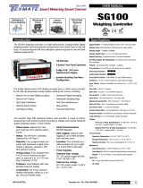
Encoding is done as shown in Figure 1 . The 3GPP and IS2000 turbo encoders employ two recursive,
systematic, convolutional (RSC) encoders connected in parallel, with an interleaver (the turbo interleaver)
preceding the second recursive convolutional encoder. The two recursive convolutional codes are called
the constituent encoders of the turbo code and have a constraint length K = 4.
Figure 1. 3GPP and IS2000 Turbo-Encoder Block Diagram
The outputs of the constituent encoders are punctured and repeated (F denotes the frame size, X and X'
are systematic data, A, B, A', and B' are parity data, X', A', and B' are the interleaved versions of X, A, and
B data):
• Data rate 1/2 (2 × F bits):
X
0
A
0
X
1
A'
1
X
2
A
2
X
3
A'
3
…
• Data rate 1/3 (3 × F bits):
X
0
A
0
A'
0
X
1
A
1
A'
1
X
2
A
2
A'
2
X
3
A
3
A'
3
…
• Date rate 1/4 (4 × F bits):
X
0
A
0
B
0
B'
0
X
1
A
1
A'
1
B'
1
X
2
A
2
B
2
B'
2
X
3
A
3
A'
3
B'
3
…
For the tail bits, the sequence is:
• IS2000 tail rate 1/2 and 3GPP tail rate 1/3: 12 bits
X
F
A
F
X
F+1
A
F+1
X
F+2
A
F+2
X'
F
A'
F
X'
F+1
A'
F+1
X'
F+2
A'
F+2
• IS2000 tail rate 1/3: 18 bits (systematic bit repeated twice)
X
F
X
F
A
F
X
F+1
X
F+1
A
F+1
X
F+2
X
F+2
A
F+2
X'
F
X'
F
A'
F
X'
F+1
X'
F+1
A'
F+1
X'
F+2
X'
F+2
A'
F+2
• IS2000 tail rate 1/4: 24 bits (systematic bit repeated twice)
X
F
X
F
A
F
B
F
X
F+1
X
F+1
A
F+1
B
F+1
X
F+2
X
F+2
A
F+2
B
F+2
X'
F
X'
F
A'
F
B'
F
X'
F+1
X'
F+1
A'
F+1
B'
F+1
X'
F+2
X'
F+2
A'
F+2
B'
F+2
The decoding process is an iterative algorithm based on simple decoders individually matched to the
RSC codes. A generic 3GPP and IS2000 turbo decoder is shown in Figure 2 .
Each decoder sends a posteriori likelihood estimates of the decoded bits to the other decoder, and
10 TMS320C6457 Turbo-Decoder Coprocessor 2 SPRUGK1 – March 2009
Submit Documentation Feedback

MAP1
MAP2
Received systematics
Interleave
Deinterleave
A priori
Interleave
A priori
Received systematics
Received parities
Received parities A’ & B ’ symbols
Hard
decisions
calculation
Decoded bits
X’ symbols
information
X symbols
A & B symbols
information
3 Overview
www.ti.com
Overview
uses the corresponding estimates from the other decoder as a priori likelihood. The a priori information
is seen as beforehand knowledge, meaning that some messages are more likely to occur than others.
A posteriori information adds to the a priori information the knowledge gained by the decoding.
The uncoded information bits (corrupted by the noisy channel) are available to each decoder to
initialize the a priori likelihoods. The decoders use the Maximum a Posteriori (MAP) bitwise decoding
algorithm that requires the same number of states as the well known Viterbi algorithm. The turbo
decoder iterates between the outputs of the two constituent decoders until it reaches satisfactory
convergence. The final output is a hard-quantized version of the likelihood estimates of the decoders.
Figure 2. 3GPP and IS2000 Turbo-Decoder Block Diagram
The DSP controls the operation of the TCP2 (Figure 3 ) using memory-mapped registers. The DSP
typically sends and receives data using synchronized EDMA3 transfers through the 64-bit EDMA3 bus.
The TCP2 sends two synchronization events to the EDMA3: a receive event (TCPREVT) and a transmit
event (TCPXEVT).
The processing unit can implement the Max*-Log-MAP or Max-Log-MAP approximations of the BCJR
algorithm and is selected with the E_MAX_STAR bit of the TCPIC3 register. (See L. R. Bahl, J. Cocke, F.
Jelinek, and J. Raviv, "Optimal decoding of linear codes for minimizing symbol error rate",. IEEE Trans.
Inform.Theory, vol. IT.20, pp. 284.287, Mar. 1974 and P. Robertson, E. Villebrun, and P. Hoeher, "A
comparison of optimal and sub-optimal MAP decoding algorithms operating in the log domain", in Proc.
1996 IEEE Int. Conf. on Communications (Seattle, WA), June 1995, vol. 2, pp. 1009-1013.)
The TCP2 has two fundamental modes: standalone (SA) and shared processing (SP).
In SA mode, the TCP2 iterates a given number of times and outputs hard decisions. In SP mode, the
TCP2 executes a single MAP decode and outputs extrinsic information (soft information). SA mode is
typically used for frame sizes up to 20730. SP mode must be used for frames strictly larger than 20730.
Table 1 describes which mode to use depending on the frame size.
The TCP2 input data corresponds to channel log-likelihood ratios scaled on 6 bits, while the TCP2 output
data to hard-decisions (SA mode) or extrinsics (SP mode) scaled on 7 bits.
SPRUGK1 – March 2009 TMS320C6457 Turbo-Decoder Coprocessor 2 11
Submit Documentation Feedback

32-bit configuration bus
64-bit EDMA3 bus
Turbo-decoder coprocessor (TCP2)
REVT/XEVT
generation
CPU
interrupt
generation
TCP2 control
EDMA3 I/F unit Memory block Processing unit
TCP2_INT TCPXEVT TCPREVT
4 Standalone (SA) Mode
Standalone (SA) Mode
www.ti.com
Figure 3. TCP2 Block Diagram
Table 1. Frame Sizes for Standalone (SA) Mode and
Shared-Processing (SP) Mode
Frame Size (F) TCP2 Mode
40 ⇐ F ⇐ 20730 Standalone mode
F > 20730 Shared processing
In standalone (SA) mode, the DSP sends the systematic and parity data, and the interleaver table. The
TCP2 then works independently of the DSP (standalone), iterates a defined maximum number of times,
and outputs hard decision data. In this mode, minimum DSP processing is required. A stopping criteria
can be enabled to reduce the processing delay (see Section 4.3 ). Figure 4 shows the SA mode.
The standalone mode is used for frames in which the turbo interleaver length is less than or equal to
20730. In this mode, the systematic, parities, extrinsics, and turbo interleaver data fit within the TCP2
memory, and several iterations of decoding are run within the coprocessor without any DSP intervention.
The DSP sets up the EDMA3 to send the systematic and parity data, and the interleaver table (optional).
The TCP2 then works independently of the DSP.
12 TMS320C6457 Turbo-Decoder Coprocessor 2 SPRUGK1 – March 2009
Submit Documentation Feedback

Parity A
Parity A’
Parity B
Parity B’
Void input
I
I
I
−1
Apriori 1
Apriori 2
Systematic
Stop?
(stopping
criterion
algo)
New
apriori
Previous apriori
Yes
Systematic
No
Slicer
Create hard
decisions
End
MAP
decoder
unit
Extrinsic
saved
as new
apriori
Keep on iterations
Enable next log−map
by switching the
switches
4.1 Input Data Format
4.1.1 Systematic and Parity Data
www.ti.com
Standalone (SA) Mode
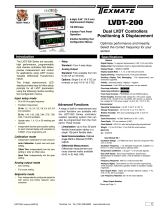
One iteration of turbo decoding consists of 2 MAPs processing, the first MAP with the initial switch position
(as shown in Figure 4 ), the second MAP with the other position of the switch. After each MAP, a stopping
test can be performed based on the following methods. These tests are user configurable.
• Comparing the extrinsic SNR estimate to a SNR threshold (user defined)
• CRC pattern match
• Max iterations
When starting a decoding, you must supply a maximum number of iterations and optionally an SNR
threshold ratio (or CRC) for the stopping test. If the stopping test is positive or the maximum number of
iterations is reached, the decoding stops, the hard decisions are computed (from both extrinsic and
systematic data), and then the coprocessor notifies EDMA3 that the processing is complete. In Figure 4 ,
switch positions are for MAP0 and opposite positions are for MAP1.
Figure 4. Standalone (SA) Mode Block Diagram
Symbols (data) have to be quantized on 6 bits as (4,2) bit numbers, that is, SIII.FF (where S = sign bit, I =
integer bit, F = fractional bit). Depending on the rate, Figure 6 through Figure 16 show how data must be
organized in the DSP memory to conform to a rate that is 1/5 of the input data stream, which TCP2
requires. The base address must be double-word aligned. For big-endian configuration, see the TCP2
endian register (TCPEND) in Section 6.22 . Also note that interleaved parities must be de-interleaved prior
to being sent to TCP2.
SPRUGK1 – March 2009 TMS320C6457 Turbo-Decoder Coprocessor 2 13
Submit Documentation Feedback

Standalone (SA) Mode
www.ti.com
Figure 5. Systematic/Parity Data for Rates 1/2, 1/3, 1/4, 1/5, and 3/4
63:62 61:56 55:50 49:44 43:38 37:32 31:30 29:24 23:18 17:12 11:6 5:0
RSVD SP9 SP8 SP7 SP6 SP5 RSVD SP4 SP3 SP2 SP1 SP0
Figure 6. EN = 1 (Little-Endian Mode) Rate = 1/2
Word Word
N + 1 N
SP9 SP8 SP7 SP6 SP5 SP4 SP3 SP3 SP3 SP0
0 A1' 0 0 X1 0 0 0 0 X0
Word Word
N + 3 N + 2
SP9 SP8 SP7 SP6 SP5 SP4 SP3 SP3 SP3 SP0
0 A3' 0 0 X3 0 0 0 0 X2
Figure 7. EN = 0 (Big-Endian Mode) Rate = 1/2
Word Word
N N + 1
SP4 SP3 SP2 SP1 SP0 SP9 SP8 SP7 SP6 SP5
0 0 0 A0 X0 0 A1' 0 0 X1
Word Word
N + 2 N + 3
SP4 SP3 SP2 SP1 SP0 SP9 SP8 SP7 SP6 SP5
0 0 0 A2 X2 0 A3' 0 0 X3
Figure 8. EN = 1 (Little-Endian Mode) Rate = 1/3
Word Word
N + 1 N
SP9 SP8 SP7 SP6 SP5 SP4 SP3 SP2 SP1 SP0
0 A1' 0 A1 X1 0 A0' 0 A0 X0
Word Word
N + 3 N + 2
SP9 SP8 SP7 SP6 SP5 SP4 SP3 SP2 SP1 SP0
0 A3' 0 A3 X3 0 A2' 0 A2 X2
Figure 9. EN = 0 (Big-Endian Mode) Rate = 1/3
Word Word
N N + 1
SP4 SP3 SP2 SP1 SP0 SP9 SP8 SP7 SP6 SP5
0 A0' 0 A0 X0 0 A1' 0 A1 X1
Word Word
N + 2 N + 3
SP4 SP3 SP2 SP1 SP0 SP9 SP8 SP7 SP6 SP5
0 A2' 0 A2 X2 0 A3' 0 A3 X3
Figure 10. EN = 1 (Little-Endian Mode) Rate = 1/4
Word Word
N + 1 N
SP9 SP8 SP7 SP6 SP5 SP4 SP3 SP2 SP1 SP0
B1' A1' 0 A1 X1 B0' 0 B0 A0 X0
Word Word
N + 3 N + 2
SP9 SP8 SP7 SP6 SP5 SP4 SP3 SP2 SP1 SP0
B3' A3' 0 A3 X3 B2' 0 B2 A2 X2
TMS320C6457 Turbo-Decoder Coprocessor 214 SPRUGK1 – March 2009
Submit Documentation Feedback

www.ti.com
Standalone (SA) Mode
Figure 11. EN = 0 (Big-Endian Mode) Rate = 1/4
Word Word
N N + 1
SP4 SP3 SP2 SP1 SP0 SP9 SP8 SP7 SP6 SP5
B0' 0 B0 A0 X0 B1' A1' 0 A1 X1
Word Word
N + 2 N + 3
SP4 SP3 SP2 SP1 SP0 SP9 SP8 SP7 SP6 SP5
B2' 0 B2 A2 X2 B3' A3' 0 A3 X3
Figure 12. EN = 1 (Little-Endian Mode) Rate = 1/5
Word Word
N + 1 N
SP9 SP8 SP7 SP6 SP5 SP4 SP3 SP2 SP1 SP0
B1' A1' B1 A1 X1 B0' A0' B0 A0 X0
Word Word
N + 3 N + 2
SP9 SP8 SP7 SP6 SP5 SP4 SP3 SP2 SP1 SP0
B3' A3' B3' A3 X3 B2' A2' B2 A2 X2
Figure 13. EN = 0 (Big-Endian Mode) Rate = 1/5
Word Word
N N + 1
SP4 SP3 SP2 SP1 SP0 SP9 SP8 SP7 SP6 SP5
B0' A0' B0 A0 X0 B1' A1' B1 A1 X1
Word Word
N + 2 N + 3
SP4 SP3 SP2 SP1 SP0 SP9 SP8 SP7 SP6 SP5
B2' A2 B2 A2 X2 B3' A3' B3 A3 X3
Figure 14. EN = 1 (Little-Endian Mode) Rate = 3/4
Word Word
N + 1 N
SP9 SP8 SP7 SP6 SP5 SP4 SP3 SP2 SP1 SP0
0 0 0 0 X1 0 0 0 A0 X0
Word Word
N + 3 N + 2
SP9 SP8 SP7 SP6 SP5 SP4 SP3 SP2 SP1 SP0
0 A3' 0 0 X3 0 0 0 0 X2
Word Word
N + 5 N + 4
SP9 SP8 SP7 SP6 SP5 SP4 SP3 SP2 SP1 SP0
0 0 0 0 X3 0 0 0 0 X2
SPRUGK1 – March 2009 TMS320C6457 Turbo-Decoder Coprocessor 2 15
Submit Documentation Feedback

4.1.2 Interleaver Indexes
4.2 Output Decision Data Format
4.3 Stopping Criteria
Standalone (SA) Mode
www.ti.com
Figure 15. Rate 3/4 EN = 0 (Big-Endian Mode) Rate = 3/4
Word Word
N N + 1
SP4 SP3 SP2 SP1 SP0 SP9 SP8 SP7 SP6 SP5
0 0 0 A0 X0 0 0 0 0 X1
Word Word
N + 2 N + 3
SP4 SP3 SP2 SP1 SP0 SP9 SP8 SP7 SP6 SP5
0 0 0 0 X2 0 A3' 0 0 X3
Word Word
N + 4 N + 5
SP4 SP3 SP2 SP1 SP0 SP9 SP8 SP7 SP6 SP5
0 0 0 0 X4 0 0 0 0 X5
Each index is a 15-bit value being effectively saved as 16 bits right-justified. Given an index j, an
interleaver table t, and a data x, the interleaved data x is given as x' = x[ t( j)]. Table 2 shows how data
must be organized in the memory. The base address must be double-word aligned. For big-endian
configurations, see the TCP2 endian register (TCPEND) in Section 6.22 .
Table 2. Interleaver Data
Little_big_endian Endian_intr Description (MSB to LSB)
0 0 1,0,3,2 ⇒ 3,2,1,0 (halfword)
0 1 0,1,2,3 ⇒ 3,2,1,0 (halfword)
1 0 Endianness manager has no effect
3,2,1,0 ⇒ 3,2,1,0 (halfword)
1 1 Endianness manager has no effect
3,2,1,0 ⇒ 3,2,1,0 (halfword)
Hard decisions for TCP2 are 32-bit word-packed. The bit ordering within the 32-bit hard-decision word is
programmable, such that the oldest bit can be either in the MSB or the LSB position. Their destination
storage base address must be double-word aligned. Moreover, the buffer length must contain an even
number of words.
The turbo decoder has an iterative structure, and the number of iterations that are performed for each
frame is either a deterministic number or it depends on a test performed on the turbo decoder output after
each iteration. In the first case, you decide how many iterations should be performed prior to decoding a
frame. In the second case, the turbo decoder performs tests after each iteration to determine whether the
iterative process should continue. In this case, the boundary conditions are programmed (for example, the
minimum and the maximum number of iterations that should be performed). The tests performed are the
SNR stopping criterion and cyclic redundancy check (CRC) iterations passed.
This SNR stopping criterion on TCP2 can be used by setting the SNR threshold from 1 to 100 (0 disables
the SNR threshold check). The stopping criteria is met and a TCPREVT is generated when the SNR
threshold is met, the minimum iterations have been processed, and sufficient CRC iterations have passed,
if CRC is enabled. This indicates that decisions are ready for the EDMA3 to access.
Larger thresholds improve bit-error rate (BER) performance, but require more iterations. Smaller
thresholds require fewer iterations, but may yield poorer BER performance. The actual number of
iterations run can be read from the output parameters.
16 TMS320C6457 Turbo-Decoder Coprocessor 2 SPRUGK1 – March 2009
Submit Documentation Feedback

4.4 Stopping Test Unit
4.4.1 SNR Threshold Termination
4.4.2 CRC Termination
www.ti.com
Standalone (SA) Mode
The CRC-based stopping criterion can be used by setting the CRC polynomial length (CRCLEN) and the
number of CRC iterations required to pass CRCITERPASS. After each iteration, hard decisions are
computed and a CRC is performed. The CRC polynomial is a programmable 32-bit number. To avoid
situations where a CRC test passes for a very noisy frame of data, the hard decisions need to pass the
CRC test for a number of consecutive iterations, which is user-defined via the CRCITERPASS bit field.
Turbo decoders are iterative decoders. Each iteration consists of two MAP decodes except the last
iteration that executes only the first MAP decode. The turbo decoder can iterate up to 32 iterations. The
decoder will continue to iterate until one of the following conditions occur: meet parameter conditions,
CRC passed, or SNR threshold passed.
The stopping criteria algorithm generates the first two moments of the extrinsics, generates an SNR ratio,
and compares the ratio with a threshold. If the calculated ratio exceeds the threshold, then the decoder
has found an optimum solution. The decoder can then stop executing any further iterations. The
calculated SNR ratio is generated after each MAP process. The threshold is a user input and can range
from 0 to 100. Larger thresholds give better results but require more iterations. Smaller thresholds require
fewer iterations and give can give poorer results. Setting the threshold to 0 disables the stopping criteria
algorithm.
The stopping criteria contains two parts. The first part executes on each extrinsic value. The sum of the
extrinsics and the sum of the extrinsics squared are calculated. The second part is executed once at the
end of each MAP block. The first moment is squared and multiplied by the sum of 1 plus the inverse of the
threshold. The second moment is multiplied by the number of symbols per frame. The two results are
compared. If the result is positive, then the stopping criteria has been met.
The turbo decoder will generate a block of extrinsics after each MAP decode. The SNR stopping criteria
block calculates the mean and the variance for this block. It will divide the two and compare the result with
the snr_threshold. If the result is greater then the snr_threshold for two consecutive MAP decodes, then
the decoder will stop executing. The DSP sets the snr_threshold parameter. The SNR stopping criteria
can be turned off with a value of 0. Enabled values for snr_threshold range from 1 to 100. A value of 100
gives the best BER performance at a cost of the most iterations executed, and a value of 1 gives the
worst BER performance at a cost of the fewest iterations. Recommended setting for this parameter is 100.
A frame of data is sent through a CRC block which appends crc_length number of bits to the frame. This
frame is encoded by the turbo encoder. The polynomial for the CRC check is defined with the crc_poly
parameter. The turbo decoder will generate hard decision bits after each non-interleaved MAP decode.
These bits are processed by the CRC block within the decoder. If the last crc_length bits match the CRC
pattern, then the CRC check has passed. The turbo decoder will stop executing after CRCITERPASS
number of consecutive CRC passes as programmed in TCPIC4.
The coefficients and the size of the CRC polynomial are programmable. The size of the polynomial is
defined with the parameter crc_length and can be set from 0 to 32 bits. A value of 0 disables the CRC
check, values between 1 and 32 enable the CRC check. The CRC polynomial is defined with the crc_poly
parameter. The CRC unit will not be enabled until the decoder iteration count is equal or greater than the
min_iter parameter. The turbo decoder will generate hard decisions after each non-interleaved MAP
decode. These bits are processed by the CRC block within the decoder. If the last set of frame bits match
the CRC pattern, then the CRC check has passed. The turbo decoder must pass a number of consecutive
iterations to terminate before max_iter. The number of consecutive iterations passed is defined with the
crc_iter_pass parameter. The crc_iter_pass parameter can be set from 0 to 31, a zero is equal to 1
iteration. The dec_pass output parameter will be set to a 1 if the decoder terminated due to a passing
CRC.
During the sub-block execution, up to 256 sets of data will be stored in a double buffered RAM whose size
is 265x7x2. Two bits each will be stored for x0, p0, and p1. One bit is the sign bit and the other bit is set if
the symbol is equal to a zero. These 6 bits will be used for re-encoding. The seventh bit will be the hard
decision bit. This bit is the sign of the following summation: (x+a+w).
SPRUGK1 – March 2009 TMS320C6457 Turbo-Decoder Coprocessor 2 17
Submit Documentation Feedback

4.4.3 Parameter Termination
4.4.3.1 Maximum Iterations
4.4.3.2 Minimum Iterations
5 Shared-Processing (SP) Mode
Shared-Processing (SP) Mode
www.ti.com
The CRC will process one sub-block at time using the data stored from the previous sub-block. The
decision bit will be used by a CRC block. After all sub-blocks have been processed, the CRC bits in the
CRC block are checked and compared with the last crc_length bits of the frame. If they all match, then the
CRC passes.
The parameters min_iter and max_iter need to be set prior to decode. The decoder must execute min_iter
number of iterations. This parameter can be set from 0 to 31. The decoder will stop executing when the
iteration count equals max_iter. Max_iter can be set from 0 to 31 and must be equal or greater than
min_iter. A zero for max is equal to 32 iterations. A zero for min is equal to 1 iteration.
Turbo decoders execute the MAP decoder twice per iteration. One execution is for non-interleaved data
and the other execution is for interleaved data. This parameter sets the maximum number of decoder
iterations for each block of data. Valid sizes are 0 to 31. If either the CRC passed or the SNR stopping
criteria threshold has been exceeded, then the decoder will stop early. The last iteration will only process
the MAP decoder for the non-interleaved data.
Turbo decoders execute the MAP decoder twice per iteration. One execution is for non-interleaved data
and the other execution is for interleaved data. This parameter sets the minimum number of decoder
iterations for each block of data. Valid sizes are 0 to 31 and the min_iter must be less than or equal to the
max_iter. The CRC unit will not be enabled until the decoder iteration count is equal or greater than the
min_iter parameter. The turbo decoder will not process the CRC, re-encode, or write to the output RAM
until the minimum number of iterations has been reached.
In shared-processing (SP) mode, the DSP sends systematic and parity data, and a priori data. The TCP
performs one single MAP decode and outputs extrinsic data. A priori data for MAP1 is obtained by
de-interleaving the extrinsic data from the previous MAP2, and a priori data for MAP2 is obtained by
interleaving the extrinsics data from the previous MAP1. An overview of the SP mode is shown in
Figure 16 . Note that the systematic and parity data to be sent to the TCP has to be demultiplexed from the
original flow described in Section 5.1 . The DSP must perform the input data demultiplexing, interleaving,
deinterleaving operations, hard decision calculation, and any stopping criteria algorithm.
TMS320C6457 Turbo-Decoder Coprocessor 218 SPRUGK1 – March 2009
Submit Documentation Feedback

MAP
decoder
unit
A for MAP 1
and A’ for MAP2
B for MAP1
and B’ for MAP2
(only rate 1/4)
X for MAP1
or X’ for MAP2
EXT
1
: extrinsics after MAP1
EXT
2
: extrinsics after MAP2
EXT
1,2
www.ti.com
Shared-Processing (SP) Mode
Figure 16. Shared-Processing (SP) Mode Block Diagram
The shared-processing mode allows the DSP/TCP2 system to support frames strictly larger than 20730.
The DSP breaks the large frame into 2 or more smaller frames of 20480 or less. Each frame is called a
subframe. The size of all the subframes (except the last subframe) must be divisible by 256. The DSP
breaks the large frame into several sub-frames following the process shown below. The first subframe
does not have a header section and its tail section is equal to the prolog size. The middle subframe
header and tail section sizes are each equal to the prolog size. The last subframe header size is equal to
the prolog size and the tail section is equal to the tail size. The prolog size must be integer divisible by 8.
The sub-frames reliability portions are sequenced in order to create the full frame.
1. The first subframe (required) will have a opmode of 1. The middle subframe(s) (optional) have a
opmode of 2. The last subframe (required) will have a opmode of 3.
2. The size of all the subframes (except the last subframe) must be integer divisible by 256 and Max sub
frame size = 20480 = 80*256.
3. The first and middle subframes should have the same size. The last subframe should be approximately
the same size as the other subframes.
4. The last subframe size must be at least 129.
SPRUGK1 – March 2009 TMS320C6457 Turbo-Decoder Coprocessor 2 19
Submit Documentation Feedback

Num
Subframe
+ CEIL
ǒ
Size
Block
Size
MAX_Subframe
Ǔ
Size
Subframe
+ CEIL
ǒ
Size
Block
256 Num
Subframe
Ǔ
256
while
ǒ
Size
Block
u Size
MAX_Subsystem
Ǔ
{
Size
Block
+ Size
Block
* Size
Subframe
if
(
Size
Block
u 128
)
}
Size
Last_Subframe
+ Size
Block
if
(
Size
Block
v 128
)
Num
Subframe
+ Num
Subframe
* 1
Size
Last_Subframe
+ Size
Block
) Size
MAX_Subframe
{
}
}
1st sub−frame:
Prolog header is transferred by EDMA3, but not used by the TCP:
The TCP EDMA3 I/F unit reads and counts this data but does not
store it into the coprocessor memory.
Actually, the TCP is using the frame header symbols and does not
need any header prolog computation.
Last sub−frame
A full sub−frame including the header and tail prolog is transferred by EDMA3
but the totality is not used by the TCP.
For the useless sub−frame part, the TCP EDMA3 I/F unit reads and counts it
Actually, the TCP is using the frame tail symbol and does not need any
tail prolog computation.
Full frame (frame length >20730)
1st sub−frame
Middle sub−frame
Middle sub−frame
Last
sub−frame
but does not store it into the coprocessor memory.
Shared-Processing (SP) Mode
www.ti.com
Figure 17. Subframe Equations
Figure 18. Frame Process
20 TMS320C6457 Turbo-Decoder Coprocessor 2 SPRUGK1 – March 2009
Submit Documentation Feedback
/