14
ASSEMBLY AND PREPARATION
ENGLISH
• Disconnect the power cord before moving or
installing the monitor to avoid risk of electric
shock.
• If you install the monitor on a ceiling or slanted
wall, it may fall and result in injury. Use an
authorized LG wall mount and contact your
local dealer or qualified personnel to assist with
the installation.
• Do not over tighten the screws as this may
damage the monitor and void your warranty.
• Use only screws and wall mounting brackets
that meet the VESA standard. Any damage or
injuries caused by misuse or use of improper
accessories are not covered by the warranty.
• To prevent injury, this apparatus must be
securely attached to the wall in accordance
with the installation instructions. (This pertains
only to Australia and New Zealand.)
• The wall mount kit includes the installation
guide and all necessary parts.
• The wall mounting bracket is optional. You can
obtain additional accessories from your local
dealer.
• The length of screws required may differ
depending on the wall mount. Be sure to use
the correct length.
• For more information, please refer to the guide
provided with the wall mount.
• The warranty will not cover any damages
caused by using the product in an excessively
dusty environment.
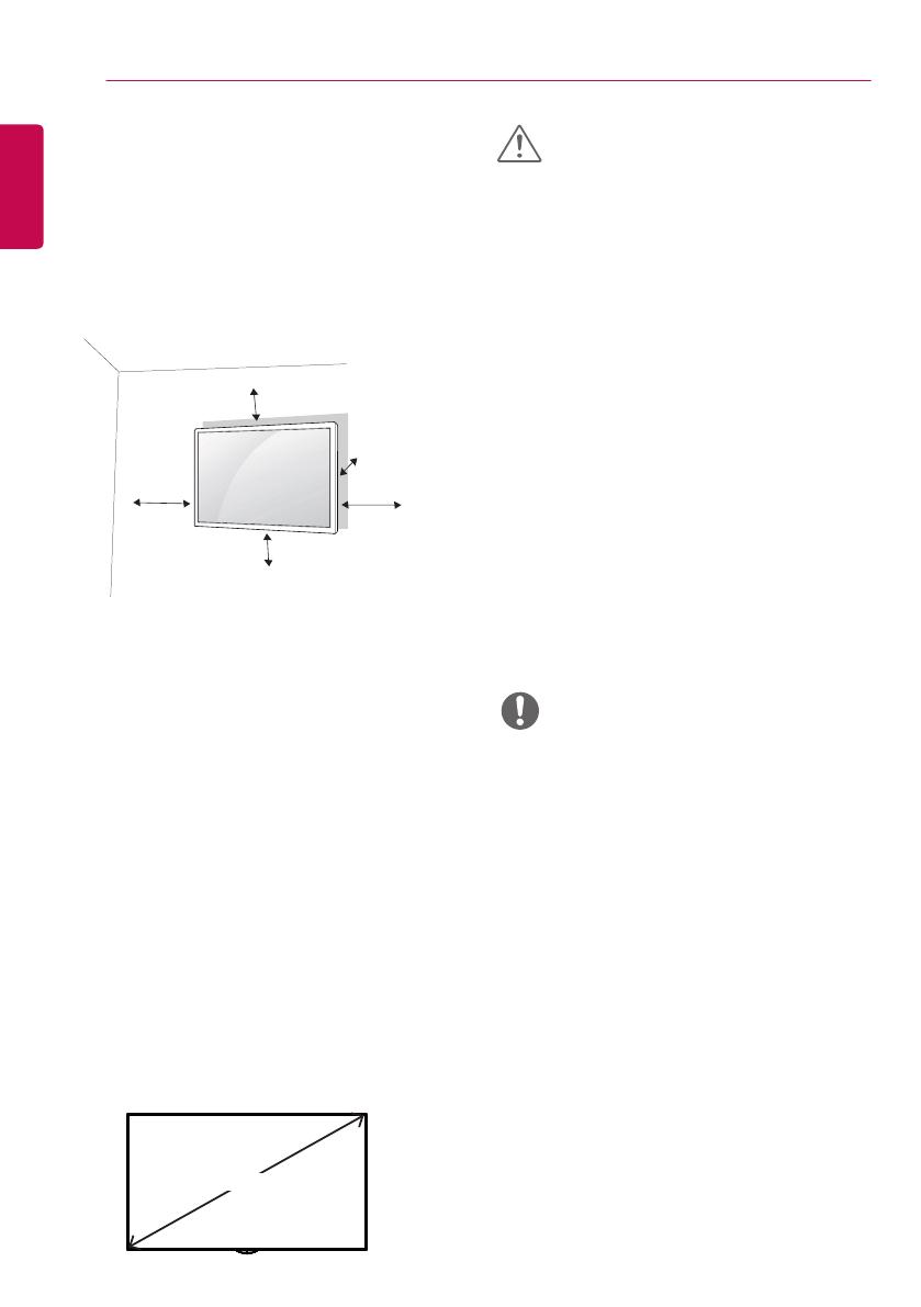
Installing on a Wall
For proper ventilation, allow a clearance of
10 cm on each side and from the wall. Detailed
installation instructions are available from your
dealer, see the optional Tilt Wall Mounting Bracket
Installation and Setup Guide.
To install your monitor on a wall, attach a wall
mounting bracket (optional part) to the back of the
monitor.
Make sure that the wall mounting bracket is
securely fixed to the monitor and to the wall.
1 Use only screws and wall mounting brackets
that conform to VESA standards.
2 Screws which are longer than standard length
may damage the inside of the monitor.
3 A non-VESA standard screw may damage
the product and cause the monitor to fall. LG
Electronics is not liable for any accidents related
to the use of non-standard screws.
4 Please use VESA standard as below.
• 785 mm and above
* Fixing screws: Diameter 6.0 mm x
Pitch 1.0 mm x Length 12 mm
10 cm
10 cm
10 cm
10 cm
10 cm
CAUTION
NOTE
785 mm


