Page is loading ...

1
Operating Instructions and Parts Manual
Dual Station Abrasive Notcher
Models: DSAN4-1, DSAN4-3
JET
427 New Sanford Road
LaVergne, Tennessee 37086 Part No. M-756180
Ph.: 800-274-6848 Edition 4 04/2019
www.jettools.com Copyright © 2017 JET
This .pdf document is bookmarked

2
1.0 IMPORTANT SAFETY
INSTRUCTIONS
WARNING – To reduce risk of injury:
1. Read and understand the entire owner's
manual before attempting assembly or
operation.
2. Read and understand the warnings posted on
the machine and in this manual. Failure to
comply with all of these warnings may cause
serious injury.
3. Replace the warning labels if they become
obscured or removed.
4. This Abrasive Notcher is designed and intended
for use by properly trained and experienced
personnel only. The manual is not, nor was it
intended to be, a training manual. If you are not
familiar with the proper and safe operation of an
abrasive notcher do not use until proper training
and knowledge have been obtained.
5. Do not use this machine for other than its
intended use. If used for other purposes, JET
disclaims any real or implied warranty and holds
itself harmless from any injury that may result
from that use.
6. Always wear protective eye wear when
operating machinery. Eye wear shall be impact
resistant, protective safety glasses with side
shields which comply with ANSI Z87.1
specifications. Use of eye wear which does not
comply with ANSI Z87.1 specifications could
result in severe injury from breakage of eye
protection. (Everyday eyeglasses only have
impact resistant lenses; they are NOT safety
glasses.)
7. Before operating this machine, remove tie,
rings, watches and other jewelry, and roll
sleeves up past the elbows. Do not wear loose
clothing. Confine long hair. Non-slip footwear or
anti-skid floor strips are recommended.
8. Wear protective footwear, such as steel-toed
shoes, when working with metal materials.
9. Wear ear protectors (plugs or muffs) if sound
exceeds safe levels.
10. Make certain the switch is in the OFF position
before connecting the machine to the power
supply.
11. Make certain the machine is properly grounded.
12. Make all machine adjustments or maintenance
with the machine disconnected from the power
source.
13. Remove adjusting keys and wrenches. Form a
habit of checking to see that keys and adjusting
wrenches are removed from the machine
before turning it on.
14. Keep safety guards in place at all times when
the machine is in use. If removed for
maintenance purposes, use extreme caution
and replace the guards immediately after
completion of maintenance.
15. Check damaged parts. Before further use of the
machine, a guard or other part that is damaged
should be carefully checked to determine that it
will operate properly and perform its intended
function. Check for alignment of moving parts,
binding of moving parts, breakage of parts,
mounting and any other conditions that may
affect its operation. A guard or other part that is
damaged should be properly repaired or
replaced.
16. Provide for adequate space surrounding work
area and non-glare, overhead lighting.
17. Keep the floor around the machine clean and
free of scrap material, oil and grease.
18. Keep visitors a safe distance from the work
area. Keep children away.
19. Make your workshop child proof with padlocks,
master switches or by removing starter keys.
20. Give your work undivided attention. Looking
around, carrying on a conversation and “horse-
play” are careless acts that can result in serious
injury.
21. Maintain a balanced stance at all times so that
you do not fall into the abrasive belt or other
moving parts. Do not overreach or use
excessive force to perform any machine
operation.
22. Use the right tool at the correct speed and feed
rate. Do not force a tool or attachment to do a
job for which it was not designed. The right tool
will do the job better and more safely.
23. Feed work into a blade or cutter against the
direction of rotation of the blade or cutter only.
24. Use recommended accessories; improper
accessories may be hazardous.
25. Maintain tools with care. Keep abrasive belt
clean for the best and safest performance.
Follow instructions for lubricating and changing
accessories.
26. Turn off the machine before cleaning. Use a
brush, compressed air, or vacuum to remove
chips or debris — do not use bare hands.

3
27. Do not stand on the machine. Serious injury
could occur if the machine tips over.
28. Never leave the machine running unattended.
Turn the power off and do not leave the
machine until it comes to a complete stop.
29. Remove loose items and unnecessary work
pieces from the area before starting the
machine.
30. Do not place hands near abrasive belt while
machine is operating.
31. Don’t use in dangerous environment. Don’t use
power tools in damp or wet location, or expose
them to rain. Keep work area well lighted.
32. Use proper extension cord. Make sure your
extension cord is in good condition. When using
an extension cord, use one heavy enough to
carry the current your product will draw. An
undersized cord will cause a drop in line voltage
resulting in loss of power and overheating. Sect.
6.3, Table 2 shows correct size to use
depending upon cord length and nameplate
ampere rating. If in doubt, use the next heavier
gauge. The smaller the gauge number, the
heavier the cord.
Familiarize yourself with the following safety notices used in this manual:
This means that if precautions are not heeded, it may result in minor injury and/or possible
machine damage.
This means that if precautions are not heeded, it may result in serious, or possibly even fatal,
injury.
2.0 About this manual
This manual is provided by JET, covering the safe operation and maintenance procedures for the JET DSAN4-
series Abrasive Notchers. This manual contains instructions on installation, safety precautions, general operating
procedures, maintenance instructions and parts breakdown. Your machine has been designed and constructed
to provide consistent, long-term operation if used in accordance with the instructions as set forth in this document.
If there are questions or comments, please contact your local supplier or JET. JET can also be reached at our
web site: www.jettools.com.
Retain this manual for future reference. If the machine transfers ownership, the manual should accompany it.
Read and understand the entire contents of this manual before attempting assembly or
operation! Failure to comply may cause serious injury!
Register your product using the mail-in card provided, or register online –
http://www.jettools.com/us/en/service-and-support/product-registration/
WARNING: This product can expose you to
chemicals including lead which is known to the
State of California to cause cancer and birth
defects or other reproductive harm. For more
information go to http://www.p65warnings.ca.
gov.
WARNING: Some dust, fumes and gases
created by power sanding, sawing, grinding,
drilling, welding and other construction activities
contain chemicals known to the State of
California to cause cancer and birth defects or
other reproductive harm. Some examples of
these chemicals are:
lead from lead based paint
crystalline silica from bricks, cement and other
masonry products
arsenic and chromium from chemically treated
lumber
Your risk of exposure varies, depending on how
often you do this type of work. To reduce your
exposure to these chemicals, work in a well-
ventilated area and work with approved safety
equipment, such as dust masks that are
specifically designed to filter out microscopic
particles. For more information go to
http://www.p65warnings.ca.gov/ and http://
www.p65warnings.ca.gov/wood.

4
3.0 Table of contents
Section Page
1.0 IMPORTANT SAFETY INSTRUCTIONS ....................................................................................................... 2
2.0 About this manual .......................................................................................................................................... 3
3.0 Table of contents ............................................................................................................................................ 4
4.0 Specifications for DSAN4-series Abrasive Notchers ...................................................................................... 5
4.1 Base mounting hole centers ....................................................................................................................... 6
5.0 Setup and assembly ....................................................................................................................................... 7
5.1 Shipping contents ....................................................................................................................................... 7
5.2 Unpacking and locating .............................................................................................................................. 7
6.0 Electrical connections .................................................................................................................................... 7
6.1 Converting to 460V (DSAN4-3 only) .......................................................................................................... 7
6.2 GROUNDING INSTRUCTIONS ................................................................................................................. 8
6.3 Extension cords .......................................................................................................................................... 8
7.0 Adjustments ................................................................................................................................................... 8
7.1 Dust and chip collection ............................................................................................................................. 8
7.2 Jaw adjustments ......................................................................................................................................... 8
7.3 Wheel grinding ........................................................................................................................................... 9
7.4 Changing abrasive belts ............................................................................................................................. 9
7.5 Removing/installing rollers ......................................................................................................................... 9
7.6 Belt tracking ................................................................................................................................................ 9
7.7 Adjustable handles ................................................................................................................................... 10
8.0 Operation ..................................................................................................................................................... 10
8.1 Operating controls .................................................................................................................................... 10
9.0 User-maintenance ........................................................................................................................................ 10
9.1 General maintenance ............................................................................................................................... 10
9.2 Lubrication ................................................................................................................................................ 10
9.3 Additional servicing .................................................................................................................................. 10
10.0 Troubleshooting DSAN4-series Abrasive Notchers ................................................................................... 11
11.0 Replacement Parts ..................................................................................................................................... 12
11.1.1 DSAN4-1,-3 Dual Station Notchers – Exploded View ......................................................................... 12
11.1.2 DSAN4-1,-3 Dual Station Abrasive Notchers – Parts List ................................................................... 13
12.0 Electrical Connections, DSAN4 series Abrasive Notcher .......................................................................... 16
12.1 Wiring Diagram for DSAN4-1 (230V-1PH) ............................................................................................. 16
12.2 Wiring Diagram for DSAN4-3 (230V 3PH) ............................................................................................. 17
12.3 Wiring Diagram for DSAN4-3 (460V 3PH) ............................................................................................. 18
13.0 Warranty and service ................................................................................................................................. 19

5
4.0 Specifications for DSAN4-series Abrasive Notchers
Table 1
Model number
756180 756185
Stock number DSAN4-1 DSAN4-3
Motor and Electricals
Motor type Non-totally-enclosed, fan-cooled, AC induction
Horsepower 4 HP (3.0 kW)
Motor Phase 1 3
Motor Voltage 230V 230/460V (prewired 230V)
1
Cycle 60 Hz
Listed FLA (full load amps) 16 A
10.5/5.5 A
Starting amps
58 A 46/23 A
Running amps (no load)
6.34 A 3.46/2.81 A
Start capacitor
300F 300VAC
n/a
Run capacitor
60F 450VAC
n/a
Motor speed 3400 RPM
Power transfer Direct drive
Power cord
SJT 3x3.31mm
2
12AWG 300V,
L: 3000mm (10 ft.)
SJT 4x2.08mm
2
14AWG 600V,
L: 3000mm (10 ft.)
Power plug Not included
Recommended circuit size
2
25 A 15 A
Sound emission without load
3
85 dB at 1.5m from machine
Capacities
Belt speed 115.6 fps
Belt direction Fwd and Rev
Pipe notching capacity, OD 1/2 to 2-1/2 in.
Notching angle 30 deg. to 90 deg.
Main materials
Belts provided Zirconium, closed coat, 36/60/80G
Main body, column and base Sheet metal
Dimensions
Belt size 79 x 4 in. (2000 x 100 mm)
Standard rolls
4
NPS Ø: 1/2, 3/4, 1, 1-1/4, 1-1/2, 2, 2-1/2 in.; L=4-3/4 in. (120.7 mm)
Working height 43-3/8 in. (1100 mm)
Drive wheel diameter 7-11/16 in. (195 mm)
Dust ports (2) 3 in. OD
Footprint/Base dimensions LxW 20 x 27-7/8 in. (508 x 710 mm)
Overall assembled LxWxH 48 x 24 x 47 in. (1200 x 600 x 1180 mm)
Shipping dimensions LxWxH 56 x 33-1/2 x 57-1/2 in. (1420 x 850 x 1460 mm)
Weights
Net weight 344 lbs (155 kg)
Shipping weight 510 lbs (230 kg)
1
conversion to 460-volt requires additional purchase and installation of DSAN4-3-128-460, Thermal Relay.
2
subject to local and national electrical codes.
3
The specified values are emission levels and are not necessarily to be seen as safe operating levels. As workplace
conditions vary, this information is intended to allow the user to make a better estimation of the hazards and risks
involved only.
4
Diameters are nominal pipe size; see parts list for actual physical dimensions.
L = length, W = width, H = height OD = outside diameter n/a = not applicable fps = feet per second
The specifications in this manual were current at time of publication, but because of our policy of continuous
improvement, JET reserves the right to change specifications at any time and without prior notice, without incurring
obligations.

6
4.1 Base mounting hole centers
Figure 4-1

7
Read and understand all
assembly and setup instructions before
attempting assembly. Failure to comply may
cause serious injury.
5.0 Setup and assembly
5.1 Shipping contents
See Figure 5-1
1 Abrasive Notcher
1 Abrasive belt (80-grit) preinstalled
1 Set of 3 abrasive belts (36,60,80-grit)*
7 Rollers (one roller is pre-installed)
1 Open end wrench, 22/24mm
3 Hex wrenches, 4,6,8 mm
1 Operating instructions and parts list
1 Product registration card
5.2 Unpacking and locating
1. Inspect contents for shipping damage. Report
damage, if any, to your distributor. Do not
discard shipping materials until Notcher is set
up and running properly.
2. Compare contents of shipping carton with the
contents list above. Report shortages, if any, to
your distributor.
3. The Abrasive Notcher should be located on a
sturdy, level floor in a dry environment, with
good overhead lighting and room enough for
loading and offloading of stock, and general
maintenance.
4. Lift machine using hook or straps through lifting
plate (Figure 5-1). Make sure lifting equipment
capacity exceeds maximum weight of Notcher.
Machine is heavy; use
appropriate lifting device and exercise
caution when moving to final location.
Failure to comply may cause serious injury.
Figure 5-1
5. It is recommended that Notcher be bolted to
floor, using lag screws or similar means. See
mounting pattern, Figure 4.1.
6. Remove rust protectant from exposed surfaces
with a clean rag and cleaner/degreaser or
kerosene. Avoid getting solvents on rubber or
plastic parts.
IMPORTANT: The vise handle (see A, Figure 7-1)
has been tightened for shipping purposes. To allow
proper operation, loosen screw (A
1
, Figure 7-1)
about two revolutions.
6.0 Electrical connections
Electrical connections must be
made by a qualified electrician in compliance
with all relevant codes. This machine must be
properly grounded to help prevent electrical
shock and possible fatal injury.
The DSAN4-1 is pre-wired for 230 volt, single-
phase operation. It is recommended that the
DSAN4-1 be connected to a dedicated 25 amp
circuit with circuit breaker or fuse.
The DSAN4-3 is prewired for 230 volt, three-phase
operation, but can be converted to 460 volt, three-
phase operation (see sect. 6.1). It is recommended
that the DSAN4-3 be connected to a dedicated 15
amp circuit with a circuit breaker or fuse.
NOTE: Local codes take precedence over
recommendations.
These machines are not provided with a power plug;
you may either attach a proper UL/CSA-listed plug,
or “hardwire” the machine directly to a service panel
(make sure a disconnect is available to the
operator).
If hardwired:
Permanently connected tools: This tool should be
connected to a grounded metal permanent wiring
system; or to a system having an equipment-
grounding conductor.
6.1 Converting to 460V (DSAN4-3
only)
The DSAN4-3 (3 phase model) can be converted to
460 volt input, as follows:
1. Disconnect machine from power source.
2. Remove rear panel, and replace the 230-volt
thermal relay with a 460-volt thermal relay (part
no. DSAN4-3-128-460, contact JET to order).
3. Reconnect the wires on the transformer from
230V to 460V position. See sect. 12.0
diagrams.

8
4. Connect the motor leads to the incoming power
source, according to the diagram on inside
cover of motor junction box. Similar diagrams
are in sect. 12.0 of this manual.
5. If using a plug, replace the 230V plug with a
proper 460V, UL/CSA-listed plug.
6. Turn on machine (see sect. 8.1 for controls). If
abrasive belt moves wrong direction from that
shown on operating panel (Figure 8-1),
disconnect from power and switch any two of
the 3 wires to the motor (not the green ground
wire).
7. Reinstall rear panel before operating.
6.2 GROUNDING INSTRUCTIONS
This tool must be grounded. In the event of a
malfunction or breakdown, grounding provides a
path of least resistance for electric current to reduce
the risk of electric shock. This tool is equipped with
an electric cord having an equipment-grounding
conductor. If a plug is used, it must be inserted into
an appropriate outlet that is properly installed and
grounded in accordance with all local codes and
ordinances.
Improper connection of the
equipment-grounding conductor can result in a
risk of electric shock. Check with a qualified
electrician or service person if you are in doubt
as to whether the outlet is properly grounded.
Do not modify the plug – if it will not fit the outlet,
have a proper outlet installed by a qualified
electrician.
The conductor with insulation having an outer
surface that is green with or without yellow stripes is
the equipment-grounding conductor. If repair or
replacement of the electric cord or plug is
necessary, do not connect the equipment-grounding
conductor to a live terminal.
Repair or replace damaged or worn cord
immediately.
6.3 Extension cords
The use of extension cords is discouraged; try to
position equipment within reach of the power
source. If an extension cord becomes necessary, be
sure it is heavy enough to carry the current your
product will draw. An undersized cord will cause a
drop in line voltage resulting in loss of power and
overheating.
Table 2 shows recommended size to use depending
on cord length and nameplate ampere rating. If in
doubt, use the next heavier gauge. The smaller the
gauge number, the heavier the cord.
Ampere
Rating
Volts
Total length of
cord in feet
More
Than
Not
More
Than
240 50 100 200 300
AWG
00 06 18 16 16 14
06 10 18 16 14 12
10 12 16 16 14 12
12 16 14 12
Not
Recommended
Extension Cord Recommendations
Table 2
7.0 Adjustments
Disconnect machine from
power source before making adjustments,
unless indicated otherwise.
7.1 Dust and chip collection
The chip boxes (see F, Figure 7-2) are located to
catch swarf/chips at point of workpiece contact. The
box near the jaw assembly freely slides in and out;
the box beneath the wheel grinder is secured by a
screw.
The circular plate at bottom of each chip box can be
removed to connect a dust collection hose using a
hose clamp. It is strongly recommended that a dust
collection system (not provided) suitable for metal
working be used with the Notcher.
7.2 Jaw adjustments
See Figure 7-1.
Handle (A) – Moves jaw assembly toward and away
from belt. Adjust handle sensitivity by loosening or
tightening socket head screw (A
1
) beneath handle.
Locking lever (B) – Push to right to lock lateral slide;
left to unlock.
Handle (C) – Rotate to move floating jaw.
Angle locking screw (D) – Loosen to rotate jaw
assembly for angular work. Refer to adjoining angle
scale. Always tighten screw before operating.
Workstop assembly (E) – Loosen handle to adjust.

9
Figure 7-1
7.3 Wheel grinding
For safety, gap between table
and grinding wheel should not exceed 1/16-inch
(1.6mm).
Adjust table (G, Figure 7-2) into position and tighten
handle (H).
When finished using grinding wheel, adjust table so
that guard can be closed completely, as shown in
Figure 7-2b.
Figure 7-2
7.4 Changing abrasive belts
1. Disconnect machine from power source.
2. Open side and top covers.
3. Remove tension from belt by rotating
handwheel (J, Figure 7-3) counterclockwise.
4. Tension belt with handwheel (J).
5. Track belt. See sect. 7.6.
6. Close all covers.
Figure 7-3
7.5 Removing/installing rollers
1. Disconnect machine from power source.
2. Remove tension from abrasive belt (J, Figure 7-
3).
3. Loosen hex nuts (K, Figure 7-4) and turn set
screws (L) to lower steel balls (M).
4. Slide out roller and insert new roller.
5. Raise balls (M) by turning set screws (L), tighten
hex nuts (K), and tension belt.
The additional rollers can be stored on the rack
within the column – open column door to access.
Figure 7-4
7.6 Belt tracking
1. Loosen hex nut (N
1
, Figure 7-3) counter-
clockwise.
2. Open top cover and move abrasive belt by hand
to observe tracking.
3. Rotate knob (N
2
) as needed to adjust.
4. Tighten nut (N
1
) against machine to secure
setting.
5. Connect to power and run the machine to verify
the setting. Make further adjustments if needed.

10
7.7 Adjustable handles
The handles (such as C, Figure 7-1) can be adjusted
to more convenient position; lift up handle and rotate
it on the pin, then release, making sure it reseats on
pin.
8.0 Operation
8.1 Operating controls
Refer to Figure 8-1.
Figure 8-1
A – Main on/off switch: Turns on main power to
machine.
B – Direction switch: Controls belt direction, center
position is neutral (belt does not move). To prevent
build-up of chips and debris on the belt, use
appropriate belt direction for each operation:
Notching – Direction 1
Grinding side – Direction 2
Grinding top – Direction 2
C – On button: Starts belt movement.
D – Off button: Stops belt movement.
E – Emergency stop button: Press for fast shut-
down of machine functions. To restart machine,
rotate button clockwise until it disengages.
9.0 User-maintenance
Always disconnect power to
machine before performing maintenance.
Failure to do this may result in serious personal
injury.
9.1 General maintenance
1. After each use, vacuum abrasive debris from
machine area. Wipe down machine with a clean
rag and apply light coat of oil to exposed metal
surfaces to inhibit rust.
2. Keep notching table and guide shaft areas
clean and free of debris. Use a brush to clear
shavings, not bare hands.
9.2 Lubrication
Note: Roller bearings are sealed and do not require
further lubrication.
See Figures 9-1 and 9-2.
1. Apply oil or grease to tension leadscrew and
contact points at hex nut.
2. Apply oil or grease to jaw leadscrew.
3. Apply grease to swivel base area.
4. Clean and apply oil to long and short guide
shafts.
Figure 9-1
Figure 9-2
9.3 Additional servicing
Any additional servicing should be performed by
authorized service personnel.

11
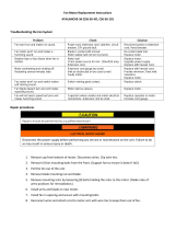
10.0 Troubleshooting DSAN4-series Abrasive Notchers
Table 3
Symptom Possible Cause Correction*
Motor will not start. Low voltage. Check power line for proper voltage.
Open circuit in motor or loose
connection.
Inspect all lead connections on motor for
loose or open connections.
On/Off switch failure. Inspect switch, replace if needed.
Centrifugal switch failure (won’t close
to activate start capacitor).
Replace centrifugal switch.
Run capacitor failure. Replace run capacitor.
Motor fault. Have motor tested by qualified personnel.
Motor will not start:
fuses blow or circuit
breakers trip.
Short circuit in line cord or plug. Inspect cord or plug for damaged
insulation and shorted wires.
Short circuit in motor or loose
connections.
Inspect all connections on motor for loose
or shorted terminals or worn insulation.
Incorrect fuses or circuit breakers in
power line.
Install correct fuses or circuit breakers.
Motor overheats. Motor overloaded. Reduce pressure of material against
abrasive belt.
Air circulation through motor is
restricted.
Clean motor fan with compressed air to
restore normal air circulation.
Prolonged operation. Allow machine to cool.
Motor fault. Have motor tested by qualified personnel.
Motor stalls, or doesn’t
build to normal
operating speed.
Motor overloaded. Reduce pressure of material against
abrasive belt.
Short circuit in motor or loose
connections.
Inspect connections on motor for loose or
shorted terminals or worn insulation.
Low voltage. Correct the low voltage conditions.
Incorrect fuses or circuit breakers in
power line.
Install correct fuses or circuit breakers.
Motor fault. Have motor tested by qualified personnel.
Frequent start
capacitor failure.
Centrifugal switch failure (won’t open
to disengage capacitor, thus causing
constant energizing and premature
wear of capacitor).
Replace centrifugal switch.
Poor notching or
grinding performance.
Abrasive belt slipping on
roller/wheel.
Tighten belt.
Excessive vibration or
noise.
Machine not level on floor. Level machine; use shims if needed.
Loose motor fan. Inspect and tighten.
Motor imbalance. Have motor tested by qualified personnel.
*Warning: Some corrections may require a qualified electrician.

12
11.0 Replacement Parts
To order parts or reach our service department, call 1-800-274-6848 Monday through Friday, 8:00 a.m. to 5:00
p.m. CST. Having the Model Number and Serial Number of your machine available when you call will allow us to
serve you quickly and accurately.
Non-proprietary parts, such as fasteners, can be found at local hardware stores, or may be ordered from JET.
Some parts are shown for reference only, and may not be available individually.
11.1.1 DSAN4-1,-3 Dual Station Notchers – Exploded View

13
11.1.2 DSAN4-1,-3 Dual Station Abrasive Notchers – Parts List
Index No. Part No. Description Size Qty
1 ................ DSAN4-1-1 ................ Guide Seat ............................................................... ...................................... 1
2 ................ DSAN4-1-2 ................ Sliding Plate ............................................................. ...................................... 1
3 ................ DSAN4-1-3 ................ Short Guide Shaft .................................................... 6-5/8"L .......................... 2
4 ................ DSAN4-1-4 ................ Long Guide Shaft ..................................................... 10"L ............................... 2
5 ................ DSAN4-1-5 ................ Upper Sliding Block ................................................. ...................................... 1
6 ................ DSAN4-1-6 ................ Small Sliding Block .................................................. ...................................... 1
7 ................ DSAN4-1-7 ................ Swivel Base ............................................................. ...................................... 1
8 ................ DSAN4-1-8 ................ Jaw Box ................................................................... ...................................... 1
9 ................ DSAN4-1-9 ................ Nut Block ................................................................. ...................................... 1
10 .............. DSAN41-10 ............... Lock Screw .............................................................. ...................................... 1
11 .............. DSAN4-1-11 .............. Locking Disc ............................................................ ...................................... 1
12 .............. DSAN4-1-12 .............. Lead Screw .............................................................. ...................................... 1
13 .............. DSAN4-1-13 .............. Fixed Jaw ................................................................ ...................................... 1
14 .............. DSAN4-1-14 .............. Clamping Plate ........................................................ ...................................... 2
15 .............. DSAN4-1-15 .............. Bottom Sliding Block ................................................ ...................................... 1
16 .............. DSAN4-1-16 .............. Locking Screw ......................................................... ...................................... 1
17 .............. DSAN4-1-17 .............. Block ........................................................................ ...................................... 1
18 .............. DSAN4-1-18 .............. Feeding Handle with Grip (includes #86) ................ ...................................... 1
19 .............. DSAN4-1-19 .............. Roller Bracket .......................................................... ...................................... 1
20 .............. DSAN4-1-20 .............. NPS 1" Roller ........................................................... Ø1-1/4"x4-1/2" L ........... 1
21 .............. DSAN4-1-21 .............. Support Sleeve ........................................................ ...................................... 1
22 .............. TS-1550071 .............. Flat Washer ............................................................. M10 ............................... 1
23 .............. DSAN4-1-23 .............. Fixed Shaft .............................................................. ...................................... 1
24 .............. DSAN4-1-24 .............. Motor Bracket .......................................................... ...................................... 1
25 .............. DSAN4-1-25 .............. Tension Block .......................................................... ...................................... 1
26 .............. DSAN4-1-26 .............. Washer .................................................................... ...................................... 2
27 .............. DSAN4-1-27 .............. Driving Wheel .......................................................... ...................................... 1
28 .............. DSAN4-1-28 .............. Side Cover ............................................................... ...................................... 1
29 .............. DSAN4-1-29 .............. Bottom Fixed Pin ..................................................... ...................................... 1
30 .............. DSAN4-1-30 .............. Upper Fixed Pin ....................................................... ...................................... 1
31 .............. DSAN4-1-31 .............. Chip Box .................................................................. ...................................... 2
32 .............. DSAN4-1-32 .............. Upper Frame ........................................................... ...................................... 1
33 .............. DSAN4-1-33 .............. Long Lead Screw ..................................................... ...................................... 1
34 .............. DSAN4-1-34 .............. Guard ....................................................................... ...
................................... 1
35 .............. DSAN4-1-35 .............. Belt Guiding Shaft .................................................... ...................................... 1
36 .............. DSAN4-1-36 .............. Lifting Plate .............................................................. ...................................... 1
37 .............. DSAN4-1-37 .............. Hex Nut with Set Screw (includes #66) ................... M16-2.0 ......................... 3
38 .............. DSAN4-1-38 .............. Graphite Platen ........................................................ ...................................... 1
39 .............. DSAN4-1-39 .............. Storage Door ........................................................... ...................................... 1
40 .............. DSAN4-1-40 .............. Column .................................................................... ...................................... 1
41 .............. DSAN4-1-41 .............. Base ........................................................................ ...................................... 1
42 .............. DSAN4-1-42 .............. Plate ........................................................................ ...................................... 1
43 .............. TS-1490031 .............. Hex Cap Screw ........................................................ M8-1.25x20 ................. 12
44 .............. DSAN4-1-44 .............. Adjustable Handle ................................................... M10-1.5x25 ................... 1
45 .............. TS-1504041 .............. Socket HD Cap Screw ............................................. M8-1.25x20 ................... 2
46 .............. JEB-137 .................... Hex Cap Screw ........................................................ M8-1.25x100 ................. 1
47 .............. F009489 .................... Hex Cap Screw BO ................................................. M10-1.5x20 ................... 4
48 .............. TS-1491031 .............. Hex Cap Screw ........................................................ M10-1.5x25 ................... 5
49 .............. TS-1491031 .............. Hex Cap Screw ........................................................ M10-1.5x25 ................... 1
50 .............. TS-2210451 .............. Hex Cap Screw ........................................................ M10-1.5x45 ................... 1
51 .............. TS-1492041 .............. Hex Cap Screw ........................................................ M12-1.75x40 ................. 1
52 .............. TS-1492021 .............. Hex Cap Screw ........................................................ M12-1.75x30 ................. 4
53 .............. TS-1550061 .............. Flat Washer ............................................................. M8 ................................. 1
54 .............. TS-1540071 .............. Hex Nut .................................................................... M10-1.5 ......................... 4
55 .............. TS-1540081 .............. Hex Nut .................................................................... M12-1.75 ....................... 1
56 .............. TS-154010 ................ Hex Nut .................................................................... M16-2.0 ......................... 1
57 .............. DSAN4-1-57 .............. Bolt .......................................................................... M4-0.7x10 ..................... 4
58 .............. TS-1503021 .............. Socket HD Cap Screw ............................................. M6-1.0x10 ..................... 1
59 .............. TS-1503041 .............. Socket HD Cap Screw ............................................. M6-1.0x16 ..................... 4

14
Index No. Part No. Description Size Qty
60 .............. TS-1504041 .............. Socket HD Cap Screw ............................................. M8-1.25x20 ................... 2
61 .............. TS-1504051 .............. Socket HD Cap Screw ............................................. M8-1.25x25 ................... 2
62 .............. TS-1505021 .............. Socket HD Cap Screw ............................................. M10-1.5x20 ................... 3
63 .............. DSAN4-1-63 .............. Tracking Knob ......................................................... M10-1.5x50 ................... 1
64 .............. TS-1532032 .............. Mach Screw, Pan HD, Phillips ................................ M4-0.7x10 ..................... 3
65 .............. TS-1514021 .............. Socket HD Flat Screw ............................................. M6-1.0x16 ..................... 4
66 .............. TS-1523021 .............. Socket Set Screw .................................................... M6-1.0x8 ....................... 3
67 .............. TS-1523041 .............. Socket Set Screw .................................................... M6-1.0x12 ..................... 1
68 .............. TS-1540061 .............. Hex Nut .................................................................... M8-1.25 ......................... 2
69 .............. F006048 .................... C-Retaining Ring, Ext .............................................. 22mm ............................ 1
70 .............. TS-1550061 .............. Flat Washer ............................................................. M8 ................................. 8
71 .............. TS-1550071 .............. Flat Washer ............................................................. M10 ............................... 5
72 .............. TS-2360121 .............. Flat Washer ............................................................. M12 ............................... 2
73 .............. TS-155010 ................ Flat Washer ............................................................. M16 ............................... 3
74 .............. TS-1550061 .............. Flat Washer ............................................................. M8 ................................. 3
75 .............. TS-1550071 .............. Flat Washer ............................................................. M10 ............................... 3
76 .............. DSAN4-1-76 .............. Big Washer .............................................................. 12 .................................. 2
77 .............. DSAN4-1-77 .............. Locking Washer ....................................................... M10 ............................... 1
78 .............. DSAN4-1-78 .............. Flat Washer ............................................................. M8 ................................. 1
79 .............. DSAN4-1-79 .............. Short Sleeve ............................................................ ...................................... 2
80 .............. DSAN4-1-80 .............. Long Sleeve ............................................................. ...................................... 1
81 .............. DSAN4-1-81 .............. Handle Knob ............................................................ M12 ............................... 1
82 .............. DSAN4-1-82 .............. Handwheel Assembly .............................................. 12x100mm .................... 1
83 .............. DSAN4-1-83 .............. Adjustable Handle ................................................... M12 ............................... 1
84 .............. DSAN4-1-84 .............. Spring Plunger ......................................................... M10x17 ......................... 2
85 .............. DSAN4-1-85 .............. Motor ....................................................................... 4HP, 230V, 1PH ........... 1
.................. DSAN4-1-85SC ......... Starting Capacitor (Not Shown) ............................... CD60 300F 300VAC ... 1
.................. DSAN4-1-85RC ......... Running Capacitor (Not Shown) .............................. CBB60 60F 450VAC ... 1
.................. DSAN4-1-85CF ......... Cooling Fan (Not Shown) ........................................ for 1PH motor ............... 1
.................. DSAN4-1-85CS ......... Centrifugal Switch (Not Shown) ............................... ...................................... 1
.................. DSAN4-1-85FC ......... Fan Cover (Not Shown) ........................................... for 3PH motor ............... 1
.................. DSAN4-3-85 .............. Motor ....................................................................... 4HP, 230/460V, 3PH .... 1
.................. DSAN4-3-85CF ......... Cooling Fan (Not Shown) ........................................ for 3PH motor ....
........... 1
.................. DSAN4-3-85FC ......... Fan Cover (Not Shown) ........................................... for 3PH motor ............... 1
86 .............. DSAN4-1-86 .............. Handle Grip ............................................................. 22mm ............................ 1
87 .............. DSAN4-1-87 .............. Locking Block .......................................................... ...................................... 1
88 .............. DSAN4-1-88 .............. Spring ...................................................................... D3x104mm ................... 1
89 .............. DSAN4-1-89 .............. Spring ...................................................................... D3x38mm ..................... 1
90 .............. DSAN4-1-90 .............. Back Cover Plate ..................................................... ...................................... 1
93 .............. DSAN4-1-93 .............. Bushing .................................................................... ...................................... 2
96 .............. DSAN4-1-96 .............. Control Panel ........................................................... ...................................... 1
97 .............. TS-1534052 .............. Mach Screw, Pan HD, Phillips ................................. M6-1.0x16 ..................... 4
98 .............. TS-1550071 .............. Flat Washer ............................................................. M10 ............................... 5
99 .............. TS-2361101 .............. Lock Washer ............................................................ M10 ............................... 4
100 ............ TS-1491031 .............. Hex Cap Screw ........................................................ M10-1.5x25 ................... 4
101 ............ DSAN4-1-101 ............ Work Table .............................................................. ...................................... 1
102 ............ DSAN4-1-102 ............ Connection Plate ..................................................... ...................................... 1
103 ............ DSAN4-1-103 ............ Fixed Plate ............................................................... ...................................... 1
104 ............ TS-1540041 .............. Hex Nut .................................................................... M6-1.0 ........................... 1
105 ............ TS-1482031 .............. Socket HD Cap Screw ............................................. M6-1.0x16 ..................... 4
106 ............ TS-1550041 .............. Flat Washer ............................................................. M6 ................................. 1
107 ............ TS-1504031 .............. Socket HD Cap Screw ............................................. M8-1.25x16 ................... 1
108 ............ TS-1550061 .............. Flat Washer ............................................................. M8 ................................. 3
109 ............ TS-1504051 .............. Socket HD Cap Screw ............................................. M8x25 ........................... 2
110 ............ DSAN4-1-44 .............. Adjustable Handle ................................................... M10-1.5x25 ................... 1
111 ............ DSAN4-1-111 ............ Baffle ....................................................................... ...................................... 1
112 ............ TS-1550071 .............. Flat Washer ............................................................. M10 ............................... 2
113 ............ TS-1505021 .............. Socket HD Cap Screw ............................................. M10-1.5x20 ................... 2
114 ............ DSAN4-1-114 ............ Nut ........................................................................... ...................................... 1
115 ............ MPR10HV-59 ............ Door Latch ............................................................... MS720-2 ....................... 1
116 ............ DSAN4-1-116 ............ NPS 1/2" Roller ........................................................ Ø3/4"x4-1/2" L............... 1
117 ............ DSAN4-1-117 ............ NPS 3/4" Roller ........................................................ Ø1"x4-1/2" L.................. 1

15
Index No. Part No. Description Size Qty
118 ............ DSAN4-1-118 ............ NPS 2-1/2" Roller .................................................... Ø3"x4-1/2" L.................. 1
119 ............ DSAN4-1-119 ............ NPS 2" Roller ........................................................... Ø2-3/8"x 4-1/2" L .......... 1
120 ............ DSAN4-1-120 ............ NPS 1-1/4" Roller .................................................... Ø1-11/16"x 4-1/2" L ...... 1
121 ............ DSAN4-1-121 ............ NPS 1-1/2" Roller .................................................... Ø1-7/8"x 4-1/2" L .......... 1
122 ............ BB-608ZZ .................. Ball Bearing………………………………………….8x22x7mm w/2 shields ... 12
123 ............ DSAN4-1-123 ............ On/Off Switch .......................................................... ZH-HD-2, 25A ............... 1
124 ............ DSAN4-1-124 ............ Start Button .............................................................. XB2-EA41 ..................... 1
125 ............ DSAN4-1-125 ............ Select Switch………………………………………...ZH-HC, UL(UL508) 1PH .. 1
.................. DSAN4-3-125 ............ Select Switch………………………………………...ZH-HC, UL(UL508) 3PH .. 1
126 ............ DSAN4-1-126 ............ Stop Button .............................................................. XB2-EA42 ..................... 1
127 ............ DSAN4-1-127 ............ Emergency Stop Button ........................................... XB2-ES542 ................... 1
128 ............ DSAN4-1-128-1 ......... Thermal Relay…………………………………….RHN-10,15-20A/Set 15.2A... 1
.................. DSAN4-3-128-230 ..... Thermal Relay…………………………………….RHN-10,9-12A/Set 10.5A..... 1
.................. DSAN4-3-128-460 ..... Thermal Relay…………………………………….RHN-10,4.5-6.3A/Set 5.5A... 1
129 ............ DSAN4-1-129 ............ Grounding Terminal ................................................. ...................................... 1
130 ............ DSAN4-1-130 ............ Transformer…………………………. JCY-63 460 230/24V 50/60HZ 63VA .... 1
131 ............ DSAN4-1-131 ............ AC Contactor ........................................................... CU-16 AC24V .............. 1
132 ............ DSAN4-1-132 ............ 1P Breaker…………………………………………NB1-63 1P 1A (270VAC) .... 1
133 ............ DSAN4-1-133-230 ..... 2P Breaker…………………………………………NB1-63 2P 25A (270VAC) .. 1
.................. DSAN4-3-133 ............ 3P Breaker…………………………………………NB1-63 3P 16A (480VAC) .. 1
134 ............ DSAN4-1-134 ............ Seat ......................................................................... ...................................... 1
135 ............ DSAN4-1-135 ............ Sliding Rod .............................................................. ...................................... 1
136 ............ DSAN4-1-136 ............ Stop Plate ................................................................ ...................................... 1
137 ............ DSAN4-1-137 ............ Adjustable Handle ................................................... M8x16 ........................... 1
138 ............ TS-1550061 .............. Flat Washer ............................................................. M8 ................................. 5
139 ............ TS-1504031 .............. Socket HD Cap Screw ............................................. M8-1.25x16 ................... 6
140 ............ 755180 ...................... Abrasive Belt, set of 3 .............................................. 36/60/80 Grit ................. 1
.................. JET-165 ..................... JET Logo (not shown).............................................. 165x68 mm ................... 1
.................. LM000289 ................. ID Label, DSAN4 (not shown) ................................. ...................................... 1
.................. LM000296 ................. Warning Label, DSAN4 (not shown) ........................ ...................................... 1
.................. 590800 ...................... Open-end wrench (not shown) ................................ 22/24mm ....................... 1
.................. TS-152705 ................ Hex wrench (not shown) .......................................... 4mm .............................. 1
.................. TS-152707 ................ Hex wrench (not shown) .......................................... 6mm .............................. 1
.................. TS-227D081 .............. Hex wrench (not shown) .......................................... 8mm .............................. 1

16
12.0 Electrical Connections, DSAN4 series Abrasive Notcher
12.1 Wiring Diagram for DSAN4-1 (230V-1PH)

17
12.2 Wiring Diagram for DSAN4-3 (230V 3PH)

18
12.3 Wiring Diagram for DSAN4-3 (460V 3PH)

19
13.0 Warranty and service
JET warrants every product it sells against manufacturers’ defects. If one of our tools needs service or repair, please
contact Technical Service by calling 1-800-274-6846, 8AM to 5PM CST, Monday through Friday.
Warranty Period
The general warranty lasts for the time period specified in the literature included with your product or on the official
JET branded website.
JET products carry a limited warranty which varies in duration based upon the product. (See chart below)
Accessories carry a limited warranty of one year from the date of receipt.
Consumable items are defined as expendable parts or accessories expected to become inoperable within a
reasonable amount of use and are covered by a 90 day limited warranty against manufacturer’s defects.
Who is Covered
This warranty covers only the initial purchaser of the product from the date of delivery.
What is Covered
This warranty covers any defects in workmanship or materials subject to the limitations stated below. This warranty
does not cover failures due directly or indirectly to misuse, abuse, negligence or accidents, normal wear-and-tear,
improper repair, alterations or lack of maintenance. JET woodworking machinery is designed to be used with Wood.
Use of these machines in the processing of metal, plastics, or other materials outside recommended guidelines may
void the warranty. The exceptions are acrylics and other natural items that are made specifically for wood turning.
Warranty Limitations
Woodworking products with a Five Year Warranty that are used for commercial or industrial purposes default to a
Two Year Warranty. Please contact Technical Service at 1-800-274-6846 for further clarification.
How to Get Technical Support
Please contact Technical Service by calling 1-800-274-6846. Please note that you will be asked to provide proof
of initial purchase when calling. If a product requires further inspection, the Technical Service representative will
explain and assist with any additional action needed. JET has Authorized Service Centers located throughout the
United States. For the name of an Authorized Service Center in your area call 1-800-274-6846 or use the Service
Center Locator on the JET website.
More Information
JET is constantly adding new products. For complete, up-to-date product information, check with your local distributor
or visit the JET website.
How State Law Applies
This warranty gives you specific legal rights, subject to applicable state law.
Limitations on This Warranty
JET LIMITS ALL IMPLIED WARRANTIES TO THE PERIOD OF THE LIMITED WARRANTY FOR EACH PRODUCT.
EXCEPT AS STATED HEREIN, ANY IMPLIED WARRANTIES OF MERCHANTABILITY AND FITNESS FOR A
PARTICULAR PURPOSE ARE EXCLUDED. SOME STATES DO NOT ALLOW LIMITATIONS ON HOW LONG AN
IMPLIED WARRANTY LASTS, SO THE ABOVE LIMITATION MAY NOT APPLY TO YOU.
JET SHALL IN NO EVENT BE LIABLE FOR DEATH, INJURIES TO PERSONS OR PROPERTY, OR FOR
INCIDENTAL, CONTINGENT, SPECIAL, OR CONSEQUENTIAL DAMAGES ARISING FROM THE USE OF OUR
PRODUCTS. SOME STATES DO NOT ALLOW THE EXCLUSION OR LIMITATION OF INCIDENTAL OR
CONSEQUENTIAL DAMAGES, SO THE ABOVE LIMITATION OR EXCLUSION MAY NOT APPLY TO YOU.
JET sells through distributors only. The specifications listed in JET printed materials and on official JET website are
given as general information and are not binding. JET reserves the right to effect at any time, without prior notice,
those alterations to parts, fittings, and accessory equipment which they may deem necessary for any reason
whatsoever. JET
®
branded products are not sold in Canada by JPW Industries, Inc.
Product Listing with Warranty Period
90 Days – Parts; Consumable items
1 Year – Motors; Machine Accessories
2 Year – Metalworking Machinery; Electric Hoists, Electric Hoist Accessories; Woodworking Machinery used
for industrial or commercial purposes
5 Year – Woodworking Machinery
Limited Lifetime – JET Parallel clamps; VOLT Series Electric Hoists; Manual Hoists; Manual Hoist
Accessories; Shop Tools; Warehouse & Dock products; Hand Tools; Air Tools
NOTE: JET is a division of JPW Industries, Inc. References in this document to JET also apply to JPW Industries,
Inc., or any of its successors in interest to the JET brand.

20
427 New Sanford Road
LaVergne, Tennessee 37086
Phone: 800-274-6848
www.jettools.com
/