Page is loading ...

57D0215 9/10 Rev. 11
570215
380IDV cover

257D0215
380IDV/490IDV Fireplace Insert
High Elevations .......................................................5
Gas Pressures ........................................................5
Gas Specifications & Orifice Size ...........................5
Before You Start ......................................................7
Installation Planning ................................................7
Clearances ..............................................................7
Installation Precautions .........................................11
Venting Requirements ...........................................11
Altitude Considerations .........................................12
Vent Configurations ...............................................13
Manifold Removal and Installation ........................14
Check Gas Type....................................................15
Install Gas Piping ..................................................15
Electrical Wiring ....................................................18
Remote Wall Mounted Switch ...............................18
What To Do If You Smell Gas ................................25
Lighting Pilot for the First Time .............................25
Lighting Pilot ........................................................26
Lighting Burner .....................................................27
To Turn Off Gas ....................................................27
Adjust Blower Speed .............................................27
Air Shutter Adjustment - Natural Gas ONLY .........28
Glass Replacement .....................................................29
Vent System ..........................................................30
Glass Door ............................................................30
PIlot and Burner Flames .......................................30
Firebox Cleaning ...................................................31
Maintaining Heater's Appearance .........................31
Yearly Service Procedure ......................................32
Blower ...................................................................34
Firebox Components .............................................35

57D0215
380IDV/490IDV Fireplace Insert
3
4. Never install the insert
• in a recreational vehicle
• where curtains, furniture, clothing, or other flam-
mable objects are less than 36" from the front, top,
or sides of the insert
• in high traffic areas
• in windy or drafty areas
5. This insert reaches high temperatures. Keep children
and adults away from hot surfaces to avoid burns or
clothing ignition. Insert will remain hot for a time after
shutdown. Allow surfaces to cool before touching.
6. Young children should be carefully supervised when
they are in the same room as the appliance. Toddlers,
young children and others may be susceptible to acci-
dental contact burns. A physical barrier is recommended
if there are at risk individuals in the house. To restrict
access to a fireplace or stove, install an adjustable
safety gate to keep toddlers, young children and other
at risk individuals out of the room and away from hot
surfaces.
7. Do not modify insert under any circumstances. Any
parts removed for servicing must be replaced prior to
operating insert.
8. Turn insert off and let cool before servicing, installing,
or repairing. Only a qualified service person should
install, service, or repair the insert. Have burner system
inspected annually by a qualified service person.
9. You must keep control compartments, burners, and
circulating air passages clean. More frequent cleaning
may be needed due to excessive lint and dust. Turn off
the gas valve and pilot light before cleaning insert.
10. Have venting system inspected annually by a qualified
service person. If needed, have venting system cleaned
or repaired. Refer to Cleaning and Maintenance, Page
29.
11. Keep the area around your insert clear of combustible
materials, gasoline, and other flammable vapor and liq-
uids. Do not run insert where these are used or stored.
Do not place items such as clothing or decorations on
or around insert.
This insert is a vented product. This insert must be properly
installed by a qualified service person. The glass door must
be properly seated and sealed. If this unit is not properly
installed by a qualified service person with glass door prop-
erly seated and sealed, combustion leakage can occur.
Early signs of carbon
monoxide poisoning are similar to the flu with headaches,
dizziness and/or nausea. If you have these signs, the insert
may not have been installed properly. Get fresh air at once!
Have the insert inspected and serviced by a qualified service
person. Some people are more affected by carbon monox-
ide than others. These include pregnant women, people with
heart or lung disease or anemia, those under the influence
of alcohol, and those at high altitudes.
Propane/LP gas and natural gas are both odorless. An
odor-making agent is added to each of these gases. The
odor helps you detect a gas leak. However, the odor added
to these gases can fade. Gas may be present even though
no odor exists.
Make certain you read and understand all warnings. Keep
this manual for reference. It is your guide to safe and proper
operation of this insert.
1. This appliance is only for use with the type of gas
indicated on the rating plate. This appliance is not
convertible for use with other gases unless a certified
kit is used.
2. For propane/LP insert, do not place propane/LP supply
tank(s) inside any structure. Locate propane/LP supply
tank(s) outdoors. To prevent performance problems,
do not use propane/LP fuel tank of less than 100
lbs. capacity.
3. If you smell gas
• shut off gas supply.
• do not try to light any appliance.
• do not touch any electrical switch; do not use any
phone in your building .
• immediately call your gas supplier from a neighbor’s
phone. Follow the gas supplier’s instructions.
Continued on page 4
Please leave these instructions with the appliance.
Please retain these instructions for future reference
.

457D0215
380IDV/490IDV Fireplace Insert
Continued from page 3
12. Do not use this insert to cook food or burn paper or
other objects.
13. Never place anything on top of insert.
14. Do not use any solid fuels (wood, coal, paper, card-
board, etc.) in this insert. Use only the gas type indi-
cated on rating plate.
15. This appliance, when installed, must be electrically
grounded in accordance with local codes or in the
absence of local codes, with the National Electrical
Code, ANSI/NFPA 70, or the Canadian Electrical Code,
CSA C22.1.
16. Do not obstruct the flow of combustion and ventilation
air in any way. Provide adequate clearances around
air openings into the combustion chamber along with
adequate accessibility clearance for servicing and
proper operation.
17. Do not use insert if any part has been exposed to or has
been under water. Immediately call a qualified service
technician to inspect the appliance and replace any
part of the control system and any gas control which
as been submerged in water.
18. Do not operate insert if any log is broken.
20. Do not operate the insert with glass door removed,
cracked, or broken.
Direct Vent type appliances draw all combustion air from
outside of the dwelling through the vent pipe.
These appliances have been tested by CSA and found to
comply with the established standards for DIRECT VENT
GAS FIREPLACE HEATERS in the USA and Canada as
follows:
TESTED TO: ANSI Z21.88b-2008/CSA 2.33b-2008
STANDARDS
A manufactured home (USA only) or mobile home OEM
installation must conform with the Manufactured Home
Construction and Safety Standard,
or when such a standard is not applicable, the
, or
.
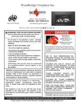
WARNING
!
HOT GLASS WILL
CAUSE BURNS.
DO NOT TOUCH GLASS
UNTIL COOLED.
NEVER ALLOW CHILDREN
TO TOUCH GLASS.
It is normal for fireplaces fabricated of steel to
give off some expansion and/or contraction noises
during the start up or cool down cycle. Similar
noises are found with your furnace heat exchanger
or car engine.
It is not unusual for gas fireplaces to give off some
odor the first time it is burned. This is due to the
manufacturing process.
It is recommended that you burn your fireplace
for at least ten (10) hours the first time you use it.
Place the fan switch in the “OFF” position during
this time.

57D0215
380IDV/490IDV Fireplace Insert
5
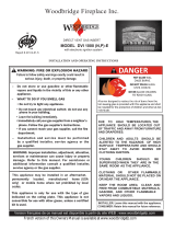
FP2621
IDV controls
• This appliance has been certified for use with
either natural or propane gas. Refer to the
appropriate data plates.
• This appliance is not for use with solid
fuels.
• The appliance is approved for bedroom or
bedsitting room installations.
• The appliance must be installed in accor-
dance with local codes if any. If none exist
use the current installation code. ANSI
Z223.1/NFPA 54 in the USA, CSA B149 in
Canada.
• The appliance must be properly connected
to a venting system.
Piezo Igniter
Figure 1 -
IDV Series Fireplace Insert
Optional
Remote
Receiver
Blower Knob
ON/OFF Switch
OFF/Pilot/ON
Knob
HI/LO Knob Gas Shut-Off
Valve
On/Off
Remote
Switch
FP2621
*Aftermarket: Completion of sale, not for purpose of resale,
from the manufacturer.
Input ratings are shown in BTU per hour and are certified
without deration for elevations up to 4,500 feet (1,370
m) above sea level.
For elevations above 4,500 feet (1,370 m) in USA,
installations must be in accordance with the current
ANSI Z223.1/NFPA 54 and/or local codes having juris-
diction.
In Canada, please consult provincial and/or local authori-
ties having jurisdiction for installations at elevations
above 4,500 feet (1,370 m).
Natural Propane (LP)
Inlet Minimum 4.5” w.c. 11.0” w.c.
Inlet Maximum 10.5” w.c. 13.0” w.c.
Manifold Pressure 3.5” w.c. 10.0” w.c.
380IDVNVC Nat. 30,500 20,500 #35
380IDVPVC LP 28,000 22,000 #53
490IDVNVC Nat. 40,000 26,500 #30
490IDVPVC LP 37,500 29,000 #50
The IDV Series gas inserts are equipped with a variable
speed output gas control.
IDV Series gas inserts operate without any elec-
trical supply. Blower must be attached to 110/120V AC.

657D0215
380IDV/490IDV Fireplace Insert
Figure 2 -
IDV Fireplace Insert Dimensions
C
D
E
M
L
G
F
B
A
B
A
H
K
I
J
570016
IDV dims
A 22C\v" (578 mm) 24C\v" (629 mm)
B 30C\zn" (767 mm) 33ZZ\zn" (856 mm)
C 27B\," (702 mm) 31Z\," (791 mm)
D 17M\zn" (443 mm) 19ZZ\zn" (500 mm)
E 10C\," (264 mm) 11Z\x" (292 mm)
F 29Z\x" (749 mm) 33" (838 mm)
G 15>\zn" (395 mm) 17Z\x" (445 mm)
H 20C\v" (527 mm) 22C\v" (578 mm)
I 21B\," (549 mm) 23ZC\zn" (605 mm)
J 22C\v" (578 mm) 24ZB\zn" (633 mm)
K 16B\zn" (414 mm) 18B\zn" (465 mm)
L 8XC\cx" (221 mm) 9XM\cx" (250 mm)
M 4Z\x" (114 mm) 5B\," (143 mm)
A
B
C
D
E
FP1622
IDV opening dims
A 28" (711 mm) 31" (787 mm)
B 18" (457 mm) 20" (508 mm)
C 21" (533 mm) 23" (584 mm)
D 21" (533 mm) 23" (533 mm)
E 16" (406 mm) 18" (457 mm)
Figure 3 -
IDV Fireplace Insert Opening Dimensions

57D0215
380IDV/490IDV Fireplace Insert
7
Read this homeowner manual thoroughly and follow all instructions carefully. Inspect all contents
for shipping damage and immediately inform your dealer if any damage is found. Do not install
any unit with damaged, incomplete, or substitute parts. Check your packing list to verify that all
listed parts have been received.
Plan for the installation of your insert. This includes determining the size of fireplace in which
unit is to be installed, length of venting to be used and finishing details, and whether any optional
accessories (i.e. wall switch, or remote control) are desired. Consult your local building code
agency to ensure compliance with local codes, including permits and inspections.
The following factors should be taken into consideration:
• This insert should have sufficient access for its safe operation and maintenance.
• The flow of combustion and ventilation air must not be obstructed.
• Minimum clearances to combustibles, such as mantels, must be maintained. Refer to Pages
8 and 9, Figures 4 and 5.
• Never obstruct the front opening of the insert.
• Do not install in the vicinity where gasoline or other flammable liquids may be stored.
• These units can be installed in a bedroom. Refer to National Fuel Gas Code ANSI Z233.1/
NFPA 54 (current edition), the Uniform Mechanical Code (current edition), and Local Building
Codes for specific installation requirements.
.
Before installing the gas fireplace insert, consider the functioning needs of the fireplace. Confirm
the size of the fireplace cavity, the design of the chimney, and the availability of the gas supply
and electricity for the insert fan.
When the unit is installed into a wood burning fireplace, the minimum distance the mantel can
be placed above the fireplace is governed by local building codes applicable to wood burning
fireplaces. Consult local authorities having jurisdiction for these clearances. The underside of
the mantel will become warm. Use only finishes which are heat resistant and do not discolor.
The dimensions shown on Pages 8 and 9,
Figures 4 and 5, are minimum clearances to
maintain when installing this heater. Follow
these instructions carefully to ensure safe
installation. Failure to follow instructions
exactly can create a fire hazard.
Maintain the following minimum clearances for service and maintenance. Refer to Pages 8
and 9.

857D0215
380IDV/490IDV Fireplace Insert
No combustibles (ie: drapes, doors) may be within, or swing within 36" of the front of the insert.
The insert must be installed on a noncombustible hearth extending a minimum of 12" from the
fireplace opening (local codes may require a larger hearth). The hearth must also extend to both
sides of the face.
Figure 4 -
Mantel Clearances
FP2623
Minimum clearances
Max.
13”
Max.
3/4”
Min.
9”
Min.
11”
13” (330 mm)
Maximum Depth
Minimum
11” (279 mm)
Minimum
8” (203 mm)
22”
(559 mm)
Minimum
10” (254 mm)
Minimum 42”
(1067 mm)
Minimum
8” (203 mm)
Minimum
8” (203 mm)
32”
(813 mm)
Minimum
12” (305 mm)
3/4" Maximum
Depth
Combustible
Facing
FP2623

57D0215
380IDV/490IDV Fireplace Insert
9
FP2624
insert placement
• The insert must be placed within a code-conforming masonry fireplace or a tested and
listed zero-clearance (UL-127, solid fuel) fireplace. Repair any fireplace damage prior to
installation.
• Because the insert uses a circulation blower, clean the fireplace, smoke shelf and chim-
ney before installing.
• This heater may be placed in a bedroom. Please be aware of the large amount of heat
this appliance produces when determining a location.
Figure 5 -
Insert Placement
For tight fits you may remove the
manifold. Refer to "Remove the
Manifold" Section
For minimum dimensions,
Refer to Page 7
The insert protrudes into
the fireplace. Refer to
Page 7 for dimensions.
The gas line should be
installed prior to insert
placement
Run the power cord
either side of the
insert along the face
Use the leveling bolts for
fireplaces with recessed
floors
Run the on/off
switch wires to the
right - behind the
surround panels
FP2624
For minimum
dimensions,
Refer to Page
7

10 57D0215
380IDV/490IDV Fireplace Insert
• The damper and grate must be removed.
•
The smoke shelf, internal baffles, screen, refractory and metal or glass doors may be removed
(if applicable)
.
• Do not remove or alter the insulation or any structured rigid frame members (metal sides, floor,
door frames, face of the fireplace, etc.).
&P
ZEROCLEARANCEREQUIREMENTS
Insulation
Damper
Smoke
Shelf
Masonry Lining or Refractory
Screen
Metal or Glass Doors
Internal
Baffles
Masonry Lining or Refractory
Grate
Figure 6 -
Metal Fireplace Zero-Clearance Requirements
Please review the following carefully.
It is normal for inserts fabricated of steel to give off some expansion and/or contraction noises during
the start up or cool down cycle. Similar noises are found with your furnace heat exchanger or car
engine.
It is not unusual for your insert to give off some odor the first time it is burned. This is due to the curing
of the paint and any undetected oil from the manufacturing process.
Burn your insert for at least six (6) hours on "HIGH" the first time you use it. Place the fan in the "OFF"
position during this time.

57D0215
380IDV/490IDV Fireplace Insert
11
Consult local building codes before beginning the instal-
lation. The installer must make sure to select the proper
vent system for installation. Before installing vent kit,
the installer must read this insert manual and vent kit
instructions.
Only a qualified installer/service person should install
venting system. The installer must follow these safety
rules:
• Wear gloves and safety glasses for protection.
• Use extreme caution when using ladders or when
on rooftops.
• Be aware of electrical wiring locations in walls and
ceiling.
The following actions will void the warranty on your vent-
ing system:
• Installation of any damaged venting component.
• Unauthorized modification of the venting system.
• Installation of any component part not manufac-
tured or approved by MHSC.
• Installation other than permitted by these instruc-
tions.
Figure 6
• The exhaust vent must reline the entire length of
chimney and terminate above chimney top.
• Vent must meet all vent manufacturer's requirements
when installed.
• Make sure you have the following before installing
unit:
• 3" and 3" UL 1777 Listed gas liner for air inlet and
exhaust.
• Vertical termination kit (AI31TK33A)
• 4" and 3" UL 1777 Listed gas liner for air inlet and
exhaust.
• Vertical termination kit (AI42TK43A)
FP2625
typical venting
Exhaust
Inlet
Maximum 12"
(305 mm) Offset at
Base of Insert
Maximum
Height
40' (12.9 m)
Minimum
Height
10' (3 m)
FP2625
Figure 7 -
Venting Unit

12 57D0215
380IDV/490IDV Fireplace Insert
High-Temp
Silicone
High-Temp
Silicone
FP2626
connect exhaust pipe
This heater has been tested at altitudes ranging from sea level to 4,500 feet (1,370 m). In this
testing, heater with standard orifice burns correctly with just an air shutter adjustment. If you
need to resize orifice for use at high altitude, contact your dealer.
380 Series - 3" and 3"
UL 1777 Gas Liner
490 Series - 4" and 3"
UL 1777 Gas LIner
Apply high-temperature silicone to
lines on both ends and secure with
two (2) screws
Termination Kit
380 Series - AI3TK33A
490 Series - AI42TK43A
Figure 8 -
Connecting Vent Pipe to Heater
FP2626
Inlet
Exhaust
(Centered on unit)

57D0215
380IDV/490IDV Fireplace Insert
13
You may use either reline configuration with a masonry
or zero-clearance fireplace.
FP2627
inlet exhaust reline
Exhaust
Inlet
Recommended block-off
plate (noncombustible
metal). Prevents odors from
chimney entering room.
UL 127 Solid
Fuel Z.C Fire-
box
Figure 9 -
Inlet and Exhaust Reline
FP2627
3" (76 mm) or 4" (102 mm) Exhaust
UL 1777 Gas Liner 3" (75 mm) Inlet
Termination Kits:
380 Series: AI31TK33A
490 Series: AI42TK43A

14 57D0215
380IDV/490IDV Fireplace Insert
The manifold is shipped attached to insert. It may be
removed to allow tight installation. Manifold may be loos-
ened and rotated for desired
pipe location.
1. Remove brick liner and
baffle.
2. Remove manifold. Place
manifold in fireplace.
3. Route flex vent through chim-
ney from above. Figure 10.
Leave an extra 3" (914 mm)
at the top.
FP2629
flex vent
Flex
Vent
Chimney
Manifold
Bracket
Nut
FP2629
Figure 10 -
Place Manifold into Fireplace
FP2630
attach flex vent
Extra 3"
Chimney
Flex
Vent
Manifold
FP2630
Figure 11 -
Attach Flex Vent to Manifold
4. Attach flex vent to
manifold. Figure 11.
Seal with silicone
and attach with
screws.
FP2631
pull excess vent
Excess
Flex
Vent
Chimney
Slack in
Flex Vent
Manifold
FP2632
Figure 12 -
Pull on Excess Flex Vent
5.Place manifold in
an upright posi-
tion. Pull on excess
vent. Figure 12.
Temporarily attach
flex vent to top of
chimney. Leave
some extra slack
in flex vent.
FP2632
place insert
Vent
Termination
Chimney
Excess Slack
Take out of Flex
Vent
Manifold
Bracket
Nut
FP2632
Figure 13 -
Slide Insert into Place
Insert
6. Slide insert into place.
Guide the manifold
over the insert until it
is fully in place. Figure
13
7. Remove any slack from
flex vent. Attach mani-
fold to insert. Figure
13
8. Remove any excess
slack in flex line. Attach
vent termination.
Figure 13
9. Replace baffle and
brick liner.

57D0215
380IDV/490IDV Fireplace Insert
15
Make sure you have the items listed below before installing appliance.
• External regulator (supplied by installer) • Piping (check local codes) • Test gauge connection*
• Sealant (resistant to propane/LP gas) • Sediment trap (optional but recommended)
• Tee joint • Pipe wrench
• approved flexible gas line with gas connector (if allowed by local codes — not provided)
* A CSA design-certified equipment shutoff valve with 1/8" NPT tap is an acceptable alternative to test
gauge connection. Purchase the CSA design-certified equipment shutoff valve from your dealer.
For propane/LP connections only, the installer must supply an external regulator. The external regulator will
reduce incoming gas pressure. You must reduce incoming gas pressure to between 11 and 13 inches of wa-
ter. If you do not reduce incoming gas pressure, burner system regulator damage could occur. Install external
regulator with the vent pointing down as shown in Figure 14. Pointing the vent down protects it from freezing
rain or sleet.
&0
EXTERNALREGULATOR
External
Regual-
tor
Vent
Pointing
Down
100 gal. (min.
Propane/LP
Supply Tank
FP1930
Figure 14 -
External Regulator with Vent Pointing Down
(Propane/LP Only)
Use proper gas type for the fireplace you are installing. If you have conflicting gas type, do not install
fireplace. See dealer where you purchased the fireplace for proper fireplace according to your gas
type.
When using copper or flex connectors use only fittings
approved for gas connections. The gas control inlet is
3/8" NPT.

16 57D0215
380IDV/490IDV Fireplace Insert
Figure 15
A listed manual shutoff is factory installed upstream of appliance. Union tee and plugged 1/8"
NPT pressure tapping point should be installed upstream of the appliance. Figure 15
The main gas valve is for turning on or shutting off the gas to the insert.
Check your building codes for any special requirements for
locating equipment shutoff valve to inserts.
Apply pipe joint sealant lightly to threads. This will prevent
excess sealant from going into pipe. Excess sealant in pipe
could result in clogged burner system valves.
We recommend that you install a sediment trap/drip leg in
supply line as shown in Figure 15. Locate sediment trap/drip
leg where it is within reach for cleaning. Install in piping system between fuel supply and burner
system. Locate sediment trap/drip leg where trapped matter is not likely to freeze. A sediment
trap traps moisture and contaminants. This keeps them from going into the burner system
gas controls. If sediment trap/drip leg is not installed or is installed wrong, burner system may
not run properly.
NOTE : The gas line connection may be made using 1/2" rigid tubing or an approved
flex connector. Since some municipalities have additional local codes it is always best
to consult your local authorities and the current edition of the National Fuel Gas Code
ANSI.Z223.1, NFPA54. In Canada CSA-B149 (1 or 2) Installation Code.
3" Minimum
FP1931
gas connection
9/08
Approved Flexible
Gas Line Supplied
with Appliance
Tee Joint
Pipe Nipple
Cap
From Gas Meter
(4.5" w.c. to 10.5" w.c. Pressure)
From External Regulator
(11" w.c. to 13" w.c. Pressure)
Figure 15 -
Gas Connection

57D0215
380IDV/490IDV Fireplace Insert
17
1. Check gas type. The gas supply must be the same as stated on the appliance’s rating decal. If
the gas supply is different from the fireplace, Do not install the appliance. Contact your
dealer immediately.
2. Install and attach flex line provided on this appliance to 1/2" gas line.
3. After completing gas line connection, purge air from gas line and test all gas joints from the
gas meter to the fireplace for leaks. Use a soap and water solution or a gas sniffer.
4. To adjust flame height, turn HI/LO knob to HI to
get maximum pressure to burner. Turn HI/LO
knob to LO to get minimum pressure.
5. To check gas pressures at valve, turn captured
screw counter clockwise 2 or 3 turns and then
place tubing to pressure gauge over test point.
Turn unit to high. Figure 16. After taking pressure
reading, be sure and turn captured screw clock-
wise firmly to reseal. Do not over torque. Check
test points for gas leaks with a soap and water
solution or an electronic gas leak detector.
FP1932
valve regulator with knobs
Pressure
Test "IN"
Pressure Test
"OUT"
HI/LO Knob Pilot Adjustment Screw
FP1932
Figure 16 -
Gas Pressure Check at Gas Valve

18 57D0215
380IDV/490IDV Fireplace Insert
A remote wall switch and up to fifteen (15) feet of 18 Ga. wire may be used with this appliance. At-
tach the wall switch in a junction box at the desired location on the wall. Figure 17
This insert will work without any electrical supply. Electricity is only needed to operate blower.
Verify proper operation after servicing.
National Electrical Code ANSI/NFPA 70 (latest edition)Canadian Electrical Code, CSA
C22.1
PILOT HI
LO
ON
OFF
FP1933
wall switch wiring
Figure 17 -
Wiring Diagram for Wall Switch
Sparker
Thermocouple
Piezo Igniter
Thermopile
Pilot Assembly
Switch
Millivolt
Valve
TH
TP
TH/TP
ON OFF
Optional 15'
Wall Switch
Optional
Remote Control
ON
OFF
ON
OFF

57D0215
380IDV/490IDV Fireplace Insert
19
- This unit is supplied with seven (7) ceramic fiber logs. Do not handle these logs with
your bare hands. After handling
the logs, wash your hands gently with soap and water to remove any traces of fibers.
1. Open front door of firebox.
2. Break up rock wool (ember material) into dime-sized pieces. Place evenly as shown. Do not exceed
1" layer. Figure 18
LG765
place rockwool
Rockwool
Areas
LG765
LG766
rockwool
LG766
Figure 18 -
Rockwool Placement
LG767
Rear log #1
Rear Log
#1
LG767
Figure 19
3. Carefully remove the seven (7) logs
from wrapping.
4. Place rear log #1 against back of
firebox. Figure 19

20 57D0215
380IDV/490IDV Fireplace Insert
5. Align holes in the bottom of the left base
log #2 with two (2) pins on the left side of
insert. Install left base log. Figure 20
LG766
rockwool
Left Front Log
#2
LG768
Figure 20
6. Align holes in bottom of right base log #3
with two (2) to the right of rear log. Figure
21
7. Align hole in bottom left center log #4 with
pin on burner. Figure 22
LG769
place right base log 3
Right Base Log
#3
LG769
Figure 21
LG770
place left ctr log 4
Left Center Log
#4
LG770
Figure 22
/