Safety Instructions:
• All installation commissioning, repair, and service work to this product must be
undertaken by suitably qualied and trained personnel.
• The unit must be earthed.
• Disconnect the power before working on the unit.
• On 230 VAC models, a readily accessible disconnect protection device must be
incorporated in the mains wiring.
• On all models, the power supply MUST have short circuit protection and over
current protection installed at the power source. Typically, this will be a 5Amp
Magnetic Circuit Breaker for AC models and a fuse for DC models.
• This product must be installed in an enclosure.
• Always suspend trafc through the barrier area during installation and test as this
may result in unexpected operation of the barrier.
• There are no serviceable parts or internal settings inside the product. The product
warranty will be voided if the cover has been removed or if there is any tampering
with the product.
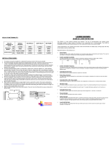
Electrical Connections:
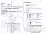
• Refer to the side-label on the side of the unit to verify the corresponding pin-out
functions for both the 11 Pin Connector and DIN Rail housing variants of the LC20
the pin-outs may vary from model to model.
• Before connecting the detector to the power supply, ensure that you have the
correct power supply for the model you are using:
- LC20 - 1 - RB/DR 230VAC = 230VAC
- LC20 - 1 - RB/DR 12-24VAC/DC = 12V to 24V AC/DC
Front Panel Indications:
The front panel indicators consist of a Red Power / Communicator LED and one Green
Channel LED.
Description Function
Power LED
This red LED is on to indicate the unit is powered and functional
This red LED is also used as a communications interface with the LC20DT
diagnostic device to obtain information from the unit.
Channel LED
This green LED indicated the current status of the detector. It can indicate
four possible conditions namely, tuning, idle, detect, or fault.
• Tuning condition- the detector is currently tuning the loop - green LED
ashes at a rate of 2Hz
• Idle condition- no vehicle is detected - green LED is off.
• Detect condition- a vehicle is detected passing over the loop - the green
LED is on.
• Fault condition - the detector is unable to tune to the loop as it is either
out of operational conditions such as low signal strength or frequency
out of range or there exists a fault on the loop such as a short circuit or
an open circuit- the green LED ashes at a rate of 2Hz.
If the fault is self-healing the detector will continue to operate but the green
LED will ash at a rate of 1Hz.
DIP Switch Selections:
Presence Time (Switch 10) – The presence time setting determines how the
detector will track a detect. There are two selection options available, namely
permanent presence and limited presence. The permanent presence mode setting
will maintain the presence of a vehicle over the loop by continuously compensating for
all environmental changes. The limited presence mode setting will limit the presence
of a vehicle over the loop and the presence time is related to the size of the detect.
Typically, a 1% ∆L/L will timeout after approximately 1 hour.
• Pulse on Detect or Undetect (Switch 9) - The pulse relay can be set to pulse
on detect, as a vehicle enters the loop, or pulse on undetect, as the vehicle
exits the loop.
• Pulse width (Switch 8) – The pulse width of the pulse relay can be set to either
150ms or 250ms.
• Automatic Frequency Selection (A.F.S.) (Switch 7) - This setting allows
the detector to briey evaluate all ve frequency bands and select the best
operating frequency available. The tuning time with AFS switched on can
range between 5 and 20 seconds. With AFS switched off, the frequency can be
selected manually.
• Fail-safe or Fail-secure (Switch 6) - The relay output operation of the
presence relay can be switched between fail-safe and fail-secure.
• Automatic Sensitivity Boost (A.B.S.) (Switch 5) – ASB is a mode which
alters the undetect level of the detector. ASB causes the sensitivity level to
be boosted to a maximum on detection of a vehicle, irrespective of the current
sensitivity level maintained at this level during the entire presence of the
vehicle over the loop. When the vehicle leaves the loop and the detection is
lost, the sensitivity level reverts to the pre-selected level. This is typically used
for vehicles with high beds, or vehicles towing trailers, where it is important to
maintain the detect over the entire length of the vehicle.
• Sensitivity (Switches 3&4) – The sensitivity of the detector allows the detector
to be selective as to the change of inductance necessary to produce a detect.
There are four possible sensitivity selection options, High (0.01% ∆L/L),
Medium-High (0.02% ∆L/L), Medium-Low (0.05% ∆L/L), and Low (0.1% ∆L/L).
• Manual Frequency Selection (Switches 1 & 2) - **AFS must be turned to
the OFF position to select the frequency manually. There are four possible
frequency selection options, High, Medium-High, Medium-Low and Low.
Relay Outputs:
The LC20-1 has two relay outputs, with one relay set to output presence on detect
and the other to output a pulse on detect or undetect. The Pulse relay automatically
operates in fail secure mode, while the presence output relay can be set to operate in
fail safe or fail secure mode.
Presence Relay Programming
Fail Secure Fail Secure
Relay
N/C N/O N/C N/O
Undetect Open Closed Closed Open
Detect Closed Open Open Closed
Fault Open Closed Open Closed
Power Off Open Closed Open Closed
Pulse Relay
N/O N/C
Idle Open Closed
On Event Closed Open
Fault Open Closed
Power Off Open Closed
Pushbutton:
The pushbutton is a multipurpose button which can be used to initiate a retune or can
be used to either enable or disable the power fail feature, depending on how long the
pushbutton is held in.
Description Hold Function
Reset 3 sec This will initiate a detector retune.
Power Fail 10 sec
Hold for 10s to determine the state of Powerfail. If the
LEDs are ON, Powerfail is ON. If the LEDs are OFF,
Powerfail is OFF
Power Fail Toggle 30 sec
Holding for 30s will determine the Powerfail status. The
state of the Powerfail is known after holding for 10s. After
30s the LEDs turn OFF, Powerfail is now OFF. If after 30s
the LEDs turn on, Powerfail is now ON
Automatic Frequency Selection:
The Automatic Frequency Selection (A.F.S) feature enables the unit to briey evaluate
all ve frequency bands and select the best operating frequency available. It weighs
up each selection based om where the frequency is located within the operational
range, the signal strength, and the level of detected noise. AFS allows the detector to
evaluate all the frequency selections.
Due to the increased processing required, AFS takes longer to tune than when it is
deactivated. The tune time with AFS on can range from 5 to 20 seconds. Id after
this period of time, the detector still has not tuned, it is also possible that none of
the frequency selections are suitable for the loop. If this occurs, manual frequency
selection should be used. Due to the sporadic nature of noise, the channel may seem
quiet during the evaluation but still suffer from cross-talk.
Power Fail:
The Power fail feature allows the unit to remember its operating conditions and
detect status in the event of power being removed. When power is restored, the unit
continues operating from saved conditions and status. This is designed specically
for fail safe situations to retain the output state and prevent a glitch on the outputs for
power failure. As such, when the power is restored the detector will not retune but will
instead return to the detect state prior to the power failure. If a vehicle was on the loop
during the power failure, it will remain detected when the power is restored. Thus, it
prevents the tuning out of a vehicle over the loop during a power failure.
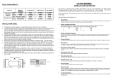
Loop Installation Guide:
Optimum functioning of the detector is largely dependent on factors associated with
the inductive sensor loop it is connected to. These factors include choice of material,
loop conguration and correct installation practice. A successful inductive loop vehicle
detection system can be achieved with the following constraints in mind and strictly
following the installation instructions. The detector must be installed in a convenient
weatherproof location as close as possible to the loop.
POWER
CH1
RESET
307FP0102-00
LC20 - 1 INSTALLATION GUIDE
TDOCT-6305_ENG


 1
1
 2
2
Pepperl+Fuchs LC20-2-RB 12-24VAC/DC Installation guide
Pepperl+Fuchs LC20-1-RB 230VAC User manual
Pepperl+Fuchs LC20-DT User manual
Pepperl+Fuchs LC10-1-D 115 VAC Owner's manual
Pepperl+Fuchs LC10-2-D 24VDC Operating instructions
Pepperl+Fuchs LHC-M51 Operating instructions
Pepperl+Fuchs ENT-DC-30 Technical Manual
 Nortech PD271 User manual
 Procon LD201 Installation guide
EMX ULT-II User manual
Elsema MD2010 User manual
 SEAV LD100 User guide
 SensAble Sensors ULD4669/13F Owner's manual
![Eberle DesignDeflectometer Inductive Loop Monitor [LMD602, LMD602T, LMD604,LMD604T]](//vs1.manuzoid.com/store/data/001476625_2-352a61b560d4fc181793a55d495056b5-160x210.png) Eberle Design Deflectometer Inductive Loop Monitor [LMD602, LMD602T, LMD604,LMD604T] User manual
Eberle Design Deflectometer Inductive Loop Monitor [LMD602, LMD602T, LMD604,LMD604T] User manual
 DIABLO DSP-19 User manual
GTO LOOPDT1 Reference guide
BEA MATRIX FAMILY User guide


![Eberle DesignDeflectometer Inductive Loop Monitor [LMD602, LMD602T, LMD604,LMD604T]](http://vs1.manuzoid.com/store/data/001476625_2-352a61b560d4fc181793a55d495056b5-160x210.png)
