Page is loading ...

Owner’s Manual
Brave 3” Trash Pump (GX270)
WARNING
Read and understand all instructions.
Failure to follow all instructions may result in serious injury or property damage.
WARNING: Wear appropriate protective gear. This list includes, but is not limited to:
-safety glasses, protective boots with slip resistant soles, gloves, hearing protection.
• WARNING: Keep guards in place and in working order. Never operate the product without the guards in place.
• WARNING: LETHAL EXHAUST GAS! An internal combustion engine discharges carbon monoxide, which is a
poisonous and odorless invisible gas. Death or serious illness may result if inhaled. Operate only in an area with
good ventilation.
• DANGER: Do not smoke when refueling.
• WARNING: Do not use pump in explosive atmosphere.
• WARNING: Do not pump volatile or ammable liquids such as gasoline, fuel oil, kerosene, etc.
• CAUTION: Do not attempt to operate pump, if any parts are missing or damaged.
• CAUTION: For proper handling techniques and cautions when pumping certain chemicals, contact your chemical
supplier or local agencies (re dept etc)
• CAUTION: The engine is hot enough to cause injury, do not touch the exterior of the engine, especially the muer
and surrounding area.
• WARNING: Even though this unit will operate with minimal supervision, it should not be left operating by itself.
Depending on the application and area unit is operating (high trac, people in area, etc.) will dictate the necessity
of having someone watching over the unit.
• CAUTION: Do not allow pump to be located in freezing or colder weather. Damage to pump will result.
• CAUTION: Do not run pump dry, as permanent damage to the mechanical seal will result.
STOP!
ADD OIL TO ENGINE BEFORE USING: Engine is shipped without oil. DO NOT start engine without rst adding oil.
INSPECT COMPONENTS: Closely inspect to make sure no components are missing or damaged.
Any Questions, Comments, Problems or Parts Orders
Call Brave Support 1-800-350-8739
ITEM NUMBER(S): BRP550TP3
MANUAL SERIAL TAG HERE
MBRP550TP3

Specications Information and Repair Parts Manual BRP550TP3
800-350-8739 2 MBRP550TP Rev A | 3/2020
Please read and save this Owner’s Manual. Read this manual carefully before attempting to operate or maintain this pump. Protect yourself and others by ob-
serving all safety information. Failure to comply with the safety instructions accompanying this product could result in personal injury and/or property damage!
Retain instructions for future reference. Brave reserves the right to discontinue any model or change specications at any time without incurring any obligation.
Periodic maintenance and inspection is required on all pumps to ensure proper operation. Unit must be clear of debris and sediment. Inspect for leaks and loose
bolts. Failure to do so voids warranty.
BRP550TP3
SPECIFICATIONS
Standard units are constructed of cast aluminum with cast iron impeller, cast
iron volute, and cast iron suction and discharge manifolds. Standard shaft
seals for 3S pumps are Viton with silicon carbide wear faces. All models
feature EPDM/EPR O-rings, Flapper Valve & Gaskets.
IMPORTANT: Not for use with petroleum based liquids.
UNPACKING
1. Remove pump from packaging materials.
2. Package should include: pump/engine mounted in roll frame, strainer,
general/safety manual, specication/parts manual, engine manual.
3. Make sure all components are accounted for before discarding packaging
material.
4. Inspect all components for damage.
5. No assembly is required for standard engine driven pumps.
PREPARING UNIT FOR OPERATION
Placing Pump
1. Always place the pump as close to the liquid source as possible. Priming
eciency and pump output will be reduced if a long (>25 ft.) suction line
is used. Keep all lines as short and straight as possible. Avoid any sharp
bends. Suction line cannot have loops or high spots, hose must have a
gradual slope up to pump.
2. Pump/engine must be located on a solid level surface.
Connecting Hose or Piping
1. All suction hose/piping connection must be air tight. Pump will not prime if
there are any air leaks in the suction line or connections.
2. Use only non-collapsible hose or pipe on the suction. If collapsible hose
is used on the discharge, the end of discharge line is submerged in liquid,
or a check valve is placed in the discharge line, a means of venting air out
of the pump during the priming cycle must be employed.
3. Always use a suction strainer to keep large debris out of the pump. Position
strainer well below liquid surface and on a bed of rocks or other suitable
surface. If possible tie strainer up so it is suspended o pit bottom. As a
last resort tie the strainer in a large submerged bucket if bottom of water
source is too soft or muddy.
Before Starting Engine
1. Fill engine crankcase with oil. Follow engine manufacturer
recommendations for service classication and viscosity of oil as detailed
in engine manual.
2. Fill fuel tank with clean, fresh, fuel. Follow engine manufacturer’s
guidelines as listed in engine manual.
3. Always ll pump with liquid through the priming port located on top of the
discharge manifold or pump casing before starting engine. Remember the
pump is self-priming only when the pump is lled with liquid.
Operation
1. Make certain pump is lled with liquid before starting engine. Failure to do
so will result in damage to the mechanical shaft seal. Never run pump dry
DO NOT USE PUMP IN EXPLOSIVE ATMOSPHERE. DO NOT PUMP
VOLATILE OR FLAMMABLE LIQUIDS.
2. Follow engine manufacturer’s starting procedure. Run engine at full speed
during priming. After pump has primed speed may be reduced to regulate
pump output.
3. Pump will self-prime to a vertical height of 10’ in less than one minute,
20’ in 2 minutes, 25’ may take up to 4 minutes. If pump doesn’t prime:
Check for air leaks, move pump closer to liquid, shorten suction line,
remove loops and high spots from suction line, rell pump with liquid, see
troubleshooting guide in this manual.
4. Always allow engine to cool before refueling.
After Pump is Shut Down
1. Always ush the pump out at the end of operation if the liquid being
pumped may leave a solid or sticky residue inside of pump, or if a buildup
of sediment inside the pump is expected.
2. Always drain pump completely of liquid if there is a chance of freezing.
Storing Pump
1. When pump is out of service for an extended period of time, completely
drain liquid from casing, store pump in a dry, protected, well-ventilated
area.
2. Add fuel stabilizer to engine fuel tank or drain fuel from tank. Turn fuel tank
valve to o position.
DESCRIPTION
Brave engine driven pumps are commercial duty, centrifugal, self-priming (to 25 ft. vertical lift after initially lling casing with liquid), portable units. Pumps are
equipped with industry standard mechanical shaft seals. Iron suction and discharge manifolds are standard male NPT threads for direct connection to swivel
hose tting with gasket, or standard NPT pipe ttings. Discharge manifold can be rotated 180˚ (in 90˚ increments); left side discharge, front discharge or right
side discharge. Pump components will handle liquids with a temperature range of 40˚ to 180˚F (4˚ to 82˚ C). Pump only nonammable liquids compatible with
pump component materials. Standard pumps are close coupled to internal combustion engines manufactured by Honda. All engines meet current EPA emissions
requirements, per the engine manufacturer.

Specications Information and Repair Parts Manual BRP550TP3
800-350-8739 3 MBRP550TP Rev A | 3/2020
COMPLETE PUMP ASSEMBLY PROCEDURE
Reference Repair/Replacement Part Exploded View and Lists
NOTE: Do not use petroleum based lubricants with EPDM rubber seal parts
and O-rings. Petroleum based products will damage EPDM components.
NOTE: Apply a small amount of anti-seize lubricant to internal threads of stub
shaft. If petroleum based anti-seize lubricant is used do not allow it to contact
EPDM components.
Install Adapter
1. Lay engine (Ref. No. B6) down on recoil starter with PTO shaft straight up.
2. Locate adapter (Ref. No. B3) on engine. Fasten with screws (Ref. No. B4).
Tighten screws to 12 ft-lb torque.
Install Seal Plate & Bracket
1. Lay seal plate (Ref. No. B1) down on a stable surface with machined face
up.
2. Lubricate rubber cup or o-ring of shaft seal seat (Ref. No. A11) with soapy
water.
3. Locate seal seat in seal plate bore with nished lap surface of seat up.
Press seal seat rmly into seal plate until fully seated.
4. Locate seal plate onto adapter. Align seal plate outside diameter with
adapter diameter.
5. Install o-ring (Ref. No. D2) into bore of bracket (Ref. No. A1).
6. Install bracket onto adapter. Align bracket feet with engine mounting
surface.
7. Install screws (Ref. No. B5). Tighten screws to 12 ft-lb torque.
Install Studs into Bracket
1. Install stud (Ref. No. A2), the longer stud, into threaded hole at 7:30 (lower
left) position in bracket. Use a liquid thread locker similar to Loctite.
2. Install stud (Ref. No. A3), the shorter stud, into threaded hole at 2:30
(upper right) position in bracket. Use a liquid thread locker similar to
Loctite.
3. Secure studs in position with a lock nut (Ref. No. A4).
Install Shaft Sleeve
1. Install shaft sleeve (Ref. No. A9) on engine shaft. Locate chamfered id
towards engine. Make certain end of sleeve mates against shaft shoulder.
2. Lubricate inside diameter of rubber portion of shaft seal head (Ref. No.
A10) with soapy water. Locate seal head onto shaft sleeve with seal head
rotating ring face towards seal seat installed in seal plate. Slide seal head
onto shaft sleeve until seal faces touch.
3. Alternate procedure: mark height of seal seat face on the shaft sleeve with
a pencil or marker. Remove shaft sleeve from shaft. Slide seal head onto
shaft sleeve until rotating face is at marked height. Re-install shaft sleeve
with seal head onto engine shaft.
4. Install seal head spring if it was removed.
Install Impeller (3S) Semi-Open Impeller
1. Install shims (Ref. No. A8) onto engine shaft.
2. Install impeller (Ref. No. A7) onto engine shaft. Tighten clockwise until
fully seated against shims and shaft sleeve.
3. Install volute (Ref. No. A5) onto studs in bracket. Slide on, locate volute
in bracket machined locating diameter. Hold volute against the bracket
Disable engine ignition so engine cannot start when engine shaft is
rotated.
4. Rotate engine shaft. If impeller installed on engine shaft spins freely add
shims until it scraps against volute wear face. If impeller scrapes volute
wear face or if shaft will not turn because impeller is tight against volute
wear face proceed to next step.
5. Remove a (one) shim. Try to rotate engine shaft again. Repeat process of
removing one shim at a time and trying to rotate engine shaft until impeller
is clear and engine shaft turns with no interference.
6. Clearance between the impeller face and the volute face should be set
to 0.01” to 0.03”.
7. Install hex nuts (Ref. No. A6) fastening volute to bracket. Tighten nuts to
50 in-lb torque.
Install Casing (All Pumps)
1. Install check valve (Ref. No. D1) on end of volute. Orient hinge of apper
at the top 12:00 position.
2. Install #378 o-ring (Ref. No. D3) onto casing (Ref. No. C1).
3. Install six screws (Ref. No. C2) through casing ears. Fix screws in position
by sliding a #109 o-ring (Ref. No. C3) over each screw into casing ear
back bore.
4. Install a #117 o-ring (Ref. No. D4) onto a plug (Ref. No. D5). Lubricate
o-ring with soapy water. Install plug into casing drain port.
5. Position casing onto bracket, locate casing o-ring nose into bracket front
bore. Slide casing into bore until it bottoms. Tighten all six hex screws
in a diagonal pattern fastening casing to bracket. Tighten screws to 100
in-lb torque.
6. Check operation of check valve. Check valve must swing freely.
Install Suction Flange
1. Position a ange gasket (Ref. No. D6) on the casing suction ange.
2. Position suction ange (Ref. No. C4) on ange gasket. Install four screws
(Ref. No. C5) tighten to 100 in-lb torque. Alternate tightening screws in a
cross pattern to reduce the chance of crushing the ange gasket.
Install Discharge Manifold
1. Position a ange gasket (Ref. No. D6) on the casing discharge ange.
2. Position discharge manifold (Ref. No. C6) on ange gasket. Install four
screws (Ref. No. C7) tighten to 100 in-lb torque. Alternate tightening
screws in a cross pattern to reduce the chance of crushing the ange
gasket.
3. Install a #117 o-ring (Ref. No. D4) onto a plug (Ref. No. D5). Lubricate
o-ring with soapy water. Install plug into discharge manifold ll port.
REPAIR AND MAINTENANCE INSTRUCTIONS
Shaft Seal Replacement
1. Loosen six screws (Ref. No. C2) until they disengage the bracket (Ref.
No. A1). Remove casing (Ref. No. C1) from bracket.
2. Remove hex nuts (Ref. No. A6). Remove volute (Ref. No. A5).
3. Remove impeller (Ref. No. A7). Impeller unthreads counter-clockwise.
4. Remove impeller shims (Ref. No. A8) if so equipped (3S pumps).
5. Remove shaft sleeve (Ref. No. A9)/seal head (Ref. No. A10) assembly.
Remove seal head from shaft sleeve. Discard old seal. Thoroughly clean
shaft sleeve. If it is damaged or the old elastomer can’t be removed
replace with a new shaft sleeve.
6. Loosen bracket foot screws (Ref. No. E5). Remove screws (Ref. No. B5).
Remove bracket (Ref. No. A1)
7. Remove seal plate (Ref. No. B1).
8. Pry old seal seat (Ref. No. A11) from seal plate. Discard old seal.
Thoroughly clean the seal seat bore.
9. Replace any worn or damaged o-rings.
10. Rebuild pump with a new shaft seal. Follow complete pump assembly
BRP550TP3

Specications Information and Repair Parts Manual BRP550TP3
800-350-8739 4 MBRP550TP Rev A | 3/2020
BRP550TP3
procedure.
Cleaning Pump
1. Remove casing assembly from bracket.
2. Clean-out any debris.
3. Remove hex nuts fastening volute to bracket. Remove volute.
4. Clean-out any debris from volute.
5. Clean any debris from impeller vanes.
6. Remove impeller. Impeller unthreads counterclockwise. Run a heavy wire
through impeller passages to dislodge any accumulated debris.
7. Reassemble the pump.
Periodic Maintenance
1. Clean outside of pump and engine to remove accumulated dirt, oil and
grime.
2. Maintain engine according to engine manufacturer’s recommendations.
3. It is recommended that a replacement shaft seal and seal kit be kept on
hand at all times.
4. Check for leaks during pump operation. Leaks may occur at shaft seal,
casing to bracket connection, suction and discharge manifold connections,
and through pump casing and bracket. Investigate and repair any leaks
immediately.
NOTE: Engine failure due to water intrusion into crankcase caused by a
leaking seal will not be covered by engine or pump warranty.
5. Mechanical shaft seals are a wear item and require periodic replacement.
Seal life is dependent on many factors including liquid pumped, sediment
type, operating point, and suction conditions.
6. Inspect for loose fasteners. Tighten any loose fasteners immediately.

Specications Information and Repair Parts Manual BRP550TP3
800-350-8739 5 MBRP550TP Rev A | 3/2020
BRP550TP3
Problem Possible Cause(s) Corrective Action
Pump fails to prime 1 Pump not lled with liquid 1Add liquid to pump through priming port
2 Air leak at suction line connection 2 Add sealant to connection
3 Worn suction connection gasket 3 Replace suction gasket
4 Leaking suction line 4 Inspect, repair or replace suction line
5 Engine speed too low 5 Run engine at maximum speed
6 Worn or broken volute or impeller 6 Replace parts as required
7 Leaking/worn mechanical shaft seal 7 Replace mechanical shaft seal
8 Clogged suction strainer/line 8 Clean strainer and suction line
9 Suction lift too great (25 ft. max) 9 Reduce lift
10 Suction line too long 10 Reduce length to under 30 feet
11 Pump is air locked 11 Vent pump discharge through priming port
Priming remedies that will NOT work:
Holding suction line out of liquid source and forcing liquid into end while pump is running.
Pinching o the discharge line to “build up pressure”.
Holding hand against end of suction line or pump suction port to “feel” for suction.
Follow above priming troubleshooting guide.
If pump still will not prime after all corrective action is exhausted, check pump priming capacity by:
1. Install a vacuum gauge on capped suction port. Gauge to suction port connection must be
100% air tight.
2. Fill pump casing completely with water.
3. Run pump at full speed, some water will be thrown out of discharge.
4. Vacuum gauge should register 18-22 inches of mercury within a minute or so.
a. If vacuum registers below 18 in of hg check gauge to pump connection for air leaks,
inspect/replace volute, impeller and shaft seal as required.
b. If vacuum gauge value is within range pump is working correctly. The problem is not
the pump.
Reduced capacity or discharge
pressure
1. Clogged strainer or lines 1. Clean strainer, suction and discharge lines
2. High friction loss in line 2. Remove kinks and elbows, reduce length
3. Discharge head too high 3. Lower end of discharge line, remove
nozzles
4. Engine speed too low 4. Increase engine speed
5. Drop in engine output 5. Repair engine
6. Clogged impeller 6. Remove clog
7. Worn/damaged impeller or volute 7. Replace parts as required
Pump will not work/engine will not
turn over
1. Clogged pump 1. Remove clog between impeller and volute
2. Pump parts rusted together 2. Disassemble pump, free parts
3. Damaged impeller or volute 3. Replace volute or impeller
4. Engine seized 4. Remove pump from engine, check engine
itself
Pump will not work/engine runs 1. Impeller stripped/key sheared 1. Disassemble pump, replace parts/engine
2. Pump impeller/volute clogged 2. Clean pump
3. Will not prime 3. See Priming troubleshooting section
4. Insucient liquid supply 4. Increase liquid supply

Specications Information and Repair Parts Manual BRP550TP3
800-350-8739 6 MBRP550TP Rev A | 3/2020
For Repair Parts contact dealer where pump was purchased.
Please provide following information:
-Model Number
-Serial Number (if any)
Part description and number as shown in parts list
Specications Information and Repair Parts Manual 3P9X & 3S9X
3S9X-250-00 5 2/2015
For Repair Parts contact dealer where pump was purchased.
Please provide following information:
-Model Number
-Serial Number (if any)
Part description and number as shown in parts list
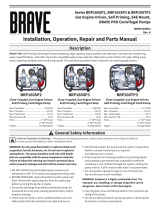
Figure 1 - Repair Parts Illustrations
IPT Series 3P9X & 3S9X Pumps
Figure 1 - Repair Parts Illustrations
BRP550TP3

Specications Information and Repair Parts Manual BRP550TP3
800-350-8739 7 MBRP550TP Rev A | 3/2020
Ref Engine Honda GX270
No. Description BRP550TP3 Qty
A1 Bracket Kit 3S9X-030-96 1
(includes Ref. Nos. A1, A2, A3 ,
A4 & B5)
A2 1/4-20x2.5" Stud Incl. w/Ref. A1 1
A3 1/4-20x2.5” Stud Incl. w/Ref. A1 1
A4 1/4-20 Jam Nut Incl. w/Ref. A1 2
A5 Volute Kit 3S9X-150-95 1
(includes Ref. Nos. A5 & A6)
A6 1/4-20 Hex Nut Incl. w/Ref. A5 2
A7 Impeller Kit 3S9X-011-95 1
(includes Ref. Nos. A7, A8 & A9)
A8 Shim Incl. w/Ref. A7 1
A9 Shaft Sleeve Incl. w/Ref. A7 1
A10 & A11 Shaft Seal Kit 1646-323-00 1
B1 Seal Plate Kit 3S9X-020-95 1
(includes Ref. Nos. B1 & B2)
B2 1/8" NPT Plug Incl. w/Ref. B1 1
B3 Adapter Kit 3S9X-033-96 1
(includes Ref. Nos. B3, B4 & B5)
B4 3/8-16x1" Screw Incl. w/Ref. B3 4
B4 M8x35mm Screw Incl. w/Ref. B3 4
B5 3/8-16x2" Screw Incl. w/Ref. A1 4
3/8-16 Hex Nut (not shown) Incl. w/Ref. A1 4
B6 Engine 1639-026-00 1
C1 Casing Kit 3S5X-005-96 1
(includes Ref. Nos. C1, C2 & C3)
C2 5/16-18x1.75" Screw Incl. w/Ref. C1 6
C3 Screw Keeper #109 O-ring Incl. w/Ref. C1 6
C4 Suction Flange Kit 3S5X-050-95 1
(includes Ref. Nos. C4 & C5)
C5 5/16-18x1" Screw Incl. w/Ref. C4 4
C6 Discharge Manifold Kit 3S5X-080-95 1
(includes Ref. Nos. C6 & C7)
C7 5/16-18x1" Screw Incl. w/Ref. C6 4
KIT Gasket Kit EPDM 3S9E-300-90 1
(includes Ref. Nos. D1, D2, D3,
D4, D5 & D6)
D1 Check Valve Incl. w/Ref. KIT 1
D2 #270 O-ring Incl. w/Ref. KIT 1
D3 #378 O-ring Incl. w/Ref. KIT 1
D4 #117 O-ring Incl. w/Ref. KIT 2
D5 Plug Incl. w/Ref. KIT 2
Repair Parts List
Ref Engine Honda GX270
No. Description BRP550TP3 Qty
D6 Flange Gasket Incl. w/Ref. KIT 2
E1 Frame C401-100-00 1
HKIT Frame Hardware Kit 2MP9-100-90 1
(includes Ref. Nos. E2, E3, E4,
E5, E6 & E7)
E2 5/16-18x1.75" Screw Incl. w/Ref.HKIT 4
E2 5/16-18x2-3/4" Screw N/A
E3 5/16-18 Hex Nut Incl. w/Ref.HKIT 4
E4 5/16 Flat Washer Incl. w/Ref.HKIT 4
E5 5/16-18x1" Screw Incl. w/Ref.HKIT 2
E5 5/16-18x1.75" Screw N/A 2
E6 5/16 Hex Nut Incl. w/Ref.HKIT 2
E7 Bracket Raising Block N/A 2
E8 Engine Raising Block (not shown) N/A 2
F1 Rubber Foot Kit C400-100-91 1
(includes Ref. Nos. F1, F2, & F3)
F2 5/16-18x1.5" Screw Incl. w/Ref. F1 4
F3 5/16-18 Hex Nut Incl. w/Ref. F1 4
G1 Battery Tray Kit N/A 1
(includes Ref. Nos. G1, G2, G3,
G4, G5, G6 & G7)
G2 Battery Hold Down N/A 1
G3 Hook Bolt N/A 2
G4 Flat Washer N/A 2
G5 Wing Nut N/A 2
G6 5/16-18x1/2" Screw N/A 2
G7 5/16-18 Hex Nut N/A 2
H1 Strainer (not shown) 1681-000-00 1
P1 Pedestal/Adapter Kit (not shown) N/A 1
Repair Parts List - Continued

Specications Information and Repair Parts Manual BRP550TP3
800-350-8739 8 MBRP550TP Rev A | 3/2020
Please read and save this Owner’s Manual. Read this manual carefully before attempting to operate or maintain this pump. Protect yourself and others by ob-
serving all safety information. Failure to comply with the safety instructions accompanying this product could result in personal injury and/or property damage!
Retain instructions for future reference.
Periodic maintenance and inspection is required on all pumps to ensure proper operation. Unit must be clear of debris and sediment. Inspect for leaks and loose
bolts. Failure to do so voids warranty.
Engine-Driven Centrifugal Pumps
SAFETY GUIDELINES
This manual contains information that is very important to know and
understand. This information is provided for SAFETY and to PREVENT
EQUIPMENT PROBLEMS. To help recognize this information,
observe the following symbols:
Danger indicates an imminently hazardous situation which, if not
avoided, WILL result in death or serious injury.
Warning indicates a potentially hazardous situation which, if not avoided,
COULD result in death or serious injury.
Caution Indicates a potentially hazardous situation which, if not avoided,
MAY result in minor or moderate injury.
NOTE: Indicates important information that, if not followed, may cause
damage to equipment.
UNPACKING
After unpacking the unit, inspect carefully for any damage that may have
occurred during transit. Make sure to tighten ttings, bolts, etc., before putting
unit into service.
Do not attempt to assemble or operate pump if any parts are missing or
damaged. Determine that all parts are properly installed.
GENERAL SAFETY INFORMATION
1. Know the pump application, limitations, and potential hazards. Read all
manuals included with this product carefully. Be thoroughly familiar with
the pump and the proper use of the equipment.
Do not use to pump ammable or explosive uids such as gasoline, fuel
oil, kerosene, etc. Do not use in ammable and/or explosive atmospheres.
When pumping hazardous or dangerous materials, use only in room
or area designated for that purpose. For your protection, always wear
proper clothing, eye protection, etc. in case of any malfunction. For
proper handling techniques and cautions, contact your chemical supplier,
insurance company and local agencies (re dept., etc.). Failure to comply
with this warning could result in personal injury and/or property damage.
2. Make certain that the power source (engine) conforms to the requirements
of your equipment.
3. Provide adequate protection and guarding around moving parts.
4. Release all pressure within the system before servicing any component.
5. Drain all liquids from the system before servicing.
6. Secure the discharge line before starting the pump. An unsecured
discharge line will whip, possibly causing personal injury and/or property
damage.
7. Check hoses for weak or worn condition before each use, making certain
that all connections are secure.
8. Periodically inspect pump and system components. Perform routine
maintenance as required (See Maintenance section).
9. Provide a means of pressure relief for pumps whose discharge line can be
shut-o or obstructed.
10. Personal Safety:
a.. Wear safety glasses at all times when working with pumps.
b. Wear a face shield and proper apparel when pumping
hazardous chemicals.
c. Keep work area clean, uncluttered and properly lighted; replace
all unused tools and equipment.
d. Keep visitors at a safe distance from the work area.
e. Make workshop childproof – with padlocks, master switches,
and by removing starter keys.
11. Carefully read instruction manuals supplied by engine manufacturer
before attempting to assemble, operate, or service the engine or any
part. The WARNING statements indicate potentially hazardous conditions
for operator or equipment. TAKE NECESSARY STEPS TO PROTECT
PERSONNEL AND EQUIPMENT.
Gasoline is a highly combustible fuel. The improper use, handling, or
storage of gasoline can be dangerous. Prevent accidents by following
these safety rules:
a. Use gasoline only as fuel, never as a cleaning uid.
b. Use only an approved container to hold or store gasoline. Never
store gasoline in familiar containers such as milk containers or soda
pop bottles.
c. Store gasoline in a cool location, out of reach of children. Never store
gasoline near heat or an open ame.
d. Add gasoline to a cool engine only. Spilled gasoline on a hot engine
may cause re or an explosion. Fill gasoline tank outdoors and wipe
up any spills.
e. Provide a re extinguisher nearby when working with gasoline. Be

Specications Information and Repair Parts Manual BRP550TP3
800-350-8739 9 MBRP550TP Rev A | 3/2020
sure extinguisher is in operating condition – check the pressure gauge
or indicator. Be familiar with its proper use. Consult local re
department for the correct type of extinguisher for your application.
Extinguishers rated ABC by the National Fire Protection Association
are appropriate for most applications.
IMPORTANT: Positively no smoking!
1. DO NOT RUN THE ENGINE IN AN ENCLOSED AREA!! Exhaust fumes
contain carbon monoxide, which is an odorless and poisonous gas.
If equipment is located in an enclosed area, use an exhaust line to the
outside and regularly check the exhaust system for leaks. Be sure the
area is well ventilated.
2. Check engine oil and fuel levels before initial startup each day. Stay away
from moving parts. Avoid wearing loose jackets, shirts and ties. Make sure
all nuts and bolts are secure. Keep power shields and guards in place. If
adjustments must be made while the unit is running, use extreme caution
around hot manifolds, moving parts, etc.
3. Do not operate this equipment when mentally or physically fatigued.
Be careful not to touch the exterior of the engine, especially the muer
and the surrounding area. The engine is hot enough to be painful or
cause injury!
4. Prevent accidental starting by always removing spark plug or by
disconnecting and grounding spark plug wire before working on engine or
the equipment driven by engine.
5. Familiarize yourself with all controls. Learn how to stop an engine quickly
in an emergency.
6. Keep the equipment and surrounding area clean. Remove all oil deposits
from equipment and surrounding area. Accumulations of grease and oil
may present a re hazard and can cause engine damage. Cleaning rags
and other ammable waste materials must be stored in approved metal
containers.
7. All visitors should be kept at a safe distance from the working area. Keep
children away from power equipment. Keep work area clean. Cluttered
areas invite accidents.
8. When shutting o a gasoline engine, be sure it is completely stopped
before leaving the work area.
INSTALLATION
The pumps should not be used in ammable or explosive atmospheres.
In order to safely use this product, familiarize yourself with this pump and
also with the liquid (chemical, etc.) that is going to be pumped through
the unit. This pump is not suitable for many liquids.
IMPORTANT: For installations where property damage might result from an
inoperative or leaking pump due to power outages, discharge line blockage
or any other reason, a back-up system(s) and/or warning system(s) should be
used.
1. Locate pump as close to the uid source as possible, making the suction
line as short and direct as possible.
The unit should be placed where the pump/engine is protected from the
weather and extremes of heat, cold and humidity.
2. Mount the unit on a solid foundation. On xed installation, install both a
union and a gate valve (not furnished) on the discharge side of the pump
for service convenience.
Do not use a globe or other restricting type of valve at the discharge, as
this would seriously restrict the capacity of the pump.
3. Attach suction line piping to the suction inlet and discharge line piping
to the discharge outlet. The suction line should be positioned such that
there is a continual upward slope from the uid source to the pump. Avoid
using loops or sections of pipe or ttings which might permit air to become
trapped.
IMPORTANT: If plastic or fabric hose is used for the suction piping, it should be
of a reinforced type so as not to collapse under suction. The discharge piping
should be at least the same size as the discharge connection. Suction piping
should be the same size as the discharge piping or one size larger. Unless
long horizontal runs are involved, discharge piping should not be larger than
suction piping. Avoid using looped sections of pipe, which might permit air to
become entrapped. Assure air-tight pipe connections with the use of a pipe
joint sealant.
4. Fill pump with liquid. A foot-valve may be used on the suction line to
assist in faster pumping. The foot-valve should be installed when the
Engine-Driven Centrifugal Pumps
Operating Instructions & Maintenance Manual
1808-633-00 2 6/2019
sure extinguisher is in operating condition – check the pressure
gauge or indicator. Be familiar with its proper use. Consult local re
department for the correct type of extinguisher for your application.
Extinguishers rated ABC by the National Fire Protection Association
are appropriate for most applications.
IMPORTANT: Positively no smoking!
12. DO NOT RUN THE ENGINE IN AN ENCLOSED AREA!! Exhaust fumes
contain carbon monoxide, which is an odorless and poisonous gas.
If equipment is located in an enclosed area, use an exhaust line to the
outside and regularly check the exhaust system for leaks. Be sure the
area is well ventilated.
13. Check engine oil and fuel levels before initial startup each day. Stay away
from moving parts. Avoid wearing loose jackets, shirts and ties. Make sure
all nuts and bolts are secure. Keep power shields and guards in place. If
adjustments must be made while the unit is running, use extreme caution
around hot manifolds, moving parts, etc.
14. Do not operate this equipment when mentally or physically fatigued.
Be careful not to touch the exterior of the engine, especially the muer
and the surrounding area. The engine is hot enough to be painful or
cause injury!
15. Prevent accidental starting by always removing spark plug or by
disconnecting and grounding spark plug wire before working on engine or
the equipment driven by engine.
16. Familiarize yourself with all controls. Learn how to stop an engine quickly
in an emergency.
17. Keep the equipment and surrounding area clean. Remove all oil deposits
from equipment and surrounding area. Accumulations of grease and oil
may present a re hazard and can cause engine damage. Cleaning rags
and other ammable waste materials must be stored in approved metal
containers.
18. All visitors should be kept at a safe distance from the working area. Keep
children away from power equipment. Keep work area clean. Cluttered
areas invite accidents.
19. When shutting o a gasoline engine, be sure it is completely stopped
before leaving the work area.
INSTALLATION
The pumps should not be used in ammable or explosive atmospheres.
In order to safely use this product, familiarize yourself with this pump and
also with the liquid (chemical, etc.) that is going to be pumped through
the unit. This pump is not suitable for many liquids.
IMPORTANT: For installations where property damage might result from an
inoperative or leaking pump due to power outages, discharge line blockage
or any other reason, a back-up system(s) and/or warning system(s) should be
used.
1. Locate pump as close to the uid source as possible, making the suction
line as short and direct as possible.
The unit should be placed where the pump/engine is protected from the
weather and extremes of heat, cold and humidity.
2. Mount the unit on a solid foundation. On xed installation, install both a
union and a gate valve (not furnished) on the discharge side of the pump
for service convenience.
Do not use a globe or other restricting type of valve at the discharge, as
this would seriously restrict the capacity of the pump.
3. Attach suction line piping to the suction inlet and discharge line piping
to the discharge outlet. The suction line should be positioned such that
there is a continual upward slope from the uid source to the pump. Avoid
using loops or sections of pipe or ttings which might permit air to become
trapped.
IMPORTANT: If plastic or fabric hose is used for the suction piping, it should be
of a reinforced type so as not to collapse under suction. The discharge piping
should be at least the same size as the discharge connection. Suction piping
should be the same size as the discharge piping or one size larger. Unless
long horizontal runs are involved, discharge piping should not be larger than
suction piping. Avoid using looped sections of pipe, which might permit air to
become entrapped. Assure air-tight pipe connections with the use of a pipe
joint sealant.
4. Fill pump with liquid. A foot-valve may be used on the suction line to
assist in faster pumping. The foot-valve should be installed when the
Engine-Driven Centrifugal Pumps

Specications Information and Repair Parts Manual BRP550TP3
800-350-8739 10 MBRP550TP Rev A | 3/2020
Engine-Driven Centrifugal Pumps
1. suction lift is over 10 feet or when the suction line is over 10 feet long.
2. A suitable suction strainer should be attached to the suction line so
that large pieces of foreign material are not drawn into the pump. The
maximum opening in the suction strainer should not be greater than 25%
of the suction inlet size for solid handling pumps and 50% of the suction
inlet size for trash pumps.
3. Pumps that have exhaust assist primer or a hand assist prime refer to the
units specic Information and Repair Parts Manual for detailed instruction
for maintenance and operation.
OPERATION
1. OIL: Fill the engine crankcase with oil as specied in the engine manual.
Periodically check oil level thereafter and service stated in engine
manual.
2. FUEL: Fill the fuel tank as required for engines. Refer to engine instruc-
tion booklet for proper fuel type.
3. OTHER: Fill any other required uid such as antifreeze, etc. (if required
by engine manufacturer).
Never add gasoline to a hot engine! See General Safety Information for
proper handling of gasoline.
4. Fill the pump with liquid through the pump discharge or the priming port
supplied with these units. It may be convenient to screw in a service tee
or a tee with a nipple into the discharge, so that the pump can be lled
(using the upper leg of the tee) without disconnecting the discharge hose
or pipe. The vertical leg must be closed with a pipe plug during pump-
ing. Remember, the pump is self-priming only when the pump casing
has been lled. The pump should prime and re-prime without relling.
Relling is necessary occasionally if an unusual siphoning has occurred,
if the uid has been lost by evaporation, and when the unit is moved to a
new location.
Do not run pump dry, as permanent damage to the mechanical seal will
result.
5. Start the engine, following instructions in the engine manual.
6. With a suction lift of 5 to 10 feet, the pump should discharge liquid within
one or two minutes. A suction lift of 20 feet can take 5 minutes of running
time to pick up a prime. If pumping does not start within this time, shut
o the engine, let unit cool down about 5 minutes, rell pump casing and
retry. If engine does not start, refer to Engine Manual. If pump does not
prime after two tries, refer to “Troubleshooting Chart” in this manual.
7. Properly fueled and lubricated, the pump/engine unit will run automati-
cally without attention to the controls. The gasoline engine has a built-in
governor and will adjust the speed of the engine automatically depending
on the volume of water being delivered.
Even though this unit will operate with minimal supervision, it should
not be left operating by itself. Depending on the application and area
unit is operating (high trac, people in area, etc.) will dictate the neces-
sity of having someone watching over the unit.
MAINTENANCE
NOTE: Always ush pump thoroughly after use or if unit is not going to be used
for any prolonged length of time to prevent crystallization and/or damage to seal
and pump.
ROUTINE
1. Pump should be drained when subjected to freezing temperatures. A drain
plug is provided on the pump casing.
2. Clean the suction line strainer at regular intervals.
3. If the engine is equipped with a spark arrestor screen in the muer, it
should be inspected for wear periodically and replaced when necessary
NOTE: For information pertaining to the engine and engine parts, consult the
Engine Manual or contact the nearest authorized service representative or the
manufacturer.
4. Periodically check nuts and bolts on engine, mounting frame and pump.
Since this is a gas engine pump, vibration levels tend to loosen nuts and
bolts faster than normal. Use Loctite (thread sealant) on threads or lock
washers if necessary.

Specications Information and Repair Parts Manual BRP550TP3
800-350-8739 11 MBRP550TP Rev A | 3/2020
TROUBLESHOOTING CHART
Problem Possible Cause(s) Corrective Action
Little or no discharge and
unit will not prime
1Casing not lled with water. 1 Fill pump casing. Using a foot valve will extend pump
life and facilitate immediate priming.
2 Total head too high. 2 Shorten suction lift and/or discharge head.
3 Suction head exceeds that for which pump is designed. 3 Shorten suction line and/or vertical distance from liquid
to pump, install foot valve and prime.
4 Impeller partially or completely plugged. 4 Disassemble pump and clean out impeller.
5 Hole or air leak in suction line. 5 Repair or replace suction line.
6 Foot valve too small. 6 Match foot valve to piping or install one size larger foot
valve.
7 Impeller damaged. 7 Disassemble pump and replace impeller.
8 Foot valve or suction line not submerged deep enough
in water, pulling air.
8 Submerge lower in water.
9 Insucient inlet pressure or suction head. 9Increase outlet pressure by adding more water to tank
or increasing back pressure by turning gate valve on
discharge line to partially closed position.
10 Suction piping too small. 10 Increase pipe size to pump inlet size or larger.
11 Casing gasket leaking. 11 Replace.
12 Suction or discharge line valves closed. 12 Open.
13 Hand prime or exhaust prime models. 13 Reference pump specic Information and Repair Parts
Manual for details.
Loss of suction after satisfac-
tory operation
1 Air leak in suction line. 1 Repair or replace suction line.
2 When unit was last turned o, water syphoned out of
pump casing.
2Rell (reprime) pump casing before restarting.
3 Suction head exceeds that for which pump was designed. 3Shorten suction line and/or vertical distance from liquid
to pump, install foot valve and prime.
4 Insucient inlet pressure or suction head. 4Increase inlet pressure by adding more water to tank
or increasing back pressure by turning gate valve on
discharge line to practically closed position.
5 Clogged foot-valve, strainer or pump. 5 Unclog, clean or replace as necessary.
Pump overloads driver (gas
engine shuts o before com-
plete hose ll)
1 Total head lower than pump rating. Unit delivering too
much water.
1Increase back pressure on pumping by turning gate
valve on discharge line to practically closed position
that will not overload motor.
2Specic gravity and viscosity of liquid being pumped
dierent than the pump rating.
2Pump is designed for water, use only for liquid which
have similar characteristics.
3 Speed to high. 3 Check and correct, lower speed.
Pump vibrates and/or makes
excessive noise
1 Mounting plate or foundation not rigid enough. 1 Reinforce.
2 Foreign matter in pump causing unbalance. 2 Disassemble pump and remove.
3 Impeller bent. 3 Replace impeller.
4 Cavitation present. 4 Check suction line for proper size and check valve
in suction line if completely open, remove any sharp
bends before and shorten suction line.

Specications Information and Repair Parts Manual BRP550TP3
800-350-8739 12 MBRP550TP Rev A | 3/2020
TROUBLESHOOTING CHART (continued)
Problem Possible Cause(s) Corrective Action
Pump runs, but no uid 1Faulty suction piping (air leak). 1 Replace.
2 Pump located too far from uid source. 2 Relocate.
3 Valve closed. 3 Open.
4 Clogged strainer. 4 Clean or replace.
5 Fouled foot valve. 5 Clean or replace.
6 Discharge height too great. 5 Lower the height.
Pump leaks at shaft 1 Worn mechanical seal. 1 Replace.
Engine will not start or run
(or when you pull rope to
start, it will not move)
1 Stone or foreign object lodged in impeller. 1 Disassemble pump an remove stone or foreign object.
2 No oil in crank case. 2 Fill oil to overowing, or check dipstick. See engine
manual.

Specications Information and Repair Parts Manual BRP550TP3
800-350-8739 13 MBRP550TP Rev A | 3/2020
Brave
Product Registration Form
YOUR INFORMATION
Full Name:
Last
First
M.I.
Address:
Street Address
Apartment/Unit #
City
State
ZIP Code
Home Phone:
Alternate
Phone:
Email
PURCHASED FROM
Company:
Address:
Street Address
Apartment/Unit #
City
State
ZIP Code
MODEL INFORMATION
Purchase Date
Application Type
□ Homeowner
□ Commercial
□ Rental
Model (i.e. BRPT704H)
Serial # (i.e. 123456)
Signature
Register your product online at www.braveproducts.com

Specications Information and Repair Parts Manual BRP550TP3
800-350-8739 14 MBRP550TP Rev A | 3/2020
PAGE INTENTIONALLY LEFT BLANK

Specications Information and Repair Parts Manual BRP550TP3
800-350-8739 15 MBRP550TP Rev A | 3/2020
For products purchased on or after January 1, 2020
20195 South Diamond Lake Road, Suite 100 • Rogers, MN 55374
Toll-Free: 800-350-8739 • Website: braveproducts.com • Email: [email protected]
Dear Valued Customer:
The Brave product you just purchased is built with the finest material and craftsmanship. Use this product properly and enjoy the benefits
from its high performance. By purchasing a Brave product, you show a desire for quality and durability. Like all mechanical equipment this
unit requires a due amount of care. Treat this unit like the high quality piece of machinery it is. Neglect and improper handling may impair its
performance.
Thoroughly read the instructions and understand the operation before using your product. Always contact Brave Product Support at
1-800-350-8739 prior to having any service or warranty work performed, as some services performed by parties other than Brave approved
service centers may void this warranty. This limited warranty is in lieu of any other warranty expressed or implied, written or oral and Brave
assumes no other responsibility or liability outside that expressed within this limited warranty.
Limited Warranty for Brave Pump Models:
BRP160SP2
BRP160SP3
BRP200TP3
BRP500TP2
BRP520TP3
BRP550TP3
BRP650HP2
BRP750DP3
Consumer Warranty Period
Commercial Warranty Period
Complete Unit
2 years from date of purchase by user 1 year from date of purchase by user
Wear Parts
In addition to the normal warranty, Brave shall warrant some normal wear items from defects in material or
workmanship for a period of 30 days from the date of purchase by user. Normal wear items covered under
this warranty are limited to: Mechanical Seals
Engines
The engine warranty is covered under the terms and conditions as outlined by the engine manufactures
warranty contained herein and is the sole responsibility of the engine manufacturer. Normal engine
maintenance such as spark plugs, oil changes, air filters, adjustments, fuel system cleaning and obstruction
due to build up is not covered by this Brave limited warranty.
“Consumer use” means personal residential household use by a consumer. “Commercial use” means all other uses, including, but not limited
to, use for commercial, income producing or rental purposes or when purchased by a business.
This limited warranty applies to the original purchaser of the equipment (verification of purchase, in the form of a receipt, is the responsibility
of the buyer), is non-transferable, and covers parts and labor. Parts will be replaced or repaired at no charge, except when the equipment has
failed due to lack of proper maintenance. If a part is no longer available, the part may be replaced with a similar part of equal function. Any
misuse, abuse, alteration or improper installation or operations will void warranty. Determining whether a part is to be replaced or repaired is
the sole decision of Brave. Brave will not provide for replacement of complete products due to defective parts. Any costs incurred due to
replacement or repair of items outside of a Brave approved facility is the responsibility of the buyer and not covered under warranty.
Transportation costs to and from service center and/or service calls are the responsibility of the customer.
This limited warranty specifically excludes the following; failure of parts due to damage caused by accident, fire, flood, windstorm, acts of God,
applications not approved by Brave in writing, corrosion caused by chemicals, use of replacement parts which do not conform to manufacturer’s
specifications, damage related to rodent and/or insect infestation and damage caused by vandalism. Additional exclusions: loss of running time,
inconvenience, loss of income, or loss of use, including any implied warranty of merchantability of fitness for a specific use. Also, power
equipment needs periodic parts and service to perform well, and this limited warranty does not cover instances when normal use has exhausted
the life of a component or the engine.
This limited warranty does not cover any personal injury or damage to surrounding property caused by failure of any part, misuse or inability to
use the product. Alteration of the product, including safety features, shall void this limited warranty.
Repair or replacement of parts does not extend the warranty period. This limited warranty gives you specific legal rights. You may also have
other rights that vary by state.
Please have model number, item number and serial number on hand prior to making a warranty claim or inquiry.

Specications Information and Repair Parts Manual BRP550TP3
800-350-8739 16 MBRP550TP Rev A | 3/2020
Great Northern Equipment Distributuing, Inc.
20195 S. Diamond Lake Rd, Ste 100
Rogers, MN 55374
Toll-Free 800-350-8739
www.braveproducts.com
/