Page is loading ...

Keep This Manual
With Air Conditioner
AIR CONDITIONER
OPERATOR'S MANUAL
CAUTION
BEFORE INSTALLING AND
USING THIS AIR CONDITIONER,
IT IS IMPORTANT THAT THIS
MANUAL BE READ AND
UNDERSTOOD THOROUGHLY
KOOLTRONIC, INC.
30 Pennington-Hopewell Road
Pennington, NJ 08534
609•466-3400
FAX: 609•466-1114
www.kooltronic.com
900-039-48 (12/21)
(CDR: 20369)
DP SERIES
K_A4C9DP47L
Find additional information on
this model at kooltronic.com or
use the Technical Documents
QR code below.
Technical
Documents

TABLE OF CONTENTS
Page
I. Introduction 2
II. Incoming Inspection 3
III. Product Handling 3
IV. Product Identification and Nameplate 4
V. Principles of Operation 5
VI. Pre-Installation Testing 6
VII. Specific Model Data 6 - 10
Mounting
Drawings and Dimensions
Technical Data
Major Component Replacements
Standard Features
VIII. Maintenance 11 - 12
IX. Trouble Shooting 12 - 13
X. Warranty 14
NOTE: Wiring Schematics are available on the specific model page of the Kooltronic website.
I. Introduction
Kooltronic Air Conditioners are designed to provide a cool, dehumidified environment for your electronic
components. There are models to fit virtually all sizes and shapes of electronics enclosures, in
capacities ranging from 1,000 to 30,000 BTU/H. Our "closed-loop" design also ensures that your
components will not be exposed to hot, dirty operating conditions.
This Manual provides you with the necessary general information for properly installing and operating
standard Kooltronic Air Conditioners. Technical data and mounting instructions are presented on pages
6 through 10.
2

II. Incoming Inspection
Kooltronic Air Conditioners are designed, built and packaged to withstand the shock and vibration normally
associated with shipment by common carriers. Occasionally improper handling during shipping causes damage.
Such handling could include unbanding of palletized shipments, failing to respect "This Side Up" arrows, rough
handling, falling off conveyors, excessive vibration, crushing, etc. Therefore, a thorough inspection should be
done upon receipt of all shipments. Any carton tears, dents, scratches, loose articles or evidence of oil are signs
of damage and should be noted on the Freight Bill. Cartons should be opened promptly and the units inspected
for CONCEALED DAMAGE. Kooltronic Air Conditioners must be delivered in the proper mounting position to
assure that damage to the compressor has not occurred during shipping. Any Kooltronic Air Conditioner that is
delivered removed from the banded pallet, lying down or double stacked should be refused.
An immediate claim MUST be filed with the freight carrier and an inspection requested. Retain all packing
materials. Kooltronic cannot assume responsibility for Consignee's failure to file a timely freight claim.
III. Product Handling:
1) Do not attempt to operate your Kooltronic Air Conditioner until you read and thoroughly understand this
Manual. See section VI PRE-INSTALLATION TESTING.
2) Before operating the Kooltronic Air Conditioner be certain that it is placed in its correct mounting position.
This Air Conditioner is designed to operate in a vertical position only. This placement must be done
a minimum of 5 minutes prior to operating in order to allow the compressor oil to drain to the compressor
sump area.
CAUTION
3) Before operating this unit, all electrical wiring must be checked to assure the proper connection to the
correct power source. Minimum circuit ampacity should be at least 125% of the amperage found on the
nameplate for the corresponding voltage. Do not exceed the maximum fuse size found on the nameplate.
4) We do not recommend that Air Conditioners be shipped to their final destination attached to an enclosure.
In the event that the Air Conditioner needs to be shipped attached to an enclosure it is strongly
recommended that proper support be provided for the Air Conditioner. Excessive vibration can occur if Air
Conditioners are not properly supported when shipped on enclosures, increasing the potential for internal
damage and voiding the warranty.
5) PROCEDURE FOR PROPER PACKING AND SHIPMENT OF KOOLTRONIC AIR
CONDITIONERS:
■Keep Air Conditioner in proper upright position indicated by arrow markers.
■Pack Air Conditioner in an appropriate carton (preferably original carton if possible), with
adequate internal protective packaging, making sure carton is marked and is kept in correct
upright position.
■For local, controlled transportation, strap carton to a secure part of truck to prevent falling or
sliding, minimize vibration, etc.
■For common carrier shipment, band unit(s) securely to a pallet. Unpalleted shipment risks
severe damage which voids the warranty.
3
Kooltronic Air Conditioners must be operated in their proper mounting position. If attempts are
made to operate a unit that is not in its designed mounting position, permanent compressor
damage will occur. This action will void the warranty. To avoid compressor damage do not tip the
unit more than 45° from its proper mounting position.

4
IV. Product Identification and Nameplate
Each Kooltronic Air Conditioner includes an identification nameplate. This nameplate provides:
qModel Number
wSerial Number
eElectrical power characteristics
rMaximum and minimum ambient operating temperatures
tCooling capacity
yType and amount of refrigerant required for recharging
uDesign Pressure
iMaximum Fuse Size
oManufacturing Order Number
aUnderwriters Laboratories Inc. Listed or Recognized Marks and NEMA ratings
We recommend you copy this information from your unit.
qwo When ordering parts, specify the Model Number, Serial Number & MFG. Order Number.
e Before operating, be sure that the power source matches these requirements.
y Use of incorrect type or amount of refrigerant will adversely affect performance and may damage the unit.
r Make sure that these parameters are met. Failure to do so may result in permanent damage to the unit.
ALL MOTORS ARE THERMALLY PROTECTED
VIOLATES WARRANTY
UNAUTHORIZED SERVICE OR MODIFICATION
OUTDOOR USE
COMPARTMENT ONLY
NEMA/EEMAC/UL50 BY UNDERWRITERS LABORATORIES, INC.
TYPE 1 SPECIAL PURPOSE AIR CONDITIONER EQUIPMENT
TYPE 3R & 12 INTERFACE TO THE ELECTRICAL ENCLOSURE ONLY
NEMA/EEMAC/UL50 BY UNDERWRITERS LABORATORIES, INC.
SPECIAL PURPOSE AIR CONDITIONER
FUSE SIZE
MAX.
HIGHLOW
Oz.REFRIGERANT
MAX.°FMIN.°F
AMBIENT TEMP.COOLING
ALLOW 5 MIN. BEFORE RESTARTING AFTER SHUTDOWN
Air Conditioner
DESIGN PRESSURE P.S.I.G.
MFG. ORDER NO.
KOOLTRONIC, INC. PENNINGTON, NJ
MANUFACTURED BY:
COOLING BTU
F.L. A .PH.FREQ.VOLTS
SERIAL NUMBERMODEL NUMBER
LISTED 84H7
SPECIAL PURPOSE
AIR CONDITIONER
e e e e r r
ty
q w
uu i
a
o

V. Principles of Operation
Kooltronic Air Conditioners are required when the equipment operating temperature
must be kept near or lower than the ambient room temperature, and/or the cabinet
must be sealed from dust, fumes, oil, corrosives and other contaminants. These Air
Conditioners utilize a "Closed-Loop Cooling System" to ensure optimum performance
of the installed components.
Closed-Loop cooling seals the electronic enclosure from hostile elements in the
environment. Two separate circulation systems are employed. The internal system
cools and dehumidifies the air inside the cabinet, totally isolating the sensitive
electronics and other components from the environment. The external system uses
circulating ambient air or water to discharge the heat removed from the electronics.
The heat is dissipated from the enclosure by means of the vapor compression
refrigeration cycle. This takes place in a hermetically-sealed refrigeration system,
utilizing either an air-cooled or water-cooled condenser heat exchanger. The warm air
inside the enclosure is drawn through the evaporator coil where it is cooled,
dehumidified and returned.
Any enclosure moisture accumulated on the evaporator coil is collected in the
condensate tray and removed through the drain tube to the condensate evaporator.
Condensate evaporates in the condensate evaporator and is released to the ambient
air by the condenser impeller.
The heat removed through the evaporator coil is transferred by the compressed refrigerant to the condenser coil. Ambient air is
then passed through the condenser coil, where it absorbs the heat and is then discharged to the environment.
This unit is equipped with a Low Temperature Thermostat to prevent the evaporator coil from freezing. In conditions of low
ambient temperature and low enclosure load, the thermostat regulates the return air temperature from 75oF to 86oF. The
standard set point of the Low Temperature Thermostat is 75oF. The set point can be changed to 70oF or to 79oF by
changing the location of the thermostat jumper (See illustrations below).
The Low Temperature Thermostat has a test start relay. When the air conditioner is turned on it will run constantly for the first 15
minutes regardless of external temperatures. Afterwards, if the entering evaporator air temperature is lower than the thermostat
set point, the compressor and condenser blower will stop, and the thermostat will begin to control the air conditioner.
The heater kit consists of a heater, a heat control thermostat and a heater limiter. The heater control thermostat is a bimetal disk
with a fixed set point of 60oF. When the entering evaporator air temperature rises above 60oF the heater shuts off, and when the
evaporator air temperature falls below 40oF the heater will engage. The contact points of the alarm thermostat are normally
closed. If the entering evaporator air temperature exceeds 130oF the alarm thermostat contacts open, and when the temperature
drops below 130oF the contacts close.
A condenser fan speed controller is standard on this unit. The speed controller temperature sensor is installed in the airstream
of the condenser. When the ambient temperature is above 95oF the condenser fan will run at full speed. When the ambient
temperature is between 85oF and 95oF the condenser fan will run between maximum and minimum speed. When the ambient
temperature is lower than 85oF the condenser fan will cycle. In applications having frequent voluntary heat load fluctuations, an
optional Short Cycle Protector is recommended.
When the Kooltronic Air Conditioner is properly sized it should operate constantly and maintain 75oF to 115oF enclosure
temperature, depending on the ambient temperatures.
COOL AIR TO
ENCLOSURE
HEATED AIR
FROM
ENCLOSURE
CONDENSER
AIR INLET
(Ambient Air In)
CONDENSER
(Heated Ambient
AIR OUTLET
Air Out)
5
DP47L
2.06
[52.3]
.17
[4.3]
2.60
[66.0]
2
1
1
24
3J2
345
10 9876
123
J1
CG
RELAY
CONTACTS
N.O.
240 VAC
120 VAC
TEMPERATURE
SENSOR
Mounting Holes (4)
.156 [3.9] DIA.
ADJUSTING
PINS
3
214
70ºF - Connect 1 and 2
75ºF - Connect 1 and 3
79ºF - Connect 1 and 4
Thermostat Jumper
ELECTRONIC
THERMOSTAT
CONTROL
Electronic Thermostat Control
Dimensions, inches [mm], are for reference only
and are subject to change.

VI. Pre-Installation Testing
Before mounting the air conditioner to the enclosure, test for proper operation. This will verify the shipping integrity of the
system. Please follow the steps below prior to installation.
CAUTION
1. The unit must sit in an upright position at a minimum room temperature of 65oF to allow the system to warm up.
This is particularly important during winter months.
2. Refer to the nameplate for proper electrical voltage and current requirements. Connect the power cord to a
properly grounded and fused electrical supply, leaving electrical power to the unit turned off.
3. Note the factory thermostat setting which is 75oF.
4. Turn the electrical power on.
5. Verify that the evaporator blower or fan is running.
6. Condenser impeller should start immediately and after one (1) second, stop.
7. After three (3) to five (5) minutes the condenser impeller should start.
8. Verify that the condenser blower or fan is running.
9. Operate the air conditioner for approximately ten (10) minutes. During this period no unusual noise or vibration
should be evident. Both the evaporator and condenser fans or blowers should be delivering air through their
respective discharge ports. The cool air discharged should be less than 70oF when the room temperature is
between 70oF and 80oF.
10. If ambient temperature is below 75oF, after fifteen (15) minutes the thermostat will shut off the compressor and
the condenser impeller.
11. Turn off the electrical power and disconnect the air conditioner from the power source.
12. If any cover plug was removed to adjust the unit, be sure to replace it in order to maintain the integrity of the
closed-loop airflow system.
NOTE: Before shipment all Kooltronic Air Conditioners are subjected to a performance test.
VII.
Specific Model Data
Mounting
The Kooltronic Special Purpose Air Conditioners K_A_C9DP47L have been engineered to be installed easily. The air
conditioner is designed for two mounting options - external and internal. Prior to mounting, refer to page 8 for the general
arrangement drawings showing dimensions and locations of mounting holes and cutouts. Prior to cutting or drilling, make sure
that cutouts and mounting holes do not interfere with components inside the cabinet. To avoid damaging your air conditioner,
please read the following information before installation:
External Mounting
1. Place the supplied 1/2-inch gaskets on the two evaporator side cutouts as shown in the gasket drawing on page 8. The
gaskets must start and end at the middle bottom of the cutouts. The gaskets must remain as one continuous piece
around the cutouts. Bend gaskets around the corners. Do not stretch the gaskets.
2. It is recommended that a lift truck be used for installation.
3. Attach the Mounting Plate to the enclosure using (3) 1/4-inch nuts, (3) sealing washers as a spacer and (3) 1/4-inch
mounting nuts. Note that the mounting plate is not symmetrical. Be sure to install with the longer section at the top
and the shorter section at the bottom. Sealing washers must be placed against customer enclosure (see External
Mounting Drawing and Mounting Plate Detail on page 7).
4. Place the air conditioner on the lift truck. Insert a 1-inch (approximate) wooden block between the lift truck bottom and
the air conditioner bottom so that the angle between the unit mounting panel and the air conditioner is about 10
degrees.
5. 6
The air conditioner must be standing in its proper mounting position for a minimum of five (5) minutes prior to
testing. Failure to follow this procedure will cause permanent damage to the compressor. To avoid compressor
damage do not tip the unit more than 45o from its proper mounting position.

7
CAUTION
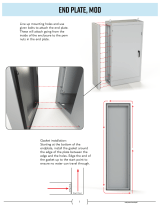
Internal Mounting
1. Place the supplied 1/2-inch gaskets on the two condenser side
cutouts as shown in the gasket drawing on page 8. The gaskets must
start and end at the middle top of the cutouts. The gaskets must remain
as one continuous piece around the cutouts. Bend gaskets around the
corners. Do not stretch the gaskets.
2. Remove the three #10 screws together with rubber washers from the
Rear Panel top.
3. Attach the supplied mounting angle to the Rear Panel top with the three
#10 screws and rubber washers (see Internal Mounting Drawing).
4. It is recommended that 1/4-inch x 11/4-inch mounting studs be used on
the customer enclosure door or panel. If not, use the hardware
supplied for air conditioner mounting.
If the air conditioner is mounted to the cabinet door you must be sure that the door hinges will support the
additional weight of the air conditioner. Also be certain that when the door is opened fully, the cabinet does not
become unbalanced. The actual weight of the unit can be found in the performance specifications.
EXTERNAL MOUNTING DRAWING
INSTALL THE MOUNTING PLATE W/STUDS
TO THE OUTSIDE WALL OF THE CUSTOMER'S
ENCLOSURE BEFORE INSTALLING A/C UNIT.
NOTE:
ENCLOSURE WALL
TYP. (3) PLACES
1/4'' NUT
CUSTOMER'S
ENCLOSURE
TYP. (3) PLACES
BOLT 1/4'' X 1-1/4''
RUBBER WASHER
MOUNTING PLATE
WITH STUDS
TOP SECTION
OF A/C UNIT
BOTTOM SECTION
OF A/C UNIT
RUBBER WASHER
1/4'' NUT
1/4'' NUT
TIGHTEN NUT TO
CLOSE GAP
INTERNAL MOUNTING DRAWING
MOUNTING BRACKET
1/4'' NUT (3)
ENCLOSURE
WALL EXTERIOR
TOP SECTION
OF A/C UNIT
BOTTOM SECTION
OF A/C UNIT
RUBBER WASHER (3)
1/4'' BOLT OR STUD (3)
RUBBER WASHER (3)
1/4'' BOLT OR STUD (3)
1/4'' NUT (3)
6. Route the power cord through the discharge (upper) air cutout.
7. Move the air conditioner toward the enclosure panel so that the gap between the hook and the enclosure is about 1/2-inch.
8. Slowly move the lift truck down until the hook engages with the mounting plate. Continue to lower the lift truck. The air
conditioner will hang from the mounting plate flush against the mounting panel.
9. Insert screws through the holes in the mounting plate bottom flange and the enclosure panel. Install sealing washers
and nuts on each screw from inside the enclosure and tighten (see External Mounting Drawing).
MOUNTING PLATE DETAIL
MOUNTING
PLATE
WITH STUDS
MOUNTING PLATE IS NOT SYMMETRICAL.
INSTALL WITH LONGER SECTION AT THE
TOP AND SHORTER SECTION AT THE BOTTOM.
NOTE:
SHORTER
SECTION
AT BOTTOM
LONGER
SECTION
AT TOP

8
Drawings and Dimensions
15.07
[382.8]
14.69
[373.1]
7.39
[187.7]
1.38
[35.1]
22.48
[580.0]
6.10
[154.9]
(6) .312
[7.9] DIA.
HOLES
.30
[7.6]
47.32
[1201.9]
1.0
[25.4]
1.20
[30.5]
7.26
[184.4]
7.26
[184.4]
1.29
[32.8]
.24
[6.1]
46.07
[1170.2]
1.04
[26.4]
11.14
[283.0]
TYP.
16.52
[419.6]
TYP.
1.30
[33.0]
11.05
[280.7]
28.77
[730.8]
16.25
[412.8]
1.54
[39.1]
TYP.
15.01
[381.3]
14.49
[368.0]
(6) .312 [7.9]
DIA. HOLES
13.60
[345.4]
TYP.
1.74
[44.2]
TYP.
5.00
[127.0]
(4) OPTIONAL
.312 [7.9] DIA.
HOLES
INTERNAL MOUNTING PLAN EXTERNAL MOUNTING PLAN
7.00
[177.8]
TYP.
7.00
[177.8]
7.00
[177.8]
1.54
[39.1]
2
1
START AND END GASKET MATERIAL
BELOW THE OPTIONAL MOUNTING
HOLES HERE. USE ONE CONTINUOUS
PIECE OF GASKET. BEND GASKET
AROUND THE CORNERS, DO NOT
STRETCH THE MATERIAL.
PLACE GASKET
ALONG EDGE OF
UNIT. (TYP.)
PLACE GASKET
BELOW OPTIONAL
MOUNTING HOLES.
PLACE GASKET
ABOVE OPTIONAL
MOUNTING HOLES.
PLACE GASKET
ALONG EDGE OF
UNIT. (TYP.)
EXTERNAL MOUNT GASKET PLACEMENT INTERNAL MOUNT GASKET PLACEMENT
GASKET 1/2" X 1/2" PART NUMBER 0639-61
START AND END GASKET MATERIAL
ABOVE THE UNIT CUTOUT HERE. USE
ONE CONTINUOUS PIECE OF GASKET.
BEND GASKET AROUND THE CORNERS,
DO NOT STRETCH THE MATERIAL.
START AND END GASKET MATERIAL
ABOVE THE UNIT CUTOUT HERE. USE
ONE CONTINUOUS PIECE OF GASKET.
BEND GASKET AROUND THE CORNERS,
DO NOT STRETCH THE MATERIAL.
START AND END GASKET MATERIAL
BELOW THE UNIT CUTOUT HERE.
USE ONE CONTINUOUS PIECE OF
GASKET. ROUTE GASKET ABOVE
OPTIONAL MOUNTING HOLES.
BEND GASKET AROUND THE
CORNERS, DO NOT STRETCH
THE MATERIAL.
MOUNTING PLANS
GASKET PLACEMENT
Dimensions, inches [mm], are for reference only and are subject to change.
WARM AIR RETURN FROM
ENCLOSURE
COOL AIR OUTLET
TO ENCLOSURE
1
2

9
9.07
[230.4]
46.93
[1192.0]
7.00
[177.8]
7.00
[177.8]
EXTERNAL DOOR MOUNT
SEE DETAIL "A"
POWER
CORD
6.10
[154.9]
22.48
[571.0]
.29
[7.4]
1.09
[27.7] 14.00
[356.0]
17.09
[434.1]
(4) 1/4-20
HOLES
13.60
[345.4]
1.75
[44.1]
11.14
[283.0]
TYP.
5.00
[127.0]
16.46
[418.1]
TYP.
11.08
[281.4]
14.44
[366.8]
1.34
[34.0]
.32
[8.1]
1.54
[39.1]
33.27
[845.1]
11.75
[298.5]
INTERNAL DOOR MOUNT
SEE DETAIL "B"
1.00
[25.4]
14.95
[379.7]
14.25
[362.0]
1.13
[28.7]
1.20
[30.5]
.30
[7.6]
7.00
[177.8]
7.00
[177.8]
1.54
[39.1]
1.38
[35.1]
7.39
[187.7]
FOR EXTERNAL DOOR MOUNT:
MOUNT PIVOT BAR ASSEMBLY
ONTO OUTSIDE OF ENCLOSURE
DOOR
FOR INTERNAL DOOR MOUNT:
INSTALL MOUNTING BRACKET
USING EXISTING HARDWARE
DETAIL "A" DETAIL "B"
PIVOT BAR
TO BE INSTALLED ON
CUSTOMER'S ENCLOSURE
DRAIN
ON/OFF POWER
SWITCH COVER
1
2
3
4
K_A_C9DP47L
Dimensions, inches [mm], are for reference only and are subject to change.
GA25600A - Rev. A
Drawings and Dimensions
FILTERED CONDENSER
AIR INLET (Ambient Air In)
CONDENSER OUTLET
(Warm Ambient Air Out)
WARM AIR RETURN FROM
ENCLOSURE
COOL AIR OUTLET
TO ENCLOSURE
1
2
3
4

10
Technical Data
KA3C9DP47L 9000 8000 125/-20 115/100 60/50 19.8 135
K2A3C9DP47L 9000 8000 125/-20 230/200 60/50 8.7 135
KA4C9DP47R 8000 7400 131/-20 115/100 60/50 19.2 135
K2A4C9DP47L 8000 7400 131/-20 230/200 60/50 8.7 135
Ambient Running Approximate
BTU/H BTU/H Temp. °F Amps Weight
Model Capacity 95°F/95°F Max./Min. Volts Hz 131°F/131°F (lbs.)
Major Component Replacements
KA3C9DP47L K2A3C9DP47L KA4C9DP47R K2A4C9DP47L
Part Part Number Part Number Part Number Part Number
Compressor 0665-76 0665-77 0665-131 0665-125
Compressor Run Capacitor 0452-54 0452-14 0552-52 0452-32
Condenser Impeller 0194-103 0194-50 0194-103 0194-50
Condenser Impeller Capacitor 0452-14 0452-05 0452-14 0452-05
Evaporator Impeller 0194-14 0194-15 0194-14 0194-15
Evaporator Impeller Capacitor 0452-06 0452-73 0452-06 0452-73
Condenser Coil 0666-48 0666-48 0666-48 0666-48
Evaporator Coil 0667-55 0667-55 0667-55 0667-55
Standard Features
Baked Powder Finish
Built-in Condensate Evaporator
CFC- Free Refrigerant
Closed-Loop Cooling
Condenser Impeller Speed Controller
Epoxy-Coated Condenser Coils
Heavy-duty Steel Shell
Low Temperature Control Thermostat
Mounts Internally or Externally
NEMA 12 & 3R Ratings Maintained (UL50)
Six-Foot [1.8m] (minimum) 3-Wire Power Cord
UL/CUL Listed
Accessories and Options
Compressor Short Cycle Protector
Enclosure Heater
Filter
Filter Recoating Adhesive
Internal Corrosion Protection
Other voltages and frequencies
Remote Thermostat Relay
Replacement Filters
Special materials or finishes
Special motors, line cords or connectors
Stainless Steel Shell
Temperature Alarm

11
VIII. Maintenance
Kooltronic Air-Cooled Air Conditioners require routine cleaning of the condenser coil (if necessary) and the air filter
to assure unimpeded airflow through the condenser heat exchanger. It is not possible to recommend specific
condenser coil or filter cleaning intervals, since the level and the nature of airborne particulate matter differs widely
with each installation. It is generally sufficient to clean the condenser coil and/or the aluminum mesh filter when the
outer surfaces appear covered with a thin layer of dust, lint or other foreign matter. The condenser coil can be
washed or blown out with air, depending on the foreign matter involved (see below - Filter and condenser coil
service). The aluminum mesh filter can be washed with warm water. Appropriate disposable replacement filters
are available from Kooltronic.
If routine condenser coil or filter service is neglected or delayed, the air conditioner will not perform at its design
capacity. The first indication of an excessively clogged condenser coil or air filter is usually a gradual increase of
temperature within the equipment cabinet. If operation is continued under these conditions, the compressor will be
shut off by the thermal overload device. The compressor will restart when its external temperature drops below the
protector threshold setting and the compressor will continue to cycle on and off. Continued operation under these
conditions will cause damage, shorten compressor life and void the warranty.
A. Filter and condenser coil service
The rear panel must be removed in order to clean the filters. After removal, the filters should be flushed
under warm running water with clean side up. If the accumulated dirt is oily, washing in a detergent bath
is recommended, followed by a warm water wash as above.
The exposed condenser coil must be cleaned by pressurized air or pressurized cleaning solution. Dirty
liquid will be removed through the condenser coil drain pan.
B. Blowers
The design life of the blowers used in all Kooltronic Air Conditioners is substantially in excess of 20,000
hours. All Kooltronic condenser and evaporator blowers are equipped with automatic-reset thermal
overload protectors.
CAUTION
If field replacement of a blower motor is necessary, most blower assemblies, including the mounting plate, are
readily removable. Each of the blower mounting plates is held to the air conditioner cabinet structure by screws
and nuts. For installation of the replacement blower, electrical connections may be broken at the terminal
block, or power leads may be cut and appropriately spliced together.
C. Compressor
All Kooltronic compressors are approved by UL and CSA, and require no maintenance. They are
hermetically sealed and charged at the factory, and equipped with automatic-reset thermal overload
protectors.
If the compressor fails, it is strongly recommended that the air conditioner be returned to Kooltronic for
service.
Before opening the air conditioner, disconnect all power.

12
.
IX. Trouble-Shooting
Each Kooltronic Air Conditioner is engineered for performance and built for reliability. They are designed to
require only routine maintenance. If your air conditioner should require warranty service, please
contact Kooltronic. If you require service out of warranty, we have compiled a trouble-shooting chart
to assist your service personnel. If additional assistance is required contact Kooltronic at (609) 466-3400.
Problem Cause Solution
Unit does not run. No Power. Check Power Source and electrical connection.
Check unit ON-OFF switch (UL Listed units only).
Check unit power cord connection to terminal block.
After initial 15 minute energization Return temperature is Normal Operation.
of air conditioner, compressor and between Thermostat set Check return air temperature.
condenser fan do not run. point and differential Check sensor connection on Thermostat.
(75°F to 86°F).
Unit not cooling. (Temperature Failed Thermostat Check Thermostat and Relay wire connections.
difference between return and or Relay. Replace Thermostat or Relay.
supply air is less than 10°F).
Evaporator Blower is running. Low Line Voltage. Check Nameplate Voltage against supply Voltage.
Compressor and Condenser Blower
do not run. Return temperature is Failed Compressor. Check Compressor wire connections.
above set point plus differential (90°F). Check Compressor overload.
Check Compressor Capacitor.
Replace Compressor.
D. Refrigerant Loss
Kooltronic Air Conditioners are subjected to a series of tests to detect refrigerant leaks, during and after
manufacture. It is possible that shipping or other damage, or microscopic leaks over a long period, may result
in the need for replenishment of refrigerant charge. When it has been verified by a Certified EPA Technician
that a refrigerant shortage does exist, the leak must be repaired. Then the unit may be evacuated and
recharged in the field by a Certified EPA Technician only.
CAUTION
E. Relocation
If your Kooltronic Air Conditioner has to be moved to another location by truck, the following precautions
should be taken:
■De-mount the air conditioner from the equipment, controller or enclosure.
■Conform to the applicable provisions of PROCEDURE FOR PROPER PACKING AND SHIPMENT OF
KOOLTRONIC AIR CONDITIONERS in this manual under
Section III. "PRODUCT HANDLING".
Refer to the data on the unit nameplate which specifies the type of
refrigerant and the amount of charge in ounces.

13
Problem Cause Solution
Unit not cooling. (Temperature Failed Evaporator Blower. Check Blower wire connections.
difference between return and Check blower capacitor.
supply air is less than 10°F). Replace Evaporator Blower.
Compressor and Condenser Blower
are running. Evaporator Blower does
not run.
Unit not cooling. (Temperature Low Refrigerant charge. Check discharge and suction pressure for
difference between return and Refrigerant leak.
supply air is less than 10°F). Failed Condenser Blower. Check Blower wire connections.
Compressor and Evaporator Blower Check Blower Capacitor.
are running. Condenser Blower does Replace Condenser Blower.
not run. Failed Speed Controller. Check Speed Controller Sensor.
Replace Speed Controller.
Unit not cooling. (Temperature Condenser or Evaporator Clean Coil.
difference between return and Coil clogged.
supply air is less than 10°F).
Evaporator Blower, Condenser Loss of Refrigerant. Locate and repair leak.
Blower and Compressor are running.
Ice on Evaporator Coil. Clean Evaporator Coil.
Check discharge and suction pressure for
Refrigerant leak.
Check for any obstruction of Evaporator airflow.
Check and seal all openings.
Excessive condensate Eliminate the frequency of door openings.
draining and loss of A/C
sensible cooling performance.
Unit overcooling. Failed Thermostat. Check Thermostat wire connections.
Evaporator Blower, Condenser Replace Thermostat.
Blower and Compressor are running. Failed Relay. Replace Relay.
Compressor cycling more than Short circuiting of air Provide baffle in the enclosure separating A/C
10 cycles per hour. between A/C discharge Outlet and inlet.
and inlet openings.
Excess vibration. Defective motor in Blower. Replace motor.
Defective wheel in Blower. Replace wheel.
Bad Compressor. Replace Compressor.

X. Standard Warranty
THIS WARRANTY CONSTITUTES THE ENTIRE WARRANTY WITH RESPECT TO THE PRODUCT AND IS IN
LIEU OF ALL OTHERS, EXPRESSED OR IMPLIED, INCLUDING ANY WARRANTY OF MERCHANTABILITY
AND WARRANTY OF FITNESS FOR A PARTICULAR PURPOSE AND IN NO EVENT IS KOOLTRONIC
RESPONSIBLE FOR ANY CONSEQUENTIAL DAMAGES OF ANY NATURE WHATSOEVER.
RETURN AUTHORIZATION (RA) PROCEDURE
KOOLTRONIC products are warranted to be free of defects
in workmanship, materials and components. The following
warranty periods apply from date of shipment:
■Air moving devices/components and hermetic system
components: 1 year
■Spare parts, except filters: 90 days
The above warranty applies when the equipment is operated
under the following conditions:
■Ambient temperature not in excess of 125°F (52°C) in
normal atmosphere or as stated on product nameplate
■Voltage variation no greater than ± 10% from nameplate
rating
■Frequency variation no greater than ±3Hz from nameplate
rating
■Maximum cooling load no higher than air conditioner
nameplate rating
■Waiting five minutes before restarting air conditioner after
intentional or accidental shutoff
■Compliance to all other installation, maintenance and
operating instructions, as supplied
■The purchaser assumes the responsibility of grounding
the unit and installing it in accordance with local electrical
and safety codes, as well as the National Electric Code
(NEC) and OSHA
KOOLTRONIC cannot assume responsibility for
mis-application of its products or the erroneous
selection of an inappropriate product by a non-
authorized KOOLTRONIC representative. Our
applications engineers will gladly assist in the
selection of the proper product, provided all
required details of the application are furnished.
■All returns require a Return Authorization number whether
the return is for warranty or non-warranty repair, rotation of
stock, damage or any other reason. Returns without an RA
number will be refused.
■Customer must call KOOLTRONIC After Sale Kare (ASK),
Pennington, New Jersey (609 • 466 • 3400) to obtain an RA
number, or email [email protected].
■The following information is required when an RA is
requested:
- Original customer Purchase Order number and date
- Date product was received by customer
- Number of parts to be returned
- Product description, model and serial number
- Reason for return
- Action requested
- Contact name, telephone, FAX numbers and e-mail address
■Pack unit in a suitable container for shipment, preferably the
original packaging if available. All Air Conditioners must be
returned in an upright position properly secured to a pallet.
Improper packaging may void warranty claim. If an Air
Conditioner is received laying down or shipped via UPS or
similar small parcel service the warranty will be void.
■Mark carton prominently with KOOLTRONIC’s Return
Authorization Number.
■Enclose all pertinent documents.
■Freight charges on all products returned to KOOLTRONIC
shall be paid by the customer. Unauthorized collect shipments
will be refused.
■If a unit is repaired under Warranty, KOOLTRONIC will pay
the freight charges both ways within the Continental USA
at KOOLTRONIC’s negotiated rates. Warranty repaired
units will be returned to customer at KOOLTRONIC expense
only within the Continental USA.
■All authorized returns are subject to a restocking fee.
KOOLTRONIC assumes no liability beyond the repair or
replacement of its own product. This Warranty does not
cover:
■Labor or reimbursement of labor for evaluation, removal,
installation, repair, or cost of any warranted part, unless
authorized in writing by KOOLTRONIC
■Use of equipment for other than its designed purpose or
operating conditions
■Operation in harsh, oily, corrosive or other abnormal
environmental conditions, without the proper filtration,
sealing, protective coatings and/or weather protection
■Damage to hermetic system resulting from continuous
operation with dirty or clogged air filters or improper or
negligent maintenance
■Use of refrigerant other than designated
■Customer modification or abuse
■Shipping damage or other accident (Claims for shipping
damage are the responsibility of the customer. Timely
claims must be filed by the customer with the freight carrier)
■Cracked or broken hermetic tubing, brazed joints or other
internal damage caused by shipping or mishandling
■Damage caused by shipping units attached to an
enclosure
■Any and all conditions resulting from noncompliance with
the preceding operating conditions
■Returned freight must be paid by customer
■This standard warranty does not apply to custom
products. Consult your KOOLTRONIC representative
for limitations
14
/