Page is loading ...

1
Copyright © 2021 Reserves the right to make changes to this product without further notice.
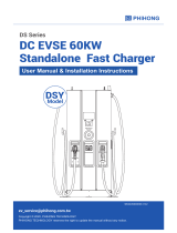
30kW Moveable
DC Fast Charger
User Manual & Installation Instructions
DM Series
CE
Model

2

3
CONTENT
Introductions ������������������������������������������������������������������������������ 1
Features ������������������������������������������������������������������������������������� 1
Applications �������������������������������������������������������������������������������� 1
1� Basic User Interface ���������������������������������������������������������������� 2
2. Specication ��������������������������������������������������������������������������� 4
2.1 Product Specication ������������������������������������������������������� 4
2�2 DM30 Version Description ������������������������������������������������ 6
2�2 LED Indication and Operation Status ��������������������������������� 6
2�3 Dimmensions (Unit: mm) �������������������������������������������������� 7
2�4 Direction of cooling Airflow ���������������������������������������������� 7
3� Installation Instruction ����������������������������������������������������������� 8
3�1 Before Installation ������������������������������������������������������������ 8
3�2 Grounding and Safety Requirement ����������������������������������� 9
3�3 Unpack the charger �������������������������������������������������������� 11
3�4 Recommended Tools for Installation and Inspection �������� 14
3�5 Installation Procedure ���������������������������������������������������� 15
3�6 Installation Inspection & Commissioning ������������������������ 17
4� Network Setting ������������������������������������������������������������������� 20
4�1 Wi-Fi Network Setting ���������������������������������������������������� 20
4�2 3G/4G Setting����������������������������������������������������������������� 22
4�2�1 SIM Card Installation ��������������������������������������������������� 22
4�3 Time setting ������������������������������������������������������������������ 24
5� Operation Process ����������������������������������������������������������������� 26
5�1 Operating Sequence ������������������������������������������������������� 26
5�2 Operating Procedure ������������������������������������������������������� 26
5�3 Troubleshooting ������������������������������������������������������������ 32
5�4 Status Codes ������������������������������������������������������������������ 33
6� Maintenance ������������������������������������������������������������������������ 53
6�1 General Maintenance ������������������������������������������������������ 53
6�2 Replacement Kits and Accessories ��������������������������������� 54
7� Limited Product Warranty ������������������������������������������������������ 55
Appendix - Package list ������������������������������������������������������������� 56

1
Introductions
The Moveable DC Fast Charger is the top choice to power battery electric vehicles
(BEV) and plug-in electric vehicles (PEV). It is designed for quick charging in both
public and private locations, such as retail and commercial parking spaces, fleet
charging stations, highway service areas, workplace, residence, etc.
The Moveable DC Fast Charger has the advantage of mobility, it is freely to access
EV and charging. The Moveable DC charger also has network communication
capability. It is able to connect with remote network systems and provide drivers
of electric cars real-time information, such as the location of charging stations,
charging progress and billing information. The Moveable DC Fast Charger has a
clear user interface with function buttons, safety certifications and an excellent wa-
terproof and dust proof design to provide the best choice for outdoor environments.
Features
• Moveable design and pluggable power modules make installation easy and
flexible.
• Offers customers the convenience of start/stop charging control from an
authorized RFID smart card or mobile APP.
• Built on latest industry standards for DC charging.
• Carries an outdoor rating capable of withstanding solid and liquid intrusions in
outdoor settings making the unit more stable and highly reliable.
• Provides a high-contrast, screen interface with multi-function buttons.
Applications
• Parking garage
• Commercial fleet operators
• EV dealer workshops
• Auto service center
1

2
1. Basic User Interface
Main unit :
Antenna
Emergency Stop
USB Port
RJ45 Port
Cable holder
Front Caster with push-down brake
Door handle
CEE Socket 5pin 3P+N+PE Male
380~415Vac 63A
Charger Gun Cable Holster
Rear Caster
Handle
Indication Light
7" Information Screen
Right Button
Left Button
RFID Card Reader
• Charging Status
• Alarm information
• User Authorization
Indication Light
2

3
Charger Gun Holster Charger Gun Storage
Notice: According to EN-17186 require-
ment, this document lays down harmo-
nized identifiers for power supply for elec-
tric road vehicles. The requirements in this
standard are to complement the informa-
tional needs of users regarding the com-
patibility between the EV charging stations,
the cable assemblies and the vehicles that
are placed on the market. The identifier is
intended to be visualized at EV charging
stations, on vehicles, on cable assemblies,
in EV dealerships and in consumer manu-
als as described.
3

4
2. Specication
2.1 Product Specication
Model Name DMYx301 Series
AC
INPUT
Voltage Rating 3Φ380 ~ 415Vac (±15%)
Input Current Rating 47A
Max. Input Power 33 kVA
Electrical Distribution 3P+ N +PE (Wye Configuration)
Power Grid System TN / TT
Frequency 50/60Hz
Power factor > 0.99
Efficiency > 94%, at optimize V/I point
DC
OUTPUT
One output CCS2 or CHAdeMO or GB/T
Output voltage range
DC 150 ~ 950V (CCS2)
DC 150 ~ 500V (CHAdeMO)
DC 150 ~ 750V (GB)
Max. output current
CCS2:80A@150Vdc ~ 375 Vdc
when output voltage up to 950Vdc
the output current is 31.5A
CHAdeMO: 60A@150Vdc ~ 500Vdc
GB/T: 80A@150Vdc ~ 375Vdc
when output voltage up to750Vdc
the output current is 40A
Max. output power DC 30kW
Aux. Power(Only for GB/T) 12Vdc, 10A
Voltage accuracy +/- 2%
Current accuracy +/- 2%
Electrical Isolation Isolation between input and output
Standby Power < 100W
Communication External Ethernet, Wi-Fi and 3G or 4G
Internal CAN Bus / RS485
Input Protection OVP, OCP, OPP,OTP, UVP, RCD, SPD
Output Protection SCP, OCP, OVP, LVP OTP, IMD
4

5
Internal Protection OTP, AC contactor detection, DC contactor detection,
Fuse detection
Load Management Via OCPP 1.6JSON
User Interface &
Control
Display 7-inch LCD
User Authentication
RFID: Support ISO 14443A/B, ISO
15693, FeliCa Lite-S (RCS966),
OCPP, 2D barcode, APP, Mobile
Payment
Backend support OCPP 1.6 JSON
Environmental
Conditions
Operation Temperature
-30°C to 50°C (-22°F to 122°F), will
derating from 50°C (122°F) and
above
Storage Temperature -40°C to 70°C (-40°F to 158°F)
Relative Humidity 5%~95% RH, non-condensing
Altitude ≦2000 M (6560 ft)
Regulations
Safety (Not Including GB) IEC 61851-1, IEC 61851-23
EMI/EMC IEC 61851-21-2
Charging Interface
CHAdeMO Ver 1.2
CCS DIN 70121
GB/T 27930
Mechanical
Specifications
Dimensions (WxDxH mm) 589x620x1020
Weight (typ.) ≦80kg
DC Charging Connector CCS2 or CHAdeMO or GB/T
Charging Cable Length <5M, Optional other length
Charging Cable Number One
Input cable and connection 10M cable with CEE socket
Cooling Fan cooling
Ingression Protection IP55
Anti-vandalism IK10 (does not include LCD & RFID
cover)
Acoustic Noise (dB(A) 65dB(A) (Pout with DC 25kW at
Rt=30°C
5

6
2.2 DM30 Version Description
The DM30 series are available in different versions depending on the charging
connectors, below table shows the available combinations.
Version Connector Type
DMYx301E00 CCS2
DMYx301J00 CHAdeMO
DMYx301G00 GB
DMYx301U00 CCS1
DMYx301M00 CCS2
2.2 LED Indication and Operation Status
Status LED Light Remark
Standby Green
Fault Red
Charging Blue
6

7
2.3 Dimmensions (Unit: mm)
Main Size of Charger:
589 155
740
92 Ref 160
490 130
2.4 Direction of cooling Airflow
Air Out Air In
7

8
• Read all the instructions before using and installing this product.
• Do not use this product if power cable or charging cable have any damage.
• Do not use this product if the enclosure or charging connector are broken or
open or if there is damage.
• Do not put any tool, material, finger or other body part into the charging connec-
tor or EV connector.
• Power feed must be 3 Phase Wye configuration with TN(-S)/TT grounding sys-
tems.
• In the installation of TN(-S) system: the neutral (N) and the PE of the power
distribution are directly connected to the earth. The PE of the charger equipment
is directly connected to the PE of power distribution and separate conductor for
PE and neutral (N).
• In the installation of TT system: the neutral (N) and the PE of the power distri-
bution are directly connected to the earth. The PE of the charger equipment is
isolated to the PE of power distribution to the earth.
• The capacity of power supply should be higher than 33.0kVA in order to function
correctly.
• The product should be installed in free air area and keep at least 30cm clearance
distance to all air vent of the product.
• Need sufficient space for product installation and maintenance, please keep not
less than 60cm clearance distance from all around the product.
• Do not move the charge in speed higher then 1Meter/second (about 3.6Km/h
normal walking speed) , and do not move at bumpy surface .
3. Installation Instruction
3.1 Before Installation
WARNING: The product should be installed only by a licensed contrac-
tor and/or licensed technician in accordance with all building codes,
electrical codes and safety standards.
WARNING: The product should be inspected by a qualified installer
prior to initial use. Under no circumstances will compliance with the
information in this manual relieve user of his /her responsibilities to
comply with all applicable codes and safety standards.
8

9
• The product must be connected to a grounded, permanent wiring system. Con-
nections shall comply with all applicable electrical codes.
• Ensure no power is connected at all times when installing, servicing, or maintain-
ing the charger.
• Use appropriate protection when connecting to main power distribution network.
• Use appropriate tools for each task.
• Do not apply electrical power to charger or charging cars before the charger is
well parked.
3.2 Grounding and Safety Requirement
CAUTION: The disconnect switch for each ungrounded conductor of
AC input shall be provided by installation contractor or technician.
CAUTION: A cord extension set or second cable assembly shall not be
used in addition to the cable assembly for connection of the EV to the
EVSE.
NOTICE
It is recommended to conduct WI-Fi and 4G signal strength while
charger installation. The RSSI (Received Signal Strength Indication)
value is considered as good as higher than -65dBm. Poor connec-
tion quality might interrupt charging process or data transaction.
9

10
3�2�1 Service Wiring
• Ground Connection
Always connect the Neutral at the service to Earth Ground. If ground is not pro-
vided by the electrical service then a grounding stake must be installed nearby.
The grounding stake must be connected to the ground bar in the main breaker
panel and Neutral connected to Ground at that point.
• 400Vac(Line to Line) Three-Phase
CAUTION!
This is feed from Wye-connection power grid, the Wall Mount DC Fast
Charger can connect to L1, L2 or L3, and Neutral. Earth ground must be
connected to neutral at only one point, usually at the breaker panel.
400V Three-Phase Wiring Connection
WARNING!
Earth Connection is Essential!
PE
230Vac
230Vac
230Vac
400Vac
Neutral
L3
L1
L2
DANGERS
Be Aware of High Voltage!
10

11
3.3 Unpack the charger
• The product is Direct current (DC) charger, the packing design passed the pack-
aging simulation test, if the packaging is damaged cause by overturning, falling
or external impact during transportation, it may cause the product damage or de-
fects. if there is any serious damage to the packaging when receiving the goods,
please notify manufacturer (supplier) about your findings.
• Receiving the DC 30KW Moveable. The product is delivered by a transport com-
pany to a warehouse or specified location where it will be handed over. Trans-
porting the DC 30KW Moveable to its final location (last mile service) is not stan-
dard included in the order.
• NOTICE: The delivery truck unloads the pallet carrying the DC 30KW Moveable.
The movement of the 30KW Moveable to its final location is the responsibility of
the customer / contractor.
• Checking the TiltWatch sensors: If the TiltWatch indicator is tilted over 80°
• 1.Do not refuse the delivery / receipt.
• 2.Make a notation on the delivery receipt and inspect cabinet for damage.
• 3.If damage is discovered, leave cabinet in original package and request immedi-
ate inspection from carrier within 3 days of delivery.
• 4.Contact supplier to notify us about your findings.
11

12
Remove the surrounding boards
STEP 1�
STEP 2�
Remove the packaging films and the paper covers.
WARNING!
Charger weight might >80Kg!
Be careful during unpack process.
12

13
Remove the surrounding cardboards and films.
STEP 3�
13

14
3.4 Recommended Tools for Installation and
Inspection
3�4�1 Recommended Tools for Installation
Type Description
Philips Screwdriver No. 2 and 3
Shifting Wrench 8" (24mm)
Ball-Head Hex Key 2.5mm and 5mm
Socket Screwdriver No. 8 and 10
Electrical Tape Black / 15mm Width
AC Input Cable AWG 5 (16mm2) Cable x 5
(L1,L2,L3,N,PE)
Ring Terminal
AWG 5 x 5 (L1,L2,L3,N,PE)
Ring Terminal (inside diameter is
6.4mm; outer diameter is 15.1mm)
Crimping Pliers for Ring Terminal
Wire Stripper
Wire Cutters
3�4�2 Recommended Tools for Inspection & Commissioning
Type Description
EV or EV Simulator Meet CHAdeMO/CCS1 standard
Multiple Meter 1000V
Current Probe 100Amp
RFID Authorized Card
RFID No Valid Card
Door Key
Needle-Nose Plier
Wi-Fi /4G signal quality checker Recommended
14

15
3.5 Installation Procedure
STEP 1�
STEP 2�
Place the Moveable charger on the flat ground, Push down all front wheel-brakes
until hearing the click sound.Suggest to place the moveable charger in a place
where the vehicle will not pass. And confirm to return the charger after use to
avoid being hit by the car to damage.
Open the side door and fasten the female CEE plug on the extension cable into
the male CEE socket on charger, make sure both sides are inter-locked appro-
priately then close the door.
15

16
STEP 3�
* Not following installation instruction will cause charger damage.
* NOTICE A 50A NFB with 30mA RCD-Type A is recommended.
STEP 4�
Turn on the power source and then operation screen will be ready within 30
seconds.
Fasten AC power cord to the wall socket or distribution box according to local
regulation and shall be operated by qualified technician.
16

17
3.6 Installation Inspection & Commissioning
3�6�1 Environmental Check
Item Status Remark
Ambient Temperature
Ambient Humidity
Sunshade Recommended but not
required.
Rain Canopy Recommended but not
required.
Air Circulation / Drafty
Dust Level
Anti-Vandalism Measures
3�6�2 External Infrastructure Readiness & Check
Item Status Remark
Input Wirings & Terminals
Key & Lock of Cabinet Door
No Fuse Breaker(NFB)
Notice:
Current rating of NFB shall
be higher than 50Amp
Residual Current Device (RCD)
Notice:
Maximum RCD residual cur-
rent shall not excess 30mA
Input Electricity Capacity
Input Electricity Configuration
Grounding Resistance (<10Ω)
Grounding System (TN)
Input Voltage & Frequency
Network Connection & Quality Wi-Fi , 4G > -65dBm
17
/