Page is loading ...

Manual # P80170008B - Date:2007/12/04
Grill Island
Model CGI08ALP
OPERATOR'S MANUAL
Ÿ
Ÿ
NOTE TO ASSEMBLER / INSTALLER:
Leave this manual with the consumer.
NOTE TO CONSUMER:
Keep this manual for future reference.
RECORD YOUR SERIAL # __________________
(see silver CSA label on main body of grill)
IMPORTANT:
Ÿ
NOTE: Complete Island Kit requires 3 boxes
Failure to comply with these instructions could
result in a fire or explosion that could cause
serious bodily injury, death or property damage.
Whether this grill was assembled by you or
someone else, you must read this entire manual
before using your grill to ensure the grill is
properly assembled, installed and maintained.
Use your grill at least 3 feet away from any
wall or surface. Use your grill at least 3 feet
away from combustible objects that can melt or
catch fire such as vinyl or wood siding, fences
and overhangs or sources of ignition including
pilot lights on water heaters and live electrical
appliances.
THIS GAS APPLIANCE IS DESIGNED FOR OUT-
DOOR USE ONLY.
Never use your gas grill in a garage, porch,
shed, breezeway or any other enclosed area.
Never obstruct the flow of ventilation air
around your gas grill housing.
Never disconnect the gas regulator or any gas
fitting while your grill is lit. A lit grill can ignite
leaking gas and cause a fire or explosion which
could result in property damage, personal injury
or death.
Ÿ
Ÿ
Ÿ
Ÿ
Ÿ
Ÿ
WARNING
! !
Ÿ
FREE HELP
FROM THE GRILL EXPERTS
Do not return to the store. At Grand Hall we're
the experts on this product and trained to help
you with:
Assembly questions
Grill operation
Replacement of damaged or missing parts
Ÿ
Ÿ
Ÿ
visit www.grandhall.com or call:
1-800-761-5456
Monday - Friday 8:00am-4:30pm CST

2
Table of Contents
Primary Safety Warnings...........................1-3
Pre-Assembly Instructions..............................3
Part Diagrams and Lists........................4-13
Assembly Instructions.............................14-20
Use & Care Instructions:
• Gas Safety and Leak Tests...........21-23
• Lighting Instructions............................24-25
• Troubleshooting.........................................25
• Rotisserie Instruction...........................26-28
• Faucet Operation....................................29
• Refrigerator Instruction.............................30
• Cleaning and Maintenance................31-32
• Cooking Guide...................................A1-A6
• Frequently Asked Questions............A7-A8
Warranty Terms...........................Back Cover
WARNING
! !
•
Keep gas regulator hose away from hot grill
surfaces and dripping grease. Avoid unneces-
sary twisting of hose. Visually inspect hose
prior to each use for cuts, cracks, excessive
wear or other damage. If the hose appears
damaged do not use the gas grill. Call Grand
Hall at 1-800-761-5456 for a certified replace-
ment hose.
California Proposition 65
Combustion byproducts produced when using
this product contain chemicals known to the
State of California to cause cancer, birth de-
fects, or other reproductive harm.
Brass components on the grill, such as hose
fittings, propane cylinder valves (sold sepa-
rately) and burner valve stems, contain lead
which is known to the State of California to
cause cancer, birth defects, or other reproduc-
tive harm.
Never use charcoal or lighter fluid in this gas
grill. Failure to comply with these instructions
could result in a grease fire or explosion that
could cause serious bodily injury, death or
property damage.
The Grease Draining Tray and Grease Recep-
tacle must be visually inspected before each
grill use. Remove any grease and wash Grease
Draining Tray and Grease Receptacle with a
mild soap and warm water solution. Failure to
comply with these instructions could re-
sult in a grease fire or explosion that could
cause serious bodily injury, death or prop-
erty damage.
LPG models must be used with Liquid
Propane Gas and the regulator assembly
supplied. Natural Gas models must be used
with Natural Gas only. Any attempt to convert
the grill from one fuel type to another is
hazardous and must be performed by a
qualified gas technician only, using a NG
Conversion Kit purchased from Grand Hall.
•
•
•
•
Do not store or use gasoline or other
flammable liquids or vapors in the
vicinity of this or any other appli-
ances.
An LP cylinder not connected for use
shall not be stored in the vicinity of
this or any other appliance.
DANGER
!
!
1.
2
3.
4.
If you smell gas:
Shut off gas to the appliance.
Extinguish any open flame.
Open lid.
If odor continues, keep away from
the appliance and immediately call
your gas supplier or your fire
department.
1.
2.
WARNING
! !

3
Pre-Assembly Instructions For Your Safety
To expedite the assembly process follow these
general guidelines:
Grill Information Center 1-800-761-5456
8am-4:30pm CST, Monday through Friday
Spiders and small insects can spin webs and
nest in the grill Burner Tubes during transit and
warehousing which can lead to a gas flow
obstruction resulting in a fire in and around the
Burner Tubes. This type of "FLASHBACK FIRE"
can cause serious grill damage and create an
unsafe operating condition for the user.
To reduce the chance of FLASHBACK
FIRE you must clean the Burner Tubes
as follows before initial use. Also do this
at least once a month in summer and fall or
whenever spiders are active in your area, and if
your grill has not been used for an extended
period of time.
WARNING
! !
Failure to comply with these instructions may
result in a hazardous situation which, if not
avoided, may result in injury.
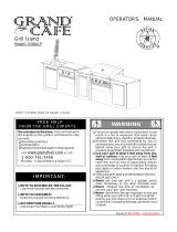
For safe operation ensure the Gas Valve Assem-
bly Orifice is inside the Burner Tube before using
your grill. See figure. If the Orifice is not inside
the Burner Tube, lighting the Burner may cause
explosion and/or fire resulting in serious bodily
injury and/or property damage.
METHOD 1: Bend a stiff wire or wire coat
hanger into a small hook as shown and run
the hook through the Burner Tube and inside
the Burner several times to remove debris.
METHOD 2: Use a bottle brush with a flexible
handle and run the brush through the Burner
Tube and inside the Burner several times to
remove any debris.
METHOD 3: Use an air hose to force air
through each Burner Tube. The forced air
should pass debris or obstructions through
the Burner and out the Ports.
TO CLEAN BURNER TUBE, INSERT HOOK
HERE
Burner Tube
9
Grill Installation Codes
The installation must conform with local codes or, in the
absence of local codes, with the National Fuel Gas
Code, ANSI Z223.1/NFPA 54, Storage and Handling of
Liquefied Petroleum Gases, ANSI/NFPA58,Natural Gas
and Propane Installation Code, CSA B149.1, Propane
Storage and Handling Code, B149.2.
Orifice
Burner Tube
Gas Valve Assembly
Carefully lift each Burner up and away from the
Gas Valve Orifice.
Check and clean Burner/Venturi Tubes for
insects and insect nests. A clogged tube can
lead to a fire beneath the grill.
Refer to the figure below and perform one of
these 3 cleaning methods:
Remove the screws from the rear of each Main
Burner using a Phillips Head Screwdriver.
1.
2.
3.
4.
Burner Port
Foot
WARNING
! !
This appliance, when installed, must be electri-
cally grounded in accordance with local codes
or, in the absence of local codes, with the
National Electrical Code, ANSI/NFPA 70, or the
Canadian Electrical Code, CSA C22.1.
Keep any electrical supply cord and the fuel
supply hose away from any heated surfaces.
•
•
CAUTION
!
When using electrical appliances, basic
safety precautions should always be used.
!
1.
WARNING
! !
Do not store spare LP cylinder
within 10 feet (3m) of this appliance.
Do not store or use gasoline or
other flammable liquids and
vapors within 25 feet (8m) of this
appliance.
When cooking with oil/grease, do
not allow the oil/grease to get
hotter 350°F (177°C)
Do not leave oil/grease unattended.
4.
2.
3.
Tools Required for Assembly:
Protective work gloves
Phillips Head Screwdriver
While it is possible for one person to unpack this gas
grill, obtain assistance from another person when
handling the large pieces.
Use the Hardware and Part Diagrams to ensure all
items are included and free of damage.
Do not assemble or operate the grill if it appears
damaged. If there are damaged or missing parts
when you unpack the shipping box or you have
questions during the assembly process, call the:
•
•

4
Hardware Pack Parts List for Model CGI08ALP
* Two Batteries/AA included in the Hardware Pack.
PART # PART DESCRIPTION QTYPURPOSE OF PART
P06024006A Hardware Pack 1 For use in assembly (Grill and Range)
S112G04061 Phillips Head Screw 1/4"x3/8" 8 Install Cart Frames to Left / Right Bowl Panels
S162M04201 Hex Head Screw M4X20mm 2 Secure Faucet Washer and Faucet Bracket to Faucet
S233G04084 Wing Bolt 1/4"x1/2" 1 Secures Gas Tank to Tank Holder
P05515017L Wrench
1
Adjust level on Island Assembly Set
Already packed in the Faucet Assembly Kit Box
Already Installed on Tank Holder
Already packed in the Cooking Components Box
Phillips Head Screw 1/4"x3/8"
Qty. 8
Part # S112G04061
Wing Bolt 1/4"x1/2"
Qty. 1
Part # S233G04084
Hardware already installed on the Tank Holder
Wrench
Qty.1
Part # P05515017L
Already packed in the Cooking Components Box
• Always purchase the correct size and grade of battery most suitable for the intended use.
• Replace all batteries of a set at the same time.
• Clean the battery contacts and also those of the device prior to battery installation.
• Ensure the batteries are installed correctly with regard to polarity (+ and -).
• Remove batteries from equipment which is not to be used for an extended period of time.
• Remove used batteries promptly.
CORRECT BATTERY USE

5
Parts Diagram for Model CGI08ALP Grill
82
14
13
21
22
1
2
3
5
6
7
10
8
9
16
17
23
27
28
29
34
35
37
44
31
24
19
18
15
12
25
45
4
11
32
33
42
36
43
26
30
74
39
40
38
5
41
41
46
47
48
49
50
51
52
53
54
55
56
57
60
59
57
61
62
58
71
72
73
75
76
77
78
67
68
70
20
64
65
66
63
69
79
77
78
81
80

6
Parts Diagram for Model CGI08ALP Range
1
3
4
24
5
6
7
25
8
9
10
14
13
12
15
16
17
18
19
20
21
23
28
29
31
32
34
26
35
37
38
39
40
41
56
45
46
47
48
22
54
60
57
59
61
58
55
42
2
11
30
43
50
57
53
49
62
27
63
51
52
36
64
65
30
31
67
66
66
67
68
69
44
13
70
71
72
73
33

7
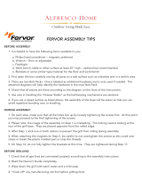
Parts Diagram for Model CGI08ALP Island
1
9
10
14
17
18
22
11
20
21
15
13
12
19
16
2
3
7
3
6
7
4
5
23
24
8

8
Parts List for Model CGI08ALP Grill
KEY DESCRIPTION PART# QTY
1 Lid Assembly
P00147063A
1
2
Temperature Gauge
P00601071A
1
3
Lid Handle
P00205086B
1
4 Heat Insulating Spacer
P06801022A
2
5 Protective Pad P05518011 I 2
6 Cooking Rack/Secondary P01516004B 1
7 Cooking Grid, 13" P01604013B 2
8 Cooking Grid, 6.4" P01604031B 1
9 Burner/Main P02008032A 3
10 Infrared Burner Assembly P02005010A 1
11 Thermocouple P05305019A 1
12
Savor Plate
®
P01708033E 3
13
Savor Plate
®
Bracket, Front
P033280504 3
14
Savor Plate
®
Bracket, Rear
P033280514 3
15 Burner Bracket P02210034A 1
16 Back Burner Assembly P02007068A 1
17 Back Burner Electrode P02614025A 1
18 Back Burner Wind Shield P06906046B 1
19 Back Burner Orifice P06534005A 1
20
Refrigerator Bracket, Left P03329012D 1
21 Back Burner Thermocouple P05305022A 1
22 Back Burner Thermocouple Bracket P03328047C 1
23 Bowl Panel, Front P0073878KA 1
24 Burner Heat Shield P06906045A 1
25 Grease Tray Heat Shield P06904020C 1
26 Grease Tray Heat Shield, Lower P06903050M
1
27 Electric Wire Set P02615121A 1
28 Gas Collector Box with Electrode P02609010B 3
29 Gas Valve/Manifold Assembly Y0060571 1
30 Grease Draining Plate P06902006B
2
31 Lighting Stick P05507008A 1
32 Bowl Support Bracket, Left P01301006D 1
33 Bowl Support Bracket, Right P01302006D 1
34 Control Panel Extension P02909768S 1
35 Control Panel Upper
P02915061S
1
36 Control Panel P02915051S 1
37 Electric Ignitor, 6-port P02502265C 1
38 Control Knob Seat P03415014A 5
39 Control Knob P03429065V 3
40 Control Knob For Back Burner/Infrared Burner P03429075V 2
41 Control Knob Spring P05504021A 5
42 Name Plate P00407010D 1
43 Electric Ignitor Protector P05545002A 1
44 Grease Tray P02717454A 1
45 Grease Tray Handle P00213012B 1
46 Cart Panel, Top P07805002A 1

9
Parts List for Model CGI08ALP Grill
KEY DESCRIPTION PART # QTY
47 Cart Panel, Front
P07621009D 1
48 Cart Frame for Front Panel
P03344010D 1
49
Cart Frame, Front P00907012C 1
50 Cart Panel, Rear/Left
P07621010D 1
51 Cart Panel, Rear/Right
P07621011D 1
52 Cart Frame for Rear Panel
P03344012D 1
53
Cart Frame, Rear
P00907013C
1
54 Cart Panel, Right
P07620003D 1
55
Cart Frame, Right P03305056D 1
56 Bowl Support Panel, A
P03305057D 1
57 Cart Panel, Middle/Right
P03305058D 2
58
Refrigerator Bracket, Right P03329013D 1
59 Slide Set
P05516132C
1
60 Bowl Support Panel, B
P03305059D 1
61
Drawer P01901011B 1
62
Handle/Drawer P00215033B 1
63 Door for Refrigerator
P04301040A 1
64 Hose Holder
P05536001G 1
65 Door Bracket, Upper
P03329014D 1
66 Refrigerator
P05335020B 1
67
Bowl Panel, Rear P0072588KA 1
68
Bowl Panel, Left P0072083KA 1
69 Door Bracket, Lower
P03329015D 1
70 Bowl Panel, Right P0072184KA
1
71
Protective Cap P05535008I 1
72
Level Adjuster P05322004A 4
73
Cart Frame, Left P01303017B 1
74 Thermocouple Bracket P03343008C
1
75
Bowl Wind Shield P00753019A 1
76
Back Burner Extension Tube
P03717050B
1
77
Cart Bottom Panel Bracket, LF/RR P03305060D 2
78
Cart Bottom Panel Bracket, RF/LR P03305061D 2
79 Wire Set for Refrigerator P02615113A 1
80 Connection Tube P03705088R 1
81 Infrared Burner Electrode P02614052A 1
82 Regulator With Hose P03637001A 1
Cover P07002064B 1
Rotisserie Assembly Y0250122 1
Hardware Pack P06024006A 1
Operator's Manual P80170008B 1

10
Parts List for Model CGI08ALP Range
KEY DESCRIPTION PART # QTY
1 Lid
P0014605AY
1
2 Protective Pad
P05518011 I
2
3 Bowl Panel, Top
P0073943DC
1
4 Bowl Panel, Left
P0072075DC
1
5 Bowl Panel, Rear
P0072575DC
1
6 Control Panel, Upper
P02907971S
1
7 Control Panel Bracket, Left
P03328039C
1
8 Side Burner Pot Support
P00815013D
1
9 Side Burner Body
P01106044B
1
10 Side Burner Cap
P02013058E
1
11 Side Burner
P02004038B
1
12 Frame For Griddle Burner A
P0071340KA
1
13 Griddle Bracket
P03328041C
4
14 Frame For Griddle Burner B
P0071341KA
1
15 Griddle
P05702020E
1
16 Grate Handles
P05515014E
2
17 Grease Tube
P02721042B
1
18 Lighting Tube
P05507011A
1
19 Burner/Griddle
P02008046B
1
20 Side Burner Electrode
P02607057A
1
21 Gas Collector Box with Electrode
P02610026A
1
22
Door Bracket, Upper
P03302036C
1
23 Gas Valve/Manifold Assembly
Y0060572
1
24 Bowl Panel, Right
P0072175DC
1
25 Control Panel Bracket, Right
P03328040C
1
26 Bowl Support Bracket, Right
P01302006D
1
27 Name Plate
P00407010D
1
28 Control Panel
P02913261A
1
29 Control Knob Seat
P03415014A
2
30 Control Knob Spring
P05504021A
2
31 Control Knob
P03429065V
2
32 Electric Ignitor,2-Port
P02502252C
1
33
Drain Pipe
P055120913 1
34 Grease Tray
P02717465A
1
35 Grease Tray Handle
P00213011B
1
36 Bowl Support Bracket, Left
P01301006D
1
37 Faucet Assembly
P05513006M
1
38
Sink Frame
P07805003A
1
39
Sink
P0071342BC
1
40 Cart Panel, Left Rear
P07702089G
1
41 Cart Panel, Right Rear
P07702090G
1
42 Cart Frame for Rear Panel
P07702091B
1
43 Cart Frame, Rear
P00907015C
1
44 Door Bracket, Bottom
P03302035C
1
45 Cart Frame, Left
P03305056D
1
46 Cart Panel, Left
P07702092G
1

11
Parts List for Model CGI08ALP Range
KEY DESCRIPTION PART # QTY
47 Handle/Door P00206005B 1
48 Door P04301041A 1
49
Cart Basket P05203008G 1
50 Cart Bottom Panel
P01001063D 1
51 Door Magnet Bracket
P03301051D 1
52 Door Magnet
P05523005M 2
53 Bowl Support Panel, B
P03305059D 1
54 Slide Set
P05516132C
1
55
Cart Frame, Right P01303017B 1
56 Bowl Support Panel, A
P03305057D 1
57 Cart Panel, Middle/Right
P03305058D 2
58 Drawer
P01901010B 1
59
Cart Frame, Front P03344013D 1
60
Cart Frame for Front Panel
P00907016C 1
61
Cart Panel, Front P07621012D 1
62
Level Adjuster P05322004A 4
63
Protective Cap
P05535008 I 1
64 Handle/Drawer
P00204002B 1
65
Cover Hook P05514133A 2
66 Cart Bottom Panel Bracket, LF/RR
P03305060D 2
67 Cart Bottom Panel Bracket, RF/LR
P03305061D 2
68
Sink Bracket, Left P03303107D 1
69
Sink Bracket, Right P03303108D 1
70
Hose Holder P05536001G 1
71
Drain Assembly
P05512092A 1
72
Pipe Bracket
P05512016G 1
73 Connection Tube P03705088R 1
Cover
P07002077B 1

12
Parts List for Model CGI08ALP Island
KEY DESCRIPTION PART # QTY
1 Table Top
P07805001A
1
2 Panel, Front P07621006D 1
3 Frame for Panel Front/Rear P03344009D 2
4 Panel, Left P07605031H 1
5 Panel, Right P07606032H 1
6 Panel, Rear P07702088G 1
7 Frame, Front/Rear P00907011C 2
8 Decoration Panel A
P03303049D
1
9 Door
P04301039A
1
10
Handle/Door P00216023B 1
11 Slide Set P05516132C 1
12 Slide Bracket B P03311014D 2
13 Protective Cap P05535008 I 4
14 Tank Tray P04009030B 1
15 Level Adjuster P05322004A 4
16 Door Bracket, Left
P03302027C
1
17 Door Bracket, Right P03302028C 1
18 Tank Holder P05358002Y 1
19
Door Trim Panel P07510028A
1
20 L Bracket, Left
P03301049L
1
21 L Bracket, Right
P03301050L
1
22 Decoration Panel B P07621007D 1
23 Upper Bracket for Front & Rear Panels P03305054D 2
24 Lower Bracket for Front & Rear Panels P03305055D 1

13
Y0250122 Rotisserie Assembly Parts Diagram
Y0250122 Rotisserie Assembly Parts List
Hardware for Rotisserie
Rot. Screw#10-24x3/4"
UNC
Qty. 2
Part # S112G10121
Rot. Thumbscrew
1/4"x1/2"
Qty. 3
Part # S196G04081
Rot.Washer
Qty. 2
Part # S411G03081
Rot. Nut.#10-24
Qty. 2
Part # S362G10121
KEY
PART#
DESCRIPTION
QTY
Rot. Bushing
Rot. Thumbscrew 1/4"x1/2"
Rot. Collar
Rot. Spit
Rot. Holding Fork
Rot. Motor Bracket
Rot. Motor/AC
Rot. Screw#10-24x3/4"UNC
Rot. Washer
Rot. Nut #10-24
1.
2.
3.
4.
5.
6.
7.
8.
9.
1
3
1
1
2
1
1
2
2
2
P05508092A
S196G04081
P05508168A
P05508175A
P05508023A
P05508174A
P07101042B
S112G10121
S411G03081
S362G10121
1.
2.
3.
4.
5.
6.
7.
8.
9.
10.
4
2
1
2
5
2
9
10
6
8
3
7

14
Assembly Instructions
Install Cart Frame (For Range Model)
Phillips Head Screw 1/4"x3/8"
Qty.4
Part # S112G04061
Align the 4 holes in the Cart Frame and the Range
Right (Front/Rear) Cart Legs. Insert the 4 Phillips
Head Screws 1/4"x3/8" and tighten securely.
1
Install Cart Frame (For Grill Model)
Align the 4 holes in the Cart Frame and the Grill Left
Cart Legs (Front/Rear). Insert the 4 Phillips Head
Screws 1/4"x3/8" and tighten securely.
2
Assemble Island for Galley-Style Configration
Align the 3 individual modules and slide together as shown in
Option 1.
Be sure to attach the Regulator with Hose installation from
Range and Island before securely placing in position.
(Please refer to Step 4).
3-1
Note:
All measurements are in inches.
Phillips Head Screw 1/4"x3/8"
Qty.4
Part # S112G04061
Table top surface
1
DO NOT lift Grill Island units from the table top
surfaces when moving or assembling Island set.
CAUTION
! !
Option 1
Grill
Range
Island
2
6
.
7
"
34.3"
1
3
8
.
8
"
1
1
1

15
Assembly Instructions
Note:
All measurements are in inches.
Separate the Island from Range and Grill modules. See Fig. 1.
Remove Island Left, Rear and Decoration Panels B. See Fig. 2.
Door
Decoration Panel A
Fig. 3
Fig. 4
Range
Island
Grill
Assemble Island for L-Shape Configuration
3-2
Use your grill at least 3 feet away from any wall
or surface.
Do not obstruct the flow of air for combustion
and ventilation.
CAUTION
! !
Rear Panel
Left Panel
Left Panel
Decoration Panel B
Rear Panel
Fig. 2
Option 2
Fig. 1
Range
Grill
Island
Door
2
6
.
7
"
5
6
.
5
"
6
2
.
9
"
2
6
.
7
"
Reinstall Island Left Panel, Rear Panel and Decoration Panel A as
shown in Fig. 3.
Align the 3 individual modules closely as shown in Figure 4 then proceed
to Step 4 to attach the Regulator with Hose.
Be sure to attach the Regulator with Hose installation from Range
and Island before securely placing in position.
(Please refer to Step 4).

16
4
Install Regulator with Hose to Hose Holder
(This assembly process requires 2 people)
Push back Sleeve of the Socket. See Figure A. Insert Plug then release Sleeve.
See Figure B. Push Plug until sleeve snaps forward locking the Plug into the
Socket. See Figure C.
Complete installation of Regulator with Hose for both Grill and Range Plugs.
Open Tank Tray Door.(See Fig.1)
Replace the Drawers and Close Tank Tray Door.
Move Island away from Grill and Range in order to get access to outside
of the Island side panels.
Pull the Plugs out of the Grill and Range.
Fig. 1
Range Plug
Figure A
Figure B
Figure C
SLEEVE
SLEEVE
SOCKETPLUG
Option 1
Option 2
Grill Plug
Insert the Plugs of the Grill and Range into the Holes of the Island.
R
Push tenon down
on one side and up
on the other side to
unlock
L
Remove Drawers of the Grill and Range.
SLEEVE
SOCKET
PLUG

17
Additional
Nut
Tank tray
Tank
Holder
5
Install Gas Tank to Tank Tray
Open Tank Tray Door.
Turn your LP Gas Tank Valve clockwise to the closed or
OFF positon.
Unscrew the Wing Bolt from right bracket of tank holder.
Place LP Gas tank into tank holder on the Tank Tray.
Install the tank so the Tank Valve faces the rear right
corner of cabinet.
Align an additional nut and screw the Wing Bolt into right
bracket of tank holder to secure the gas tank.
Attach the Regulator with Hose to the gas tank.
Close Tank Tray Door.
Keep the ventilation openings of the Tank Tray cabinet
free and clear of debris.
CAUTION
! !
Tank Tray
Option 1
Option 2

18
Install Faucet Assembly (This assembly process requires 2 people)
Turn the Faucet clockwise and securely tighten it.(See Fig.2).
6
Fig. 1
Open the Cart Door, remove the Cart Basket then insert the Faucet.(See Fig.1).
Fig. 2
Underside
view
Outlet for Faucet
and Sink piping
Sink
Frame
top
Faucet pipe Inlet
Avoid breaking the copper tube
from the faucet.
CAUTION:!
+ +
Faucet pipe
inlet
Water Pipe i.e. water
supply hose or tubes
Pipe
tape
Sink Frame
top
Connet a 5/8" water supply hose, pipe or tube (not provided) to the Faucet Pipe Inet.(See Fig.1)
CAUTION: Avoid breaking the copper pipe by using 2 wrenches to connect your water supply
fitting to the Faucet Pipe Inlet. Use one wrench to hold the Nut on the Faucet Pipe Inlet steady.
Use a second wrench to connect your water source. DO NOT over-tighten the connection or
twist the Nut on the Faucet Pipe Inlet or you may damage the copper pipe.
5/8"
Feed the loose end of the preassembled drain pipe through the rear panel so the sink drains
outside the cabinet.
Feed your 5/8" water supply hose, pipe or tube through the rear panel and connect it to
an appropriate water source.
This product is provided with a Faucet Assembly.
You can have the faucet plumbed directly to your
homes inside water supply line (supplies not
included) so your outdoor sink can be used for
washing food and dishes. However, if you elect to
attach a garden hose to your Faucet Assembly, be
aware that in some U.S. States water supplied
through a garden hose is regarded to be unfit for
human consumption.
California Proposition 65 Warning
!
Apply pipe tape on the Faucet pipe inlet.

19
Install Ignitor Battery
Unscrew Ignitor Cap from Range and Grill
Control Panels.
Place supplied AA battery into the Ignitor
Slot with positive pole facing you.
Position the Cap and Spring over the AA
battery and tighten onto Control Panel.
Install Cooking Components
Place the Savor Plates
®
above the
Burners.
Place the Cooking Grids on the ledge
above the Savor Plates
®
.
Place the Secondary Cooking Rack into
the holes on the upper left and right of
the Back Burner frame with the bottom
resting in the slots on either side of the
Grill Bowl.
Secondary Cooking Rack
Savor Plates
®
10
Cooking Grids
7
•
•
•
Using an adjustable wrench, loosen the
Inside Nut until the Gas Collector Box can
be turned upward.
If the gap between the Spark Elec-
trode Tip and Receiver is more than
3/16" use long nose pliers to gently
squeeze the Gas Collector Box to
narrow gap.
Return the Gas Collector Box to its
original position, secure the Inside Nut
and try the Electrode Check again. If no
"clicking" sound is heard:
AA Battery may be installed back-
wards.
Electric wires may be loose. Remove
the AA Battery and inspect the Ignitor
Junction Box found behind the Control
Panel and reconnect any loose wires.
Side Burner Electrode Check
-
Open range lid. Remove packing mate-
rial (cardboard and styrofoam) from
burner and pot support.
Push and turn side burner Control Knob
to HIGH/IGN. Look for spark between tip
of electrode and burner.
If you don't see a spark from side burner elec-
trode, adjust gap between electrode and
burner surface to 3/16 in.
9
-
Be sure all Control Knobs are set to
"OFF" and open the Grill Lid.
Have your assistant stand behind to the
right of the grill and look toward the front
of the grill bowl. Never put your face
inside the Grill Head.
Press the Ignitor Cap. You should hear
a "clicking" sound. Your assistant should
see a blue spark within each Gas
Collector Box. If a spark is present the
Electrode Tips are properly positioned.
If no spark is seen, the Spark Gap
needs to be adjusted as follows:
With the assistance of another person,
perform this Electrode Check before
proceeding
This test will ensure that the Spark Electrode Tips
are properly positioned so your grill lights easily
and properly.
Spark Electrode Tip
Spark Receiver
Spark Gap
Gas Collector Box
8
8
Spring
Ignitor Cap
Ignitor Slot
AA Battery
AA Battery
Ignitor Slot
Spring
Ignitor Cap
Range Control Panel
Grill Control Panel

20
WARNING
!
Failure to read and follow the Use and Care
Instructions could result in a fire or explosion
that could cause serious bodily injury, death or
property damage.
!
11
Install Pot Support and Griddle
Place Side Burner Cap on top of side burner.
Place Pot Support on top of side burner body.
Place Griddle on top of griddle frame with the grease
drain in the front as shown.
Pot Support
Griddle
Side Burner Cap
Final Grill Assembly Step
When you have finished assembling your
grill be sure that all screws are tightened
for safe operation of your grill.
Wrench
Qty.1
Part # P05515017L
Level Adjuster are located underside of the Island Assembly as shown.
Once the Island Assembly is in its final location, reach underneath and adjust
the 12 pre-assembled Level Adjusters if needed, using the wrench provided.
Turn Adjusters clockwise to raise the height of the Assembly and
Turn Adjusters counterclockwise to lower the height.
IMPORTANT: For illustration purpose the Island Assembly Set is shown
on a tilted angle. FOR YOUR SAFTEY DO NOT TILT your Island Assembly
at any time.
12
Adjust Island Assembly Set (on uneven surfaces only)
Underside view of Island Assembly Set
Level Adjuster
Wrench
/