Page is loading ...

Control Panel Cover
LED Indicator
OFF OCC VAC
TIME
TEST
10
20
30
Min
Min
Min
RANGE
LIGHT
3
3
2
Mounting Yoke
Fresnel Lens
OFF OCC VAC
4
1
2
4
1
(Push Button)
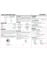
INSTALLATION INSTRUCTIONS
Description:
The passive infrared sensors work by detecting the difference between heat emitted from the human body in motion and the background space.
The sensor switch can turn a load ON and hold it as long as the sensor detects occupancy. After no motion is detected for the set time delay, the
load turns OFF automatically. The sensor switch has one relay (equal to single pole switch), it also includes Ambient Light Level Sensor.
Coverage Area:
The coverage range of the sensor switch is specified and illustrated in Figure 1. Large objects and some transparent barriers like glass windows
will obstruct the sensor’s view and prevent detection, causing the light to turn off even though someone is still in the detection area.
LOCATION/MOUNTING
Since this device responds to temperature changes, care should be taken when mounting the device. DO NOT mount directly above a heat source,
in a location where hot or cold drafts will blow directly on the sensor, or where unintended motion will be within sensor’s field-of-view.
INSTALLATION
1. Remove existing single pole switch or dimmer installation, if applicable.
2. Remove 3/4: (1.9 cm) of insulation from each circuit conductor. Make sure the ends of wires are straight.
3. Connect lead wires as shown in WIRING DIAGRAM (see Figure 2): Black lead to Line (Hot), Red lead to Load wire, White lead to Neutral wire,
Green lead to Ground.
4. Gently position wires in wall box, attach sensor switch to the box.
5. Mount device “TOP” up.
6. Restore power at circuit breaker or fuse, wait one minute.
7. Remove the small cover plate. (Illustrated as Figure 3.)
8. Locate the adjustment knobs on the control panel to perform test. and adjustments. (Illustrated as Figure 4.)
9. Replace the small cover plate after testing and adjusting.
10. Attach the wallplate.
NOTE: If twist on wire connector is provided, use to join one supply conductor with one 16 AWG device control lead.
ADJUSTMENT
Band Switch
Time Delay Knob
Default position: 15 Seconds (Test mode)
Adjustable: from 15 Seconds to 30 Minutes (clockwise)
Sensor Sensitivity Range Knob
Default position: Center at 65%
Adjustable: 30% (Position 1) to 100% (Position 4)
Note: Turn clockwise for larger rooms. Turn counter clockwise to avoid false alerts in smaller rooms or near doorway or
heat source.
Ambient Light Dial: The ambient light setting is adjusted with the Ambient Light dial (refer to figure 4). Turning the Light
Dial fully counter clockwise (CW), lights always turn ON, when the motion is detected. All other settings will cause the
lights to turn ON only when the light level is less than the setting.
Default position: Daylight (100% at position 4)
Adjustable: Daylight to 39 Lux (Counter clockwise)
OPERATION
The Sensor Switch is programmed independently for either Occupancy Mode or Vacancy Mode as referred to the Band
Switch position under the control panel cover. Vacancy mode is also known as “Manual On Occupancy Mode”. By pushing
the Control Panel Cover, the load can be turned On/Off under either OCC or VAC mode. (Illustrated as Figure 5)
Turning On the load under Occupancy Mode
Load to be Automatic ON once occupancy is detected.
Turning On the load under Vacancy Mode
Manual ON/OFF Button has to be pushed to turn ON the Load.
Automatic Turning Off the load
Under either mode, the Sensor keeps the Load On until no motion is detected or the set time delay, load(s) to be Off
automatically. Under VAC Mode, the Load can turn On automatically if motion is detected within the 1st 30 seconds.
Manual Turning Off the Load
By Manual ON/OFF Button, the Load can be turned OFF under either OCC or VAC mode. Under OCC Mode, the Load cannot
automatically turn ON 5 mins after the last motion is detected.
Neutral
White
Hot
Black
Ground
Green
Load
Red
Neutral(White)
Load
Occupancy / Vacancy
(2-IN-1)
Sensor Switch
MODEL: IOS-DOV
Ratings:
Incandescent / Tungsten: 800W-120VAC
Resistive load: 800W-120VAC
Fluorescent / Ballast: 800VA-120VAC
Motor: 1/4HP-120VAC
Time Delay: 15 Sec to 30 Min
Light Level: 30 Lux--Daylight
Operation Temperature: 32˚F--131˚F / 0-55˚C
No minimum Load required.
Figure 1
Figure 3
Wiring Diagram
Maximum: 1200 sq.ft.
40'
Top View
20'
10'
20'
10'
20'
5'
4'
180˚ Field of View
Figure 2
Figure 4
Figure 5
IOS-DOV/IOS-DOV-NL
Risk of Fire, Electrical Shock or Personal Injury
• TurnOFFpoweratcircuitbreakerorfuseandtestthatthepowerisOFFbeforewiring.
• Tobeinstalledand/orusedinaccordancewithappropriateelectricalcodesandregulations.
• Ifyouarenotsureaboutanypartoftheseinstructions,consultaqualiedelectrician.
• Usethisdeviceonlywithcopperorcoppercladwire.
• INDOOR USE ONLY
WARNING
Mode Position Description React to the pushbutton
OFF LEFT Circuit is permanently opened None
OCC Center Occupancy Mode:
Automatic ON automatic OFF after set
time delay.
Manually toggles ON/OFF
the load.
VAC RIGHT Vacancy Mode: Manual ON only auto-
matic OFF after set time delay
Manually toggles ON/OFF
the load.

TROUBLESHOOTING
For proper operation, the Sensor Switch has to consume power from hot and Neutral. Therefore, Secured Neutral Wires are required.
Initial run
The Sensor Switch needs initial run within one minute. During the initial run, the load might be turned On and Off several times.
The Time Delay knob is set to 15 seconds default, do not adjust it until initial run is finished and proper operation function is confirmed.
The load is flashing frequently.
1. It can take up to one minute for initial run.
2. Check the wiring connections, especially the Neutral Wire.
The Load does not turn ON without LED flashing or LED flashing regardless of motion.
1. Push Manual On/Off Button, if the load turns On; verify that Sensitive Range is on high. If the Load does not turn ON, go to Step 2.
2. Check the wiring connections, especially Hot line and Neutral wire.
The Load does not turn ON while LED is flashing and motion is detected
1. Check to see if Ambient Light Level is enabled by covering the lens by hand.
2. Push Manual On/Off Button, if the load turns On; verify that Sensitivity Range is on high. If the Load does not turn On, go to Step 3.
3. Check the wiring connections, especially Hot Line and Neutral wire.
The Load does not turn Off
1. There can be up to a 30 minute time delay after the last motion is detected. To verify proper operation, turn the Time Delay Knob to 15s (Test Mode), make sure there is no motion (no LED flashing), the Load should turn Off in 15 seconds.
2. Check if there are any significant heat sources mounted within six feet (two meters) that may cause false detection such as, high wattage light bulb, portable heater or HVAC device.
3. Check the wiring connections, especially the Neutral wire to the sensor switch.
The Load turns On unintentionally
1. Switch from OCC to VAC mode.
2. Mask the Sensor Switch’s lens to eliminate unwanted coverage area.
3. Turn the Sensitivity Level knob counter-clockwise to avoid false alerts in smaller rooms or near doorway.
NOTE: If problems continue, consult a qualified electrician.
RESOLUCIÓN DE PROBLEMAS
Para una operación correcta, el Interruptor Sensor tiene que consumir electricidad de cables Calientes y Neutros. Por lo tanto, se requieren Cables Conectados a Tierra.
Pasada Inicial
El Interruptor Sensor necesita una pasada inicial en el primer minuto. Durante la pasada inicial, la carga se puede Encender y Apagar varias veces.
La perilla de Retardo tiene una configuración predeterminada de 15 segundos, no ajustarla hasta completar la pasada inicial y confirmar que el funcionamiento sea correcto.
La carga titila frecuentemente.
1. Puede llevar hasta un minuto para la pasada inicial.
2. Controle las conexiones de cableado, en especial el Cable Neutro.
La Carga no se ENCIENDE sin que el LED titile o el LED titila sin importar el movimiento.
1. Presione el botón de Encendido/Apagado Manual: si la carga se Enciende, verifique que el Rango de Sensibilidad esté colocado en alto. Si la Carga no se ENCIENDE, pase el Paso 2.
2. Controle las conexiones de cableado, en especial la línea Caliente y el cable Neutro.
La Carga no se ENCIENDE mientras el LED titila y se detecta movimiento
1. Controle que el Nivel de Luz Ambiente esté habilitado cubriendo el lente con la mano.
2. Presione el botón de Encendido/Apagado Manual: si la carga se Enciende, verifique que el Rango de Sensibilidad esté colocado en alto. Si la Carga no se Enciende, pase el Paso 3.
3. Controle las conexiones de cableado, en especial la Línea Caliente y el cable Neutro.
La Carga no se Apaga
1. Puede haber un retardo de hasta 30 minutos después de que se detecta el último movimiento. Para verificar que el funcionamiento sea correcto, coloque la Perilla de Retardo en 15s (Modo de Prueba) y asegúrese de que no haya movimiento (el LED no titila);
la Carga debe Apagarse en 15 segundos.
2. Controle que no haya ninguna fuente significativa de calor montada a menos de seis pies (dos metros), ya que esto puede provocar una detección falsa como una bombilla de luz de alta potencia, un calentador portátil o un dispositivo HVAC (de climatización).
3. Controle las conexiones de cableado, en especial el cable Neutro hasta el interruptor sensor.
La Carga se Enciende de manera no intencional
1. Pase de modo OCC a VAC.
2. Encinte la lente del Interruptor Sensor para eliminar área de cobertura no deseada.
3. Gire la perilla de Nivel de Sensibilidad en sentido antihorario para evitar alertas falsas en salas más pequeñas o cerca de una puerta.
NOTA: Si los problemas persisten, consulte a un electricista calificado.
DÉPANNAGE
Pour fonctionner correctement, le contacteur de détection doit consommer du courant d’un fil chargé et neutre. Par conséquent, un fil neutre protégé est requis.
Première mise en marche
Le contacteur de détection a besoin d’une première mise en marche dans la minute qui suit. Pendant la première mise en marche, la charge peut s’activer et se désactiver plusieurs fois.
Le bouton de temporisation est réglé à 15 secondes par défaut, ne pas l’ajuster avant d’avoir terminé la première mise en marche et la confirmation d’un fonctionnement correct.
La charge clignote fréquemment.
1. Jusqu’à une minute peut être nécessaire pour la première mise en marche.
2. Vérierlesconnexionsducâblage,particulièrementlefil neutre.
La charge ne s’active pas sans que le clignotement du DEL ou clignotement du DEL peu importe le mouvement.
1. Pousser manuellement le bouton d’activation, si la charge s’active; vérifier que la plage de sensibilité est à élevée. Si la charge ne s’active pas, passer à l’étape 2.
2. Vérierlesconnexionsducâblage,particulièrementlalignesoustensionetlelneutre.
La charge ne s’active pas alors que le DEL clignote et qu’un mouvement est détecté
1. Vérifier si l’intensité lumineuse ambiante est activée en couvrant les lentilles avec la main.
2. Pousser manuellement le bouton d’activation, si la charge s’active; vérifier que la plage de sensibilité est à élevée. Si la charge ne s’active pas, passer à l’étape 3.
3. Vérierlesconnexionsducâblage,particulièrementlalignesoustensionetlelneutre.
La charge ne se désactive pas
1. Il peut y avoir jusqu’à 30 minutes de délai après la détection du dernier mouvement. Afin de vérifier le bon fonctionnement, mettre le bouton de temporisation à 15 s (mode essai), s’assurer qu’il n’y a pas de mouvement (aucun clignotement DEL), la charge
devrait se désactiver après 15 secondes.
2. Vérifier s’il y a une source de chaleur importante installée à moins de six pieds (deux mètres), ceci pourrait causer une fausse détection, notamment, une ampoule à grande puissance, une chaufferette portable ou un appareil de CVCA.
3. Vérierlesconnexionsducâblage,particulièrementlecâbleneutreaucontacteurdedétection.
La charge s’allume de manière imprévue
1. Passer du mode OCC à VAC.
2. Masquer la lentille du contacteur de détection pour éliminer une zone de couverture non voulue.
3. Tourner le bouton de degré de sensibilité dans le sens antihoraire pour éviter les fausses alertes dans les pièces plus petites ou près des entrées de porte.
REMARQUE: Si le problème persiste, vous adresser à un électricien qualifié.
LIMITED FIVE YEAR WARRANTY
If within the warranty period specified, this product fails due to a defect in material or workmanship, Intermatic Incorporated will repair or replace it, at its sole option, free of charge. This warranty is extended to the original
purchaser only and is not transferable. This warranty does not apply to: (a) damage to units caused by accident, dropping or abuse in handling, acts of God or any negligent use; (b) units which have been subject to
unauthorized repair, opened, taken apart or otherwise modified; (c) units not used in accordance with instructions; (d) damages exceeding the cost of the product; (e) sealed lamps and/or lamp bulbs, LED’s and
batteries; (f) the finish on any portion of the product, such as surface and/or weathering, as this is considered normal wear and tear; (g) transit damage, initial installation costs, removal costs, or reinstallation costs.
INTERMATIC INCORPORATED WILL NOT BE LIABLE FOR INCIDENTAL OR CONSEQUENTIAL DAMAGES. SOME STATES DO NOT ALLOW THE EXCLUSION OR LIMITATION OF INCIDENTAL OR
CONSEQUENTIAL DAMAGES, SO THE ABOVE LIMITATION OR EXCLUSION MAY NOT APPLY TO YOU. THIS WARRANTY IS IN LIEU OF ALL OTHER EXPRESS OR IMPLIED WARRANTIES. ALL IMPLIED
WARRANTIES, INCLUDING THE WARRANTY OF MERCHANTABILITY AND THE WARRANTY OF FITNESS FOR A PARTICULAR PURPOSE, ARE HEREBY MODIFIED TO EXIST ONLY AS CONTAINED IN THIS
LIMITED WARRANTY, AND SHALL BE OF THE SAME DURATION AS THE WARRANTY PERIOD STATED ABOVE. SOME STATES DO NOT ALLOW LIMITATIONS ON THE DURATION OF AN IMPLIED
WARRANTY, SO THE ABOVE LIMITATION MAY NOT APPLY TO YOU.
This warranty service is available by either (a) returning the product to the dealer from whom the unit was purchased, or (b) completing a warranty claim on line at www.intermatic.com. This warranty is made by:
Intermatic Incorporated, Customer Service 7777 Winn Rd. Spring Grove, Illinois 60081-9698. For warranty service go to: http://www.intermatic.com or call 815-675-7000.
GARANTÍA LIMITADA DE CINCO AÑOS
Si dentro del período de garantía especificado este producto falla debido a un defecto de material o de mano de obra, Intermatic Incorporated lo reparará o reemplazará, a su entera discreción, sin cargo alguno. Esta garantía sólo se otorga al
comprador original y no es transferible. Esta garantía no se aplica en los siguientes casos: (a) daños en las unidades causados por accidentes, caídas o manejo indebido, causas de fuerza mayor o uso negligente; (b) unidades que hayan sido
sometidas a una reparación no autorizada, abiertas, desmontadas o modificadas de alguna manera; c) unidades no utilizadas de acuerdo con las instrucciones; (d) daños que excedan el costo del producto; (e) lámparas y/o bombillas de lámparas
selladas, diodos emisores de luz (LED) y baterías; (f) el acabado de cualquier parte del producto, como su superficie y/o por exposición a la intemperie, ya que esto se considera un desgaste y uso normal; g) daños durante el transporte, costos de
instalación inicial, costos de remoción o costos de reinstalación.
INTERMATIC INCORPORATED NO ASUME RESPONSABILIDAD ALGUNA POR DAÑOS INCIDENTALES O CONSECUENCIALES. ALGUNOS ESTADOS NO PERMITEN EXCLUIR O LIMITAR LOS DAÑOS INCIDENTALES O CONSECUENCIALES, POR LO QUE LA
LIMITACIÓN O EXCLUSIÓN ANTERIOR PUDIERA NO SER VÁLIDA EN SU CASO. ESTA GARANTÍA SUSTITUYE A CUALQUIER OTRA GARANTÍA EXPRESA O IMPLÍCITA. TODAS LAS GARANTÍAS IMPLÍCITAS, INCLUIDA LA GARANTÍA DE IDONEIDAD COMERCIAL O
DE IDONEIDAD PARA UN DETERMINADO FIN, SE MODIFICAN PARA QUEDAR INCLUIDAS ÚNICAMENTE EN LA PRESENTE GARANTÍA LIMITADA, Y TENDRÁN LA MISMA DURACIÓN QUE EL PERIODO DE GARANTÍA MENCIONADO ANTES. ALGUNOS ESTADOS NO
PERMITEN LIMITAR LA DURACIÓN DE UNA GARANTÍA IMPLÍCITA, POR LO QUE LA LIMITACIÓN ANTERIOR PUDIERA NO SER APLICABLE EN SU CASO.
Este servicio de garantía está disponible (a) devolviendo el producto al distribuidor donde se compró la unidad o (b) completando un reclamo de garantía en Internet en www.intermatic.com. Esta garantía es concedida por: Intermatic Incorporated
Customer Service/7777 Winn Rd., Spring Grove, Illinois 60081-9698/815-675-7000 http://www.intermatic.com
GARANTIE LIMITÉE DE CINQ ANS
Si, au cours de la période indiquée, ce dispositif présente une défectuosité de matériel ou de fabrication, Intermatic Incorporated s’engage à le réparer ou le remplacer, à sa seule discrétion, sans frais. Cette garantie s’applique uniquement à
l’acheteur original et elle est incessible. Cette garantie ne s’applique pas : (a) aux dommages au dispositif causés par un accident, une chute ou une mauvaise manipulation, une catastrophe naturelle ou une utilisation négligente ; (b) aux dispositifs
soumis à des réparations non autorisées, qui ont été ouverts, démontés ou modifiés de quelconque manière ; (c) aux dispositifs qui n’ont pas été utilisés selon les directives ; (d) aux dommages dépassant le coût du produit ; (e) aux lampes scellées
et/ou aux ampoules, aux DEL et aux piles ; (f) à la finition de l’une des parties du dispositif, telle que la surface ou les caractéristiques de résistance aux intempéries, ce qui est considéré comme de l’usure normale ; (g) aux dommages causés par le
transport, aux coûts d’installation initiale, aux coûts de démontage ou de remontage.
INTERMATIC INCORPORATED NE POURRA ÊTRE TENUE RESPONSABLE DE DOMMAGES ACCIDENTELS OU CONSÉCUTIFS. CERTAINS ÉTATS N’AUTORISENT PAS L’EXCLUSION OU LA LIMITATION DE DOMMAGES ACCIDENTELS OU CONSÉCUTIFS. DANS CE
CAS, LES LIMITES CI-DESSUS NE S’APPLIQUENT PAS. CETTE GARANTIE REMPLACE TOUTES LES AUTRES GARANTIES EXPRESSES OU IMPLICITES. TOUTES LES GARANTIES IMPLICITES, Y COMPRIS LA GARANTIE DE COMMERCIALISATION ET LA GARANTIE
DECONFORMITÉÀUNEFINPRÉVUE,SONTPARLAPRÉSENTEMODIFIÉESPOUREXISTERUNIQUEMENTTELLESQUECOMPRISESDANSLAGARANTIELIMITÉE,ETAURONTLAMÊMEDURÉEQUELAPÉRIODEDEGARANTIEDÉCLARÉECI-DESSUS.
CERTAINS ÉTATS N’ACCEPTENT PAS DE LIMITES SUR LA DURÉE D’UNE GARANTIE IMPLICITE. DANS CE CAS, LA LIMITE PEUT NE PAS VOUS CONCERNER.
Le service de garantie est disponible soit (a) par retour du produit au vendeur auprès duquel le dispositif a été acheté soit (b) en remplissant le formulaire de réclamation sur le site Web www.intermatic.com. Cette garantie est accordée par :
Intermatic Incorporated / 7777 Winn Rd., Spring Grove, Illinois 60081-9698 / 815-675-7000 http://www.intermatic.com
158--01246
/


