Page is loading ...

1
ACDC Motorized Solutions Pty. Ltd.
RollerGlide Rolling Door Operator
Owner manual
Congratulations on the purchase of a RollerGlide rolling door operator, this quality
product is designed to provide years of trouble free service
Operation
Two remotes controls are supplied
An optional fixed push button can be used
With each press of the button the door will open, stop or close
The courtesy light switches on for several minutes when the door is operated
Auto-Close
The Auto-Close feature can be selected to close the door automatically after 45
seconds
Safety
Timers are provided to stop the motor if it operates longer than the required time
The power transformer contains a thermal overload device to prevent the transformer
from overheating and causing a fire
The door should only be operated when it can be observed to avoid accidents
Emergency stopping
The RollerGlide will stop and reverse if the door is obstructed or jammed when
closing and will stop if the door is jammed when opening. The obstruction force
setting must be set correctly for the function to operate properly.
Manual operation
The RollerGlide can be set for manual operation by pulling the service lever this
could be required if no power is available and the door has to be opened or closed
Open and Close limits
The RollerGlide is adjustable to stop the door at the correct place in both open and
closed positions
Adding extra remote controls (see figure 3)
Remove the white plastic light diffuser – beware of connected Push button
attached.
• Press the LEARN button on the control panel
• Press one of the buttons on the remote control which you wish to use
• Wait a few seconds and press the same remote button again
• To erase existing remote controls press and hold the LEARN button for 15
seconds
• Up to 25 remote controls may be used
Other products available
Check our Website http://www.acdcms.com.au

2
ACDC Motorized Solutions Pty. Ltd.
RollerGlide Rolling Door Operator
Installer fitting instructions
Introduction
If this is your first installation of a RollerGlide automatic rolling door operator, please
read and fully understand the instructions before proceeding. For more information
and product updates visit our Web site http://www.acdcms.com.au.
Check contents in the installation kit
RollerGlide automatic rolling door operator
Power lead
Two remote transmitters
Owner manual & Warning label
Extension forks & weight bars (x2)
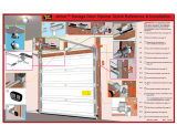
Tools required (see figure 1)
Extension socket set, to fit the existing U-bolts on the door
• A 14mm spanner or socket to tighten the RollerGlide bolts
• Door support or prop
• A ladder to reach the top of the door
• Rope or strap to secure door curtain
• Lifting bar (piece of strong steel pipe) to fit inside the door support shaft to aid
lifting
• Small bladed screwdriver to adjust internal controls
• Use a helper if possible to assist with the installation
Checks (see figure 1)
• The door must be in good working order
• Some doors require the fitting of a weight bar that sits in the bottom of the
door to provide a small amount of extra weight; this stabilizes the bottom of
the door when closing and provides inertia to allow the door to fully close.
They are usually a rectangular length of mild steel weighing about 2kg
• Tighten the U-bolt clamp on the opposite end to where the RollerGlide is to
be installed
• All existing door locks should be removed or warranty will be void
• The RollerGlide is fitted between the door mounting bracket and the door
roller. The minimum distance needed is 70mm. If the distance is not sufficient
the mounting bracket may need to be adjusted.
• The unit is shipped to fit a right hand installation
(Viewed from inside the garage)
• Use the service lever to disengage the unit so that the large fork wheel freely
rotates
• Changing from right to left mounting (see figure 3)
• The motor power plug is moved from socket A to socket B changing the
operator from right to left hand operation

3
ACDC Motorized Solutions Pty. Ltd.
RollerGlide Rolling Door Operator
Installer fitting instructions…. continued
Fitting (see figure 1)
• Open the door and tie a rope or strap around to prevent it unrolling
• Support the door underneath by a door prop or similar to take the weight, use
padding to prevent damaging the door
• Remove the U-bolt clamp from the fitting side
• If space permits use the metal pipe to assist lifting the door by inserting it into
the door support shaft
• Lift and move the roller door shaft and slide on the RollerGlide to fit between
the bracket and the roller door
• Rotate the drive fork wheel and position its forks to engage the roller door
drum wheel
• Refit the original U-bolt clamp
• Align the RollerGlide in a vertical position and tighten its locking bolts
• After a final check remove the rope and door support prop
Setting limit switches by manually positioning the door (see figure 2)
• Limit switches are needed to stop the door at the correct open and closed
positions
• Remove the power, disengage the RollerGlide with the service lever and fully
open the door
• Turn the green cam wheel anti-clockwise until its limit switch clicks
• Close the door
• Turn the red cam wheel clockwise until its limit switch clicks.
• The matching coloured adjusting bolts are used for fine adjustment one turn is
about 10mm of door movement
• Accurate adjustment is needed to minimize noise and wear on the unit
Setting limit switches via control panel (see figure 3)
• With power on the open and close controls can be used to move the door
• When using the control panel open and close controls, the obstruction system
is disabled. Don’t allow the door to open or close beyond its end positions
or the RollerGlide may be forced out of position or even damaged, and
warranty will be viod.
Remote control operation (see figure 3)
• Operate the door with the remote control by pressing the remote button. The
door will open or close or stop each time the button is pressed
• Run the door up and down and finely adjust for the correct open and closed
positions by using the coloured adjusting bolts
• Should the remote not work see Adding Extra Remote Controls (page 1)

4
ACDC Motorized Solutions Pty. Ltd.
RollerGlide Rolling Door Operator
Installer fitting instructions…. continued
Setting obstruction force (see figure 3)
This facility is provided to stop the door when it encounters an obstruction or jambs.
For each installation the obstruction force setting must be adjusted. Failure to do
this correctly may cause serious injury or damage, and will void any warranty.
• Screwdriver adjustments are made on the blue control panel located on the
control board
• Use the remote control (or optional fixed push button) to operate the door
when setting these controls
• To test the obstruction force, press the remote control (or optional fixed push
button) to close the door
• Obstruct the door by holding it at the bottom, this will cause it to stop and
reverse
• For the obstruction sensing to detect an object in the door way, some force will
be applied to the object which may suffer damage or injury to the object,
person and/or door.
• Set this for the required force with the close force adjusting control
• The open force is set by holding the door when it is opening; this time the door
will just stop
• Periodic maintenance is required to maintain optimum performance. The
obstruction force may need to be re-adjusted in the future as the door ages.
Auto-Close (see figure 3)
This feature allows the door to close automatically 45 seconds after it opens
Photo Electric Safety Beams must be fitted to use this feature as a practical
necessity and to conform to required regulations. A safety circuit is provided for
this purpose see photoelectric beam section on this page.
This option is selected by moving the link on plug J1 located at the middle top of the
control board
J1 has 3 pins the off position links the centre pin to OFF. The on position links the
centre position to ON. (Normal factory setting is OFF)
Manual push button (see figure 3)
If required a normally open push button can be connected to the screw terminals
CO and BT located at the centre bottom of the control board on terminal block X4
Photoelectric beam (see figure 3)
• Use screw terminal +24 and 0V for the detector 24volts power
• Remove the link from CO & IR and connect the photoelectric detector switch
to these terminals. This switch must be closed when operating normally and
should open when the beam is broken
• The screw terminals are located at the bottom on the controller board on
terminal block X4

5
ACDC Motorized Solutions Pty. Ltd.
RollerGlide Rolling Door Operator
Figure 1
Figure 2
Coarse Cam Colour Fine Bolt
Open A Green Open B
Close C Red Close D

6
FIGURE 3
RollerGlide Electronic Controller
1. Motor direction, change plug as needed
A = Right side installation B = Left side installation
2. Auto-Close, move the link on J1 as needed
ON Off
1 link 1
2 link 2 link
3 3 link
Auto-Close uses a safety circuit requiring a link to be connected
between CO and IR on the terminal block (X4)
3. Remote control, add and erase push button
4. Open and close controls
5. Obstruction force controls
6. Terminal Block (X4)
Tag Function External device
+24 24V DC output *photoelectric detector
0V 24V DC output photoelectric detector
CO Ground *Manual switch, normally open
BT Input Manual switch
CO Ground photoelectric detector, normally closed
IR Input photoelectric detector
*Photoelectric detector
Remove the safety link from CO and IR
Connect to power +24 and 0V, the switch to CO and IR
The detector must provide a closed circuit that opens when beam is broken
*Optional fixed door control switch
Connect to CO and BT, the switch is normally open, closing when pressed

7
ACDC Motorized Solutions Pty. Ltd.
RollerGlide Rolling Door Operator
RollerGlide Specifications
Manufactured to ISO 9001
Electrical
Power fuse: 1A 240V
Power supply: 240V AC 50HZ 100W
Power input: Standard power socket with unplugable lead
Power transformer: Output 24V AC with thermal overload protection
Courtesy light: 15W/240V
Motor: High torque 24V DC with enclosed Hall Effect sensor
Mechanical
Overhead height: 3.0m (maximum)
Width: 5.0m (maximum)
Suitability: Spring balanced roller doors
Maximum lifting capacity: 250N
Reel diameter: 270mm
Operating speed: 8m/min
Weight of main unit: 7.5Kg
Dimension: 200×260×480mm
Controls
Service lever for manual operation during power disruption
Two encoded wireless remote controls
Provision for using a press button switch
Photoelectric power connection and input, fail-safe
Adjustable bi-directional obstruction detection
Adjustable open and close fail-safe limit switches
Service help
Following this guide may resolve your service problem
Obvious problems are not included.
Door won’t open/close fully
If the door fails to fully open or close fully it may be jammed, pull the service lever to
disengage the motor drive and operate the door manually to check.
If the opening or closing error is only a small distance it may require the limit switches
to be adjusted see Setting limit switches (page 3)
Not operating with the remote control.
Try a second remote control and if still not working remove the white plastic light
diffuser and operate it with the control panel buttons located on the blue control panel
at the bottom of the control board.
If this operates correctly erase the existing remote controls and add them again
See page 1 Adding extra remote controls
Rev.1 March 2008
/


