
DVD Receiver
DR-S2.0
Instruction Manual
Thank you for purchasing the Onkyo DVD Receiver.
Please read this manual thoroughly before making
connections and turning on the power.
Following the instructions in this manual will enable
you to obtain optimum performance and listening
enjoyment from your new DVD Receiver.
Please retain this manual for future reference.
Contents
Getting Started
Basic Operation
Before Using Your DVD Receiver 2
Other
Additional Operation
Advanced DVD/VIDEO CD/
Audio CD Operation

2
Important Safeguards
1. Read Instructions – All the safety and operating instructions
should be read before the appliance is operated.
2. Retain Instructions – The safety and operating instructions
should be retained for future reference.
3. Heed Warnings – All warnings on the appliance and in the
operating instructions should be adhered to.
4. Follow Instructions – All operating and use instructions should
be followed.
5. Cleaning – Unplug the appliance from the wall outlet (the
mains) before cleaning. The appliance should be cleaned only
as recommended by the manufacturer.
6. Attachments – Do not use attachments not recommended by
the appliance manufacturer as they may cause hazards.
7. Water and Moisture – Do not use the appliance near water –for
example, near a bath tub, wash bowl, kitchen sink, or laundry
tub; in a wet basement; or near a swimming pool; and the like.
8. Accessories – Do not place the appliance on an unstable cart,
stand, tripod, bracket, or table. The appliance may fall, causing
serious injury to a child or adult, and serious damage to the
appliance. Use only with a cart, stand, tripod, bracket, or table
recommended by the manufacturer, or sold with the appliance.
Any mounting of the appliance should follow the manufacturer’s
instructions, and should use a mounting accessory
recommended by the manufacturer.
9. An appliance and cart combination should
be moved with care. Quick stops,
excessive force, and uneven surfaces
may cause the appliance and cart
combination to overturn.
10. Ventilation – Slots and openings in the cabinet are provided for
ventilation and to ensure reliable operation of the appliance and
to protect it from overheating, and these openings must not be
blocked or covered. The openings should never be blocked by
placing the appliance on a bed, sofa, rug, or other similar
surface. The appliance should not be placed in a built-in
installation such as a bookcase or rack unless proper ventilation
is provided. There should be free space of at least 20 cm (8 in.)
and an opening behind the appliance.
11. Power Sources – The appliance should be operated only from
the type of power source indicated on the marking label. If you
are not sure of the type of power supply to your home, consult
your appliance dealer or local power company.
12. Grounding or Polarization – The appliance may be equipped
with a polarized alternating current line plug (a plug having one
blade wider than the other). This plug will fit into the power outlet
only one way. This is a safety feature. If you are unable to insert
the plug fully into the outlet, try reversing the plug. If the plug
should still fail to fit, contact your electrician to replace your
obsolete outlet. Do not defeat the safety purpose of the
polarized plug.
13. Power-Cord Protection – Power-supply cords (mains leads)
should be routed so that they are not likely to be walked on or
pinched by items placed upon or against them, paying particular
attention to cords (leads) at plugs, convenience receptacles, and
the point where they exit from the appliance.
14. Outdoor Antenna (Aerial) Grounding – If an outside antenna (aerial)
or cable system is connected to the appliance, be sure the antenna
(aerial) or cable system is grounded so as to provide some protection
against voltage surges and built-up static charges. Article 810 of the
National Electrical Code, ANSI/NFPA 70, provides information with
regard to proper grounding of the mast and supporting structure,
grounding of the lead-in wire to an antenna- (aerial-) discharge unit,
size of grounding conductors, location of antenna- (aerial-) discharge
unit, connection to grounding electrodes, and requirements for the
grounding electrode. See FIGURE 1.
15. Lightning – For added protection for the appliance during a
lightning storm, or when it is left unattended and unused for long
periods of time, unplug it from the wall outlet (the mains) and
disconnect the antenna (aerial) or cable system. This will prevent
damage to the appliance due to lightning and power-line surges.
16. Power Lines – An outside antenna (aerial) system should not be
located in the vicinity of overhead power lines or other electric light or
power circuits, or where it can fall into such power lines or circuits.
When installing an outside antenna (aerial) system, extreme care
should be taken to keep from touching such power lines or circuits as
contact with them might be fatal.
17. Overloading – Do not overload wall outlets, extension cords
(leads), or integral convenience receptacles as this can result in a
risk of fire or electric shock.
18. Object and Liquid Entry – Never push objects of any kind into the
appliance through openings as they may touch dangerous voltage
points or short-out parts that could result in a fire or electric shock.
Never spill liquid of any kind on the appliance.
19. Servicing – Do not attempt to service the appliance yourself as
opening or removing covers may expose you to dangerous voltage
or other hazards. Refer all servicing to qualified service personnel.
20. Damage Requiring Service – Unplug the appliance form the wall
outlet (the mains) and refer servicing to qualified service personnel
under the following conditions:
A. When the power-supply cord (mains lead) or plug is damaged,
B. If liquid has been spilled, or objects have fallen into the
appliance,
C. If the appliance has been exposed to rain or water,
D. If the appliance does not operate normally by following the
operating instructions. Adjust only those controls that are
covered by the operating instructions as an improper
adjustment of other controls may result in damage and will often
require extensive work by a qualified technician to restore the
appliance to its normal operation,
E. If the appliance has been dropped or damaged in any way, and
F. When the appliance exhibits a distinct change in performance –
this indicates a need for service.
WARNING:
TO REDUCE THE RISK OF FIRE OR ELECTRIC
SHOCK, DO NOT EXPOSE THIS APPLIANCE
TO RAIN OR MOISTURE.
CAUTION:
TO REDUCE THE RISK OF ELECTRIC SHOCK,
DO NOT REMOVE COVER (OR BACK).
NO USER-SERVICEABLE PARTS INSIDE.
REFER SERVICING TO QUALIFIED SERVICE
PERSONNEL.
The lightning flash with arrowhead
symbol, within an equilateral triangle, is
intended to alert the user to the presence
of uninsulated “dangerous voltage” within
the product’s enclosure that may be of
sufficient magnitude to constitute a risk of
electric shock to persons.
The exclamation point within an
equilateral triangle is intended to alert the
user to the presence of important
operating and maintenance (servicing)
instructions in the literature accompanying
the appliance.
RISQUE DE CHOC ELECTRIQUE
NE PAS
OUVRIR
AVIS
RISK OF ELECTRIC SHOCK
DO NOT OPEN
WARNING
S3125A
PORTABLE CART WARNING

3
GROUND
CLAMP
ELECTRIC
SERVICE
EQUIPMENT
POWER SERVICE GROUNDING
ELECTRODE SYSTEM
(NEC ART 250, PART H)
GROUND CLAMPS
GROUNDING CONDUCTORS
(NEC SECTION 810-21)
ANTENNA
DISCHARGE UNIT
(NEC SECTION 810-20)
ANTENNA
LEAD IN
WIRE
NEC – NATIONAL ELECTRICAL CODE
S2898A
21. Replacement Parts – When replacement parts are required, be
sure the service technician has used replacement parts
specified by the manufacturer or have the same characteristics
as the original part. Unauthorized substitutions may result in
fire, electric shock, or other hazards.
22. Safety Check – Upon completion of any service or repairs to
the appliance, ask the service technician to perform safety
checks to determine that the appliance is in proper operation
condition.
23. Wall or Ceiling Mounting – The appliance should be mounted
to a wall or ceiling only as recommended by the manufacturer.
24. Heat – The appliance should be situated away from heat
sources such as radiators, heat registers, stoves, or other
appliances (including amplifiers) that produce heat.
FIGURE 1:
EXAMPLE OF ANTENNA (AERIAL) GROUNDING AS PER NATIONAL
ELECTRICAL CODE, ANSI/NFPA 70
CAUTION:
VISIBLE LASER RADIATION WHEN OPEN AND INTERLOCK
FAILED OR DEFEATED. DO NOT STARE INTO BEAM.
CAUTION:
THIS PRODUCT UTILIZES A LASER. USE OF CONTROLS OR
ADJUSTMENTS OR PERFORMANCE OF PROCEDURES
OTHER THAN THOSE SPECIFIED HEREIN MAY RESULT IN
HAZARDOUS RADIATION EXPOSURE.
This unit contains a semiconductor laser system and is classified
as a “CLASS 1 LASER PRODUCT.” So, to use this model properly,
read this Instruction Manual carefully. In case of any trouble, please
contact the store where you purchased the unit. To prevent being
exposed to the laser beam, do not try to open the enclosure.
Precautions
“CLASS 1 LASER
PRODUCT”
This label on the rear panel states that:
1. This unit is a CLASS 1 LASER PRODUCT and employs a
laser inside the cabinet.
2. To prevent the laser from being exposed, do not remove the
cover. Refer servicing to qualified personnel.
For Canadian model
This class B digital apparatus complies with Canadian ICES-003.
For models having a power cord with a polarized plug:
CAUTION: TO PREVENT ELECTRIC SHOCK, MATCH WIDE
BLADE OF PLUG TO WIDE SLOT, FULLY INSERT.
Modele pour les Canadien
Cet appareil numérique de la classe B est conforme à la norme
NMB-003 du Canada.
Sur les modeles dont la fiche est polarisee:
ATTENTION: POUR EVITER LES CHOCS ELECTRIQUES,
INTRODUIRE LA LAME LA PLUS LARGE DE LA FICHE DANS LA
BORNE CORRESPONDANTE DE LA PRISE ET POUSSER
JUSQU’AU FOND.
For U.S. model
The laser is covered by a housing which prevents exposure during
operation or maintenance. However, this product is classified as a
Laser Product by CDRH (Center for Devices and Radiological
Health) which is a department of the Food and Drug Administration.
According to their regulations 21 CFR section 1002.30, all
manufactures who sell Laser Products must maintain records of
written communications between the manufacturer, dealers and
customers concerning radiation safety. If you have any complaints
about instructions or explanations affecting the use of this product,
please feel free to write to the address on the back page of this
manual. When you write us, please include the model number and
serial number of your unit.
In compliance with Federal Regulations, the certification,
identification and the period of manufacture are indicated on the rear
panel.
FCC INFORMATION FOR USER
CAUTION:
The user changes or modifications not expressly approved by the
party responsible for compliance could void the user’s authority to
operate the equipment.
NOTE:
This equipment has been tested and found to comply with the limits
for a Class B digital device, pursuant to Part 15 of the FCC Rules.
These limits are designed to provide reasonable protection against
harmful interference in a residential installation. This equipment
generates, uses and can radiate radio frequency energy and, if not
installed and used in accordance with the instructions, may cause
harmful interference to radio communications. However, there is no
guarantee that interference will not occur in a particular installation.
If this equipment does cause harmful interference to radio or
television reception, which can be determined by turning the
equipment off and on, the user is encouraged to try to correct the
interference by one or more of the following measures:
• Reorient or relocate the receiving antenna.
• Increase the separation between the equipment and receiver.
• Connect the equipment into an outlet on a circuit different from
that to which the receiver is connected.
• Consult the dealer or an experienced radio/TV technician for help.
Note to CATV system installer:
This reminder is provided to call the CATV system installer’s
attention to Article 820-40 of the NEC, ANSI/NFPA 70, which
provides guidelines for proper grounding and, in particular, specifies
that the cable ground shall be connected to the grounding system of
the building, as close to the point of cable entry as practical.
The label on the right is
applied on the rear
panel except for USA
and Canadian models.

4
1. Regional Restriction Codes (Region Number)
Regional restriction codes are built into DVD players and DVD
videos for each sales region. If the regional code of the DVD
Receiver does not match one of the regional codes on the DVD
video, playback is not possible.
The regional number can be found on the rear panel of the DVD
Receiver. (e.g.
1
for Region 1)
2. About This Manual
This manual explains the basic procedures for operating the DVD
Receiver. Some DVD videos do not support the full potential of the
DVD technology. Your DVD Receiver may therefore not respond to
all operating commands. Refer to instruction notes on discs.
A “ ” mark may appear on the TV screen during operation. It
means that the operation is not permitted by the DVD Receiver or
the disc.
3. Warranty Claim
You can find the serial number on the rear panel of the unit. In
case of warranty claim, please report this number.
4. Recording Copyright
Recording of copyrighted material for other than personal use is
illegal without permission of the copyright holder.
5. AC Fuse
The fuse is located inside the chassis and is not user-serviceable.
If power does not come on, contact your Onkyo authorized service
center.
6. Power
WARNING
BEFORE PLUGGING IN THE UNIT FOR THE FIRST TIME, READ
THE FOLLOWING SECTION CAREFULLY.
The voltage of the available power supply differs according to
country or region. Be sure that the power supply voltage of the
area where the unit will be used meets the required voltage
(AC120V 60Hz or AC230-240V 50Hz) written on the rear panel.
7. Do not touch the unit with wet hands
Do not handle the unit or power cord (mains lead) when your hands
are wet or damp. If water or any other liquid enters the case, take
the unit to an authorized service center for inspection.
8. Location of the unit
• Place the unit in a well-ventilated location.
Take special care to provide plenty of ventilation on all sides of
the unit especially when it is placed in an audio rack. If ventilation
is blocked, the unit may overheat and malfunction.
• Do not expose the unit to direct sunlight or heating units as the
unit's internal temperature may rise and shorten the life of the
pickup.
• Avoid damp and dusty places and places directly affected by
vibrations from the speakers. In particular, avoid placing the unit
on or above one of the speakers.
• Be sure the unit is placed in a horizontal position. Never place it
on its side or on a slanted surface as it may malfunction.
• When you place the unit near a TV, radio, or VCR, the playback
picture may become poor and the sound may be distorted. In
this case, place the unit away from the TV, radio, or VCR.
9. Care
From time to time you should wipe the front and rear panels and
the cabinet with a soft cloth. For heavier dirt, dampen a soft cloth
in a weak solution of mild detergent and water, wring it out dry, and
wipe off the dirt. Following this, dry immediately with a clean cloth.
Do not use rough material, thinners, alcohol or other chemical
solvents or cloths since these could damage the finish or remove
the panel lettering.
Precautions
10. Notes on Handling
• When shipping the unit, use the original shipping carton and
packing materials. For maximum protection, repack the unit as it
was originally packed at the factory.
• Do not use volatile liquids, such as insect spray, near the unit.
Do not leave rubber or plastic products in contact with the unit
for a long time. They will leave marks on the finish.
• The top and rear panels of the unit may become warm after a
long period of use. This is not a malfunction.
• When the unit is not in use, be sure to remove the disc and turn
off the power.
• If you do not use the unit for a long period, the unit may not
function properly in the future. Turn on and use the unit
occasionally.
11. To Obtain a Clear Picture
The unit is a high technology, precision device. If the optical pick-
up lens and disc drive parts are dirty or worn down, the picture
quality becomes poor. To obtain a clear picture, we recommend
regular inspection and maintenance (cleaning or parts
replacement) every 1,000 hours of use depending on the operating
environment. For details, contact your nearest dealer.
12. Notes on Moisture Condensation
Moisture condensation damages the unit.
Please read the following carefully.
• What is moisture condensation?
Moisture condensation occurs, for example, when you pour a
cold drink into a glass on a warm day. Drops of water form on
the outside of the glass. In the same way, moisture may condense
on the optical pick-up lens inside the unit, one of the most crucial
internal parts of the unit.
• Moisture condensation occurs in the following cases.
– When you bring the unit directly from a cold place to a warm
place.
– When you use the unit in a room where you just turned on the
heater, or a place where the cold wind from the air conditioner
directly hits the unit.
– In summer, when you use the unit in a hot and humid place
just after you move the unit from an air conditioned room.
– When you use the unit in a humid place.
• Do not use the unit when moisture condensation may occur.
If you use the unit in such a situation, it may damage discs and
internal parts. Remove the disc, connect the power cord (mains
lead) of the unit to the wall outlet (the mains), turn on the unit,
and leave it for two or three hours. After a few hours, the unit will
have warmed up and evaporated any moisture. Keep the unit
connected to the wall outlet (the mains) and moisture
condensation will seldom occur.

5
Table of Contents
Important Safeguards/Precautions/Table of Contents....................................... 2–5
Getting Started
Features ................................................................................................................ 6
Supplied Accessories............................................................................................ 7
Preparing the Remote Controller .......................................................................... 8
Notes on Discs...................................................................................................... 9
Connecting to a TV ............................................................................................. 10
Connecting to Audio/Video Equipment ............................................................... 11
Positioning Speakers........................................................................................... 12
Connecting Speakers.......................................................................................... 13
Making Antenna (Aerial) Connections ................................................................ 14
z Connection for the Onkyo Cassette Tape Deck............................................. 16
Connecting the Power/Turning on the DVD Receiver.......................................... 17
Speaker Setup .................................................................................................... 18
Basic Operation
Playing DVD Videos/VIDEO CDs/Audio CDs ...................................................... 22
Listening to the Radio ......................................................................................... 28
Playing the Connected Source............................................................................ 30
Various Functions Common to all the Sources ................................................... 32
Enjoying the Sound Effects ................................................................................. 34
Advanced DVD/VIDEO CD/Audio CD Operation
Playing Repeatedly ............................................................................................. 41
Playing in a Favorite Order.................................................................................. 42
Playing in Random Order.................................................................................... 43
Zooming in on a Picture ...................................................................................... 44
Selecting the Camera Angle ............................................................................... 45
Turning on/off Subtitles/Selecting the Subtitle Language.................................... 46
Selecting Audio Language/Sound Included on the Disc ..................................... 47
Changing the Sound Signal Conversion Method ................................................ 48
Using Information on the On-Screen Display and the DVD Receiver’s Display .. 50
Customizing the Function Settings ..................................................................... 52
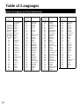
Table of Languages............................................................................................. 60
Additional Operation
Recording Using the Connected Equipment....................................................... 61
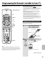
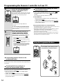
Programming the Remote Controller to Your TV ................................................. 63
Other
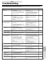
Troubleshooting................................................................................................... 65
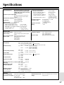
Specifications...................................................................................................... 67
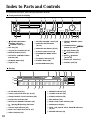
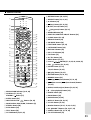
Index to Parts and Controls ............................................................................. 68
Memo .................................................................................................................. 70

6
Features
Memory Preservation
This unit does not require memory preservation batteries.
A built-in memory power backup system preserves the
contents of memory during power failures and even when
the POWER switch is set to OFF.
The POWER switch must be set to ON in order to charge
the backups system. The memory preservation period
after the unit has been turned off varies depending on
climate and placement of the unit. On average, memory
contents are protected over a period of a few weeks after
the time the unit has been turned off. This period is
shorter when the unit is exposed to a very humid climate.
Getting Started
* Manufactured under license from Digital Theater
Systems, Inc. US Pat. No.5,451,942 and other worldwide
patents issues and pending, “DTS” and “DTS Digital
Surround” are trademarks of Digital Theater Systems, Inc.
©1996 Digital Theater Systems, Inc. All Rights reserved.
** Manufactured under license from Dolby Laboratories.
“Dolby”, “Pro Logic” and the double-D symbol are
trademarks of Dolby Laboratories. Confidential
Unpublished Works. ©1992-1997 Dolby Laboratories.
All rights reserved.
*** “Theater-Dimensional” and are trademarks of
Onkyo Corporation.
Receiver Features
5 × 30 W/Ch into 6 ohms
96 kHz/24-Bit DAC System
DTS* & Dolby** Digital Decoders
Acoustic Control
2 Digital Inputs/1 Output
Subwoofer Preout
4 Audio Inputs/2 Outputs
2 S-Video Inputs/2 Outputs
Multichannel Theater-Dimensional***
Easy-Set Speaker Configuration
30 FM/AM Random Presets
Full-Function Learning Remote
DVD/CD Player Features
DTS, Dolby Digital, and PCM Compatible
Component-Video Output
27 MHz/10-Bit Video DAC
Plays DVDs, CDs, CD-Rs and Video CDs
Enhanced Black-Level Control
High-Resolution Onscreen Display
3-Mode Zoom Function
Program Memory Playback
Auto Last Play
Dual-Wavelength Optical Pickup
Sand-Blasted Aluminum Front Panel

7
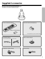
Supplied Accessories
Make sure your box contains everything listed below.
If any pieces are missing, contact your nearest Onkyo dealer.
The number of accessories is indicated in brackets.
S video cable [1]
FM antenna (aerial) [1] AM loop antenna (aerial) [1]
Batteries (size AA/R6/UM3) [2]
Remote controller (RC-437M) [1]
Audio/video connection cable [1]
FM outdoor antenna (aerial) adapter [1]*
(USA and Canadian models) (Other models)
* Not supplied for USA and Canadian models

8
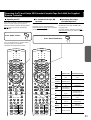
Preparing the Remote Controller
Inserting the Batteries
1 Detach the battery cover.
2 Insert the two size AA/R6/UM3 batteries.
Be sure to match the + and – ends of the batteries with
the diagram inside the battery compartment.
3 Attach the battery cover.
Using the Remote Controller
Switching the remote controller function
modes
Some buttons on the remote controller have two or
more functions. To set the functionality of these buttons,
press one of the four MODE (AUDIO, DVD, TA/MD, TV)
buttons in advance.
The function mode remains the same until another
MODE button is pressed.
(Details about the functions and the related function
modes are explained in each section.)
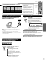
Notes
• When the batteries are getting weak, the SEND/
LEARN indicator on the remote controller starts
flashing. In this case, replace the batteries with
new ones.
For the other functions of this indicator, see
“Pointing the remote controller in the right
direction” on the right, and page 63.
• Do not mix new batteries with old batteries or
different kinds of batteries.
• To avoid corrosion, remove the batteries if the
remote controller is not to be used for a long time.
• Remove dead batteries immediately to avoid damage from
corrosion. If the remote controller does not operate smoothly,
replace both batteries at the same time.
• The life of the supplied batteries is about six months but this varies
depending on usage.
Pointing the remote controller in the right
direction
Point the remote controller toward the remote control
sensor.
Notes
• Place the unit away from strong light such as direct sunlight or
inverted fluorescent light which can prevent proper operation of the
remote controller.
• Using another remote controller of the same type in the same room
or using the unit near equipment which uses infrared rays may
cause operational interference.
• Do not put any object (such as a book) on the remote controller. The
buttons of the remote controller may be pressed by mistake and
drain the batteries.
• Make sure the audio rack doors do not have colored glass. Placing
the unit behind such doors may prevent proper remote controller
operation.
• If there is any obstacle between the remote controller and the
remote control sensor, the remote controller will not operate.
Press MODE AUDIO first before operating the speaker
setting and sound related operations.
Press MODE TA/MD first before operating the Onkyo
MD recorder or z-connected cassette tape deck (see
pages 16 and 31).
Press MODE TV first before operating your TV.
To operate the TV with the supplied remote controller,
you need to let the remote controller learn the TV
remote control signals (see pages 31 and 63).
12
3
SEND/LEARN
indicator
This indicator is lit
while any button
on the remote
controller is
pressed.
30˚
30˚
About 5 m (16 feet)
Remote control sensor
SEND/LEARN
indicator
I
N
P
U
T
S
E
L
E
C
T
O
R
M
O
D
E
A
U
D
I
O
D
V
D
T
V
T
A
/
M
D
L
I
S
T
E
N
I
N
G
M
O
D
E
A
.
C
T
R
L
T
–
D
S
T
E
R
E
O
S
U
R
R
T
I
T
L
E
M
E
N
U
S
E
T
U
P
T
V
/
V
C
R
R
E
T
U
R
N
CH
TUN
VOLENTER
REPEAT MUTING
A – B
REC
DIMMER
OPEN/CLOSE
RANDOM SLOW
SUBTITLE – ON / OFF
ANGLE ZOOM
S
T
N
B
Y
O
N
S
L
E
E
P
M
O
D
E
A
U
D
I
O
D
V
D
T
V
T
A
/
M
D
M
O
D
E
A
U
D
I
O
D
V
D
T
V
T
A
/
M
D
MODE buttons
Press MODE DVD first before operating
the built-in DVD player.
M
O
D
E
A
U
D
I
O
D
V
D
T
V
T
A
/
M
D
I
N
P
U
T
S
E
L
E
C
T
O
R
M
O
D
E
A
U
D
I
O
D
V
D
T
V
T
A
/
M
D
L
I
S
T
E
N
I
N
G
M
O
D
E
A
.
C
T
R
L
T
–
D
S
T
E
R
E
O
S
U
R
R
T
I
T
L
E
M
E
N
U
S
T
N
B
Y
O
N
S
L
E
E
P
S
E
N
D
L
E
A
R
N
I
N
P
U
T
S
E
L
E
C
T
O
R
M
O
D
E
D
V
D
T
A
/
M
D
S
T
N
B
Y
O
N
S
L
E
E
P
S
E
N
D
L
E
A
R
N

9
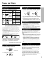
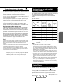
Playback side
This section shows you how to handle, clean, and store discs.
Cleaning Discs
• Fingerprints and dust on the disc cause picture and sound
deterioration. Wipe the disc from the center outwards with a
soft cloth. Always keep the disc clean.
• If you cannot wipe off the dust with a soft cloth, wipe the disc
lightly with a slightly moistened soft cloth and finish with a
dry cloth.
• Do not use any type of solvent such as thinner, benzine,
commercially available cleaners or antistatic spray for vinyl
LPs. It may damage the disc.
Storing Discs
• Do not store discs in a place subject to direct sunlight or
near heat sources.
• Do not store discs in places subject to moisture and dust
such as a bathroom or near a humidifier.
• Store discs vertically in a case. Stacking or placing objects
on discs outside of their case may cause warping.
Notes on Discs
Handling Discs
• Do not touch the playback side of the disc.
• Do not attach paper or tape to discs.
Disc mark
Disc
size
DVD
videos
Playable Discs
This DVD Receiver can playback the following discs.
• You cannot playback discs other than those listed above.
• You cannot play discs such as CD-RW, CD-ROM, DVD-
RAM, DVD-RW, etc., even if the marks in the above table
are labeled on those discs.
• This DVD Receiver uses the PAL*/NTSC color system, and
cannot playback DVD videos recorded in any other color
system (SECAM, etc.).
• Avoid using heart-shaped or octagonal discs. Playing
irregularly shaped discs may damage the internal
mechanism of the DVD Receiver.
• Do not use discs that have residue from adhesive tape,
rental discs that have peeling labels, or discs that have
custom labels or stickers. Otherwise, you may not be able
to eject the discs or the DVD Receiver may become
inoperative.
Notes on Copyright
It is forbidden by law to copy, broadcast, show, broadcast on
cable, play in public, and rent copyrighted material without
permission.
DVD videos are copy protected, and any recordings made
from these discs will be distorted.
This product incorporates copyright protection technology that
is protected by method claims of certain U.S. patents and
other intellectual property rights owned by Macrovision
Corporation and other rights owners. Use of this copyright
protection technology must be authorized by Macrovision
Corporation, and is intended for home and other limited
viewing uses only unless otherwise authorized by Macrovision
Corporation. Reverse engineering or disassembly is
prohibited.
About VIDEO CDs
This DVD Receiver supports VIDEO CDs equipped with the
PBC (Version 2.0) function. (PBC is the abbreviation for
Playback Control.)
You can enjoy two playback variations depending on the type
of disc.
• VIDEO CD not equipped with PBC function (Version 1.1)
Sound and movies can be played on this DVD Receiver in
the same way as an audio CD.
• VIDEO CD equipped with PBC function (Version 2.0)
In addition to operation of a VIDEO CD not equipped with
the PBC function, you can enjoy playback with interactive
software and search function using the menu displayed on
the TV screen (Menu Playback). Some of the functions
described in this Instruction Manual may not work with some
discs.
Contents
Audio
+
Video
(moving
pictures)
VIDEO
CDs
Audio
CDs*
Audio
Audio +
Video
(moving
pictures)
Approx. 4 hours
(single sided disc)
Approx. 8 hours
(double sided disc)
Approx. 80 minutes
(single sided disc)
Approx. 160 minutes
(double sided disc)
Approx. 74 minutes
Maximum
playback time
Approx. 74 minutes
Approx. 20 minutes
Approx. 20 minutes
8 cm (CD
single)
12 cm
8 cm
12 cm
8 cm
12 cm
* Finalized CD-Rs are also playable.
Such CD-Rs that TOC (Table of Contents) information (such
as truck numbers) are recorded on to the PMA –– a special
area in the disc is described as finalized CD-Rs.
* Not applicable for USA and Canadian models

10
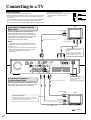
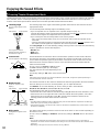
Connecting to a TV
Before connecting
• Refer also to the instruction manual of the TV.
• When you connect the DVD Receiver to the TV, be sure to turn off the
power and unplug both the units from the mains before making any
connections.
• Connect the DVD Receiver to the TV directly. If you connect the DVD
Receiver to a VCR, TV/VCR combination, or video selector, the
playback picture may be distorted as DVD videos are copy protected.
(White)
L (White)
R (Red)
To audio outputs
(Red)
(White)
TV
• Connect the plugs securely.
• Note that one audio/video connection cable
and one S video connection cable are
supplied.
Incomplete
Insert completely
TV
: Signal flow
(Red)
Stereo audio connection cable
Video connection cable
L (White)
To audio outputs
R (Red)
(Yellow)
To video input
To S video input
REMOTE
CONTROL
OUT
OUT
VIDEO 11 – VIDEO – 2
ININOUT IN
IN OUT
(REC)
IN
(PLAY)
IN
IN
VIDEO 2
VIDEO
1
VIDEO
2
TAPE/MD
SUB
WOOFER
PRE OUT
CENTER
SPEAKER
SURROUND
SPEAKERS
S VIDEO
AUDIO
R
L
IN
TV/LINE
MON
OUT
MON
OUT
L
VIDEO
AUDIO
R
R
L
R
BA
L
FRONT SPEAKERS
FM 75
ANTENNA
AM
DIGITAL OUTPUT
VIDEO 1
(OPT)(OPT) (COAX)
VIDEO 2
DIGITAL INPUT
YP
B
P
R
COMPONENT VIDEO OUTPUT
S video connection cable
Both the S video and video connections are necessary,
otherwise the picture from equipment to be connected on
the next page may not be output to the TV.
Connecting to a TV With Component
Video Inputs
If the TV or monitor has component video
inputs, make this connection. Connecting to
these inputs allows you to enjoy higher quality
picture playback compared to the connections
explained in “Connecting to a TV Without
Component Video Inputs” below.
Notes
• Actual labels for component video inputs may vary
depending on the TV manufacturer (ex. Y/CB/CR, Y/
B-Y/R-Y, etc.).
• In some TVs, the color levels of the playback picture
may be reduced slightly or the tint may change. In
such a case, adjust the TV for optimum
performance.
Connecting to a TV Without
Component Video Inputs
If the TV or monitor has an S video input, make
the S video connection. The S video connection
will provide higher quality picture playback.
Y
To component
video inputs
PB PR
Stereo audio connection cable
Component video connection
cable
Only pictures from a DVD video or
VIDEO CD played with the DVD
Receiver will be output to the TV.
(Yellow)
DO NOT connect the
power cord (mains lead)
at this time.

11
REMOTE
CONTROL
CENTER
SPEAKER
SURROUND
SPEAKERS
R
L
OUT
OUT
VIDEO 11 – VIDEO – 2
ININOUT IN
IN OUT
(REC)
IN
(PLAY)
IN
IN
VIDEO 2
VIDEO
1
VIDEO
2
TAPE/MD
MON
OUT
L
R
S VIDEO
VIDEO
AUDIO AUDIO
IN
TV/LINE
MON
OUT
SUB
WOOFER
PRE OUT
OUT
OUT INOUT
IN
VIDEO
1
IN
OUT
(REC)
IN
(PLAY)
IN
IN
IN
VIDEO 2
VIDEO
2
TAPE/MD TV/LINE
MON
OUT
MON
OUT
SUB
WOOFER
PRE OUT
L
R
S VIDEO
VIDEO
AUDIO AUDIO
OUT
OUT INOUT
VIDEO
1
IN
IN
IN
IN
IN
VIDEO 2
VIDEO
2
TV/LINE
MON
OUT
MON
OUT
SUB
WOOFER
PRE OUT
L
R
S VIDEO
VIDEO
AUDIO AUDIO
VIDEO 11 – VIDEO – 2
IN
OUT
OUT
INOUT
VIDEO
1
IN
OUT
(REC)
IN
(PLAY)
IN
IN
IN
VIDEO
2
TAPE/MD TV/LINE
MON
OUT
MON
OUT
SUB
WOOFER
PRE OUT
L
R
S VIDEO
VIDEO
AUDIO AUDIO
VIDEO 1
IN
VIDEO 2
OUT
(REC)
IN
(PLAY)
TAPE/MD
R
L
R
BA
L
FRONT SPEAKERS
1 – VIDEO – 2
DIGITAL OUTPUT
VIDEO 1
(OPT)(OPT) (COAX)
VIDEO 2
DIGITAL OUTPUT
VIDEO 1
(OPT)(OPT) (COAX)
VIDEO 2
VIDEO 11 – VIDEO – 2
IN IN
FM 75
ANTENNA
AM
DIGITAL OUTPUT
VIDEO 1
(OPT)(OPT) (COAX)
VIDEO 2
DIGITAL INPUT
DIGITAL INPUT DIGITAL INPUT
VIDEO 1
(OPT) (COAX)
VIDEO 2
DIGITAL INPUT
(OPT)
DIGITAL OUTPUT
YP
B
P
R
COMPONENT VIDEO OUTPUT
Connecting to Audio/Video Equipment
Before connecting
• Refer also to the instruction manual of each component to be
connected.
• When you connect the DVD Receiver to audio/video equipment, be
sure to turn off the power and unplug all the units from the mains before
making any connections.
• About the DIGITAL INPUT (OPT) and DIGITAL
OUTPUT (OPT) connectors
Remove the protective caps before making connections.
When not in use, be sure to replace them.
• About the VIDEO 1 and VIDEO 2 jacks/connectors
The video input/output connections are also necessary even if you
make the S video input/output connections.
• Connect the plugs securely.
• Note that one audio/video connection cable
and one S video connection cable are
supplied (if not used in the connection on
the opposite page).
Incomplete
Insert completely
L (White)
R (Red)
(Yellow)
(Yellow)
L (White)
R (Red)
(White)
(Yellow)
(Red)
(White)
(Yellow)
(Red)
: Signal flow
VCR, DVD Recorder, etc.
MD Recorder, DAT,
Cassette Tape Deck,
CD Recorder, etc.
Set Top Box, LD Player,
Video Cassette Player, etc.
L (White)
R (Red)
(Yellow)
S video
connection
cable
Audio/video
connection
cable
S video connection cable
Audio/video
connection
cable
To S video
output
To S video
input
Stereo audio connection cable
R (Red)
L (White)
L (White)
R (Red)
(White)
(Red)
(Red)
(White)
To digital coaxial
audio output
To digital optical
audio output
Coaxial
connection
cable
Optical fiber cable
(White)
(Yellow)
(Red)
To S video
output
To digital optical
audio input
To audio
inputs
To video
input
To video
output
To audio
outputs
To video output
To audio
outputs
To audio
inputs (REC)
To audio outputs (PLAY)
This connection is only for
equipment with a digital
optical/coaxial audio
output.
Digital recording is not
always possible; therefore,
also connect to the analog
audio jacks (see page 61
for recording sound).
Optical fiber cable
This connection is only for equipment with a digital optical audio input.
Digital recording is not always possible; therefore, also connect to the analog audio jacks
(see page 61 for recording sound).
To VIDEO 1
To VIDEO 2
To TAPE/MD
DO NOT connect the
power cord (mains lead)
at this time.

1212
Positioning Speakers
Two speaker systems (SPEAKERS A and SPEAKERS B) can be connected to the DVD Receiver.
The SPEAKERS A system is to be placed in the main room, and the SPEAKERS B system is to be placed in a second room.
The configuration of the SPEAKERS A system
The SPEAKERS A system consists of the front left, center, and right speakers, surround left and right speakers, and subwoofer.
You can reproduce the sounds such as Dolby surround and DTS surround.
The configuration of the SPEAKERS B system
The SPEAKERS B system consists of the front left and right speakers.
You can reproduce only monaural and stereo sounds.
Standard speaker placement of the SPEAKERS A system
Speaker placement plays an important role in the reproduction of Surround sound. The placement of the speakers varies depending
on the size of the room and the wall coverings used in the room. The illustration below shows an example of a layout for standard
speaker placement. Refer to this example when you position the speakers in order to experience the best of Surround sound.
For ideal Surround effects, all speakers should be installed.
If a center speaker or subwoofer is not connected, the sound from the unused channel is properly distributed to the connected
speakers in order to reproduce the best Surround sound possible.
Front
The center speaker reproduces a richer sound image by enhancing the
perception of the sound's source and movement.
The left, right, and center speakers should face the seated listener and be
placed at ear level.
Surround
The surround speakers reproduce the feel of a moving sound while creating
the sensation of being in the middle of the action.
Place the left and right surround speakers 1 meter (3 feet) above the
listener's ear level and facing toward the sides of the room, making sure that
the listener is within the speakers' dispersion angle.
Subwoofer
Install a subwoofer with a built-in power amplifier for powerful bass sounds.
The placement of the subwoofer does not affect the final quality of the sound
image much, therefore, you can install it wherever it is convenient.
Refer to the speakers’ instruction manuals for details.
TV/Screen
Front
Center
Speaker
Front
right
Speaker
Front
left
Speaker
Sub-
woofer
Surround
left
Speaker
Surround
right
Speaker

1313
REMOTE
CONTROL
OUT
OUT
VIDEO 11 – VIDEO – 2
ININOUT IN
IN OUT
(REC)
IN
(PLAY)
IN
IN
IN
VIDEO 2
VIDEO
1
VIDEO
2
TAPE/MD TV/LINE
MON
OUT
MON
OUT
L
R
S VIDEO
VIDEO
AUDIO
SUB
WOOFER
PRE OUT
CENTER
SPEAKER
SURROUND
SPEAKERS
AUDIO
R
L
CENTER
SPEAKER
SURROUND
SPEAKERS
R
L
R
L
R
BA
L
FRONT SPEAKERS
R
L
B
FRONT SPEAKERS
R
A
L
FRONT SPEAKERS
R
A
L
R
L
B
CENTER
SPEAKER
SURROUND
SPEAKERS
R
L
FM 75
ANTENNA
DIGITAL OUTPUT
VIDEO 1
(OPT)(OPT) (COAX)
VIDEO 2
DIGITAL INPUT
AM
YPB PR
COMPONENT VIDEO OUTPUT
+–+–
+–+–
+–
+– +–
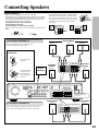
Connecting Speakers
Before connecting
• Refer also to the instruction manuals of the speakers.
• This DVD Receiver is designed to reproduce optimum sound quality
when speakers with the impedances specified below are connected.
Please check the following information and choose speakers with
appropriate impedances for the connections.
Front speakers: 6 ohms min. per speaker
Center speaker: 6 ohms min.
Surround Speakers : 6 ohms min. per speaker
• Strip 10 mm from the end of each cord, then twist the exposed wires
tightly.
• To prevent damage to circuits, never short-circuit
the positive (+) and negative (–) speaker wires.
• Do not connect the speaker cable to the L and R
connectors at the same time and do not connect
more than one speaker to the same speaker
connectors.
Front speakers
Right ch. Left ch.
Surround
speaker
Right ch.
10
mm
Active
subwoofer
Center ch.
Surround
speaker
Left ch.
Connecting to SPEAKERS A
The main speaker system is SPEAKERS A.
Follow the illustration on the right.
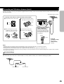
How to connect to the speaker
connectors
Press and hold
the lever.
Insert the stripped
end of the cord.
By releasing the
lever, the lever is
replaced.
Front speaker
Right ch.
Front speaker
Left ch.
Connecting to SPEAKERS B
To place the additional speaker system for the second
room, make the SPEAKERS B connection on the right.
NO!
DO NOT connect the
power cord (mains lead)
at this time.
NO!
NO!
+
–
LR
+
–
LR

1414
REMOTE
CONTROL
OUT
OUT
VIDEO 11 – VIDEO – 2
ININOUT IN
IN OUT
(REC)
IN
(PLAY)
IN
IN
IN
VIDEO 2
VIDEO
1
VIDEO
2
TAPE/MD TV/LINE
MON
OUT
MON
OUT
L
R
S VIDEO
VIDEO
AUDIO
SUB
WOOFER
PRE OUT
CENTER
SPEAKER
SURROUND
SPEAKERS
R
L
R
BA
L
FRONT SPEAKERS
AUDIO
R
L
AM
FM 75
ANTENNA
DIGITAL OUTPUT
VIDEO 1
(OPT)(OPT) (COAX)
VIDEO 2
DIGITAL INPUT
YP
B
P
R
COMPONENT VIDEO OUTPUT
Connecting an AM Outdoor Antenna (Aerial)
Outdoor antenna (aerial)
AM indoor antenna (aerial)
Making Antenna (Aerial) Connections
Connecting the Supplied FM and AM Indoor Antennas (Aerials)
Press up and
hold the lever.
Insert the end of
the cord.
Release the lever to
secure the connection.
Adjusting the position of the FM indoor antenna (aerial)
While listening to an FM program (see page 28), extend the antenna (aerial) and
move it in various directions until the clearest signal is received, then secure the
antenna (aerial) with push pins in the position with the least distortion.
Adjusting the position of the AM indoor antenna (aerial)
While listening to an AM program (see page 28), set the antenna (aerial) in the
direction and position where you receive the clearest sound.
Put it as far away as possible from the unit, TVs, speaker cables, and power cords
(mains leads).
Note
Insert one end of the AM antenna
(aerial) cord to either of the AM antenna
(aerial) connectors and the other end to
the other connector. There is no
difference between one end of the AM
antenna (aerial) cord and the other end,
unlike the speaker cords which have
positive and negative poles.
FM 75
AM
ANTENNA
AM indoor antenna (aerial)
Insert into the hole.
FM indoor antenna (aerial)
DO NOT connect the
power cord (mains lead)
at this time.
An outdoor antenna (aerial) will be more effective if it is stretched
horizontally above a window or outside.
Leave the supplied AM indoor antenna (aerial) connected.
Note
To avoid the risk of lightning and electrical shock, grounding is necessary.
Follow item 14 of the "Important Safeguards" on page 2 when you install
an outdoor antenna (aerial).
(USA and
Canadian
models)
(Other
models)
FM 75
ANTENNA
AM

1515
FM 75
ANTENNA
AM
Connecting an FM Outdoor Antenna (Aerial)
If the FM reception is not very clear with the supplied antenna (aerial), connect an FM outdoor antenna (aerial) instead of the indoor
FM antenna (aerial).
Notes
• Install the antenna (aerial) well away from tall buildings and in an area where FM stations can directly be received.
• Keep the antenna (aerial) away from noise sources (neon signs, busy roads, etc.).
• It is dangerous to put the antenna (aerial) close to power lines. Keep it well away from power lines, transformers, etc.
• To avoid the risk of lightning and electrical shock, grounding is necessary. Follow item 14 of the "Important Safeguards" on page 2 when you install
the outdoor antenna (aerial).
Directional Iinkage
Do not use the same antenna (aerial) for both FM and TV (or VCR) reception since the FM and TV (or VCR) signals can interfere
with each other. If you must use a common FM/TV (or VCR) antenna (aerial), use a directional linkage type splitter.
Directional linkage
type splitter
To DVD Receiver To TV (or VCR)
FM outdoor antenna (aerial)
Connecting 300 ohm ribbon
wire to a 75/300 ohm
antenna (aerial) adapter*
Loosen the screws and wrap
the wire around these screws.
Then tighten the screws with
a screwdriver.
Tighten
Loosen
Connecting coaxial cable to a 75/300 ohm antenna (aerial) adapter*
3 Remove the transformer wire A
from slit B and insert it into slit C.
4 Insert the end of the cable.
5 Clamp it in place with pliers.
6 Reinstall the cover.
4
5
1 Strip the end of the coaxial cable.
2 With your fingernail or a small
screwdriver, press the stoppers
outward and remove the cover.
Slit B
Slit C
Wire A
15 mm
3
mm
6
mm
6
mm
5
/8 in.
1
/8
in.
1
/4
in.
1
/4
in.
* (USA and
Canadian models)
Not supplied
(Other models)
Supplied

1616
CENTER
SPEAKER
SURROUND
SPEAKERS
R
L
R
L
R
BA
L
FRONT SPEAKERS
OUT
OUT
VIDEO 11 – VIDEO – 2
ININOUT IN
IN OUT
(REC)
IN
(PLAY)
IN
IN
IN
VIDEO 2
VIDEO
1
VIDEO
2
TAPE/MD TV/LINE
MON
OUT
MON
OUT
SUB
WOOFER
PRE OUT
L
R
S VIDEO
VIDEO
AUDIO AUDIO
REMOTE
CONTROL
FM 75
ANTENNA
AM
DIGITAL OUTPUT
VIDEO 1
(OPT)(OPT) (COAX)
VIDEO 2
DIGITAL INPUT
YP
B
P
R
COMPONENT VIDEO OUTPUT
z Connection for the Onkyo Cassette Tape Deck
Onkyo cassette tape deck
Notes
• Connect the plugs securely.
• Be sure to connect to the z connectors using the z cable.
• The connections on page 11 are needed even if z connection is
made.
• Do not connect the DVD Receiver’s z connector to any component
other than an Onkyo product. It may cause malfunction.
Incomplete
Insert completely
DO NOT connect the
power cord (mains lead)
at this time.
The supplied remote controller has the following three extended functions in addition to operating the DVD Receiver:
• First, operating the TV (see page 31),
• Second, operating the Onkyo MD recorder (no z connection is needed) (see page 31), and
• Third, operating the z connected Onkyo cassette tape deck through the DVD Receiver (see page 31).
To use the third function, you need to make the z connection between the cassette tape deck and the DVD Receiver. The z
cable to make the z connection is supplied with the cassette tape deck.
If you start playing back the cassette tape deck after making the z connection, the DVD Receiver automatically changes its input
source to the cassette tape deck –– Direct Change function.
z cable

1717
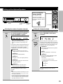
FIRST SETUP
TV Shape
4:3LB
Thank you for your purchase of Our DVD-Video Player.
Please make a selection
for On-Screen Language and your TV shape and
press ENTER button on your remote control.
On-Screen Language
ENG
FM MODE
STANDBY/ON
STANDBY
POWER
PHONES
OFF
ON
TUNING/PRESET
SURROUND STEREO
T – D
DISPLAY
DVD / CD
PRESET
MEMORY
SUBWOOFER
MODE
SPEAKER
SETUP
SPEAKER
A / B
ACOUSTIC
CONTROL
INPUT
MASTER VOLUME
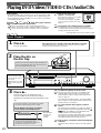
Connecting the Power/Turning on the DVD
Receiver
Before connecting
• Make sure that all the connections from pages 10 to 16 are complete (the connection to the TV is required).
• Turning on the DVD Receiver may cause a momentary power surge, which might interfere with other electrical equipment such as computers. If
this happens, use a wall outlet on a different circuit.
2 Press the POWER switch to
switch on the main power.
The DVD Receiver enters standby mode.
The STANDBY indicator lights up.
Notes
• To switch off the main power, press the POWER switch again.
• The buttons on the remote controller don’t operate if the POWER
switch is set to OFF.
1 Connect the power cord (mains lead)
to a wall outlet (the mains).
I
N
P
U
T
S
E
L
E
C
T
O
R
M
O
D
E
A
U
D
I
O
D
V
D
T
V
T
A
/
M
D
L
I
S
T
E
N
I
N
G
M
O
D
E
A
.
C
T
R
L
T
–
D
S
T
E
R
E
O
S
U
R
R
T
I
T
L
E
M
E
N
U
S
E
T
U
P
T
V
/
V
C
R
R
E
T
U
R
N
CH
TUN
VOLENTER
REPEAT MUTING
A – B
REC
DIMMER
OPEN/CLOSE
RANDOM SLOW
SUBTITLE – ON / OFF
ANGLE ZOOM
MEMORY CLEAR AUDIO DISPLAY
--
/
---
SW MODE
LATE NIGHT DISTANCE
CH SEL
T– D SETUP
UP/ DOWN
TEST TONE
SP A
SP B
123
456
789
+
10 0
SEARCH
S
T
N
B
Y
O
N
S
L
E
E
P
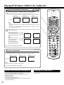
3 Press STANDBY/ON on the DVD
Receiver or ON on the remote controller.
The DVD Receiver turns on.
The light and display on the DVD Receiver’s
front panel light. At the same time, the
STANDBY indicator goes off.
The first time you turn on the DVD Receiver, the FIRST
SETUP screen appears. In the FIRST SETUP screen, select
the On-Screen Language and TV Shape according to the
aspect ratio of the TV screen (see pages 54 and 55).
1 Press
/ to select “On-Screen Language,” then press
ENTER.
2 Select a language with / , then press ENTER.
3 Press
to select “TV Shape,” then press ENTER.
4 Press
/ to select the aspect ratio of the TV screen,
then press ENTER.
5 Finally press SETUP.
All of your selections are set and the FIRST SETUP
screen disappears.
Notes
• To turn off the DVD Receiver, press STANDBY/ON on the DVD
Receiver, or STNBY on the remote controller. The DVD Receiver
enters standby mode. Be sure to set the volume to minimum before
turning off the DVD Receiver.
• You can change the above settings later with “Customizing the
Function Settings” on page 52.
↔
Before operating the cursor
Press MODE DVD or MODE AUDIO.
ENTER
ENTER
S
E
T
U
P
T
V
/
V
C
R
FM MODE
STANDBY/ON
STANDBY
POWER
PHONES
OFF
ON
TUNING/PRESET
SURROUND STEREO
T – D
DISPLAY
DVD / CD
PRESET
MEMORY
SUBWOOFER
MODE
SPEAKER
SETUP
SPEAKER
A / B
ACOUSTIC
CONTROL
INPUT
MASTER VOLUME
STANDBY

18
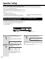
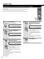
Speaker Setup
1
2
3
Unit only
Press SPEAKER SETUP.
Smart Configuration is complete.
Press SPEAKER SETUP.
“SmartConfig” appears in the display.
Note
If any display appears other than “SmartConfig,”
press the button repeatedly until “SmartConfig”
appears.
Press SPEAKER A/B to select
“Spk Set A.”
Note
“Spk Set B” also appears by pressing the
button repeatedly, though, this setting is
reserved for future applications. Therefore, be
sure to select “Spk Set A.”
Tip
For precise setting, carry out “Setting the Distance From the Listening
Position to Each Speaker” on page 20.
Setting up the Optional Speaker System –– Smart Configuration Setting
(Only for USA and Canadian models)
Use the Smart Configuration setting to set up the optional speaker system.
The optional speaker system is composed of the following speakers:
• D-30 (front left and right, and surround left and right speakers)
• D-30C (front center speaker)
• SKW-30 (subwoofer)
FM MODE
STANDBY/ON
STANDBY
POWER
PHONES
OFF
ON
TUNING/PRESET
SURROUND STEREO
T – D
DISPLAY
DVD / CD
PRESET
MEMORY
SUBWOOFER
MODE
SPEAKER
SETUP
SPEAKER
A / B
ACOUSTIC
CONTROL
INPUT
MASTER VOLUME
Display SPEAKER SETUP
You need to set up the speaker configuration for the speaker system connected to the SPEAKERS A connectors (see page 13.)
(There is no speaker configuration setup for the SPEAKERS B system.)
If you purchased the optional speaker system with the DR-S2.0 DVD Receiver, follow the steps in “Setting up the Optional Speaker
System –– Smart Configuration Setting” below.
Follow the steps in “Setting up Non-Optional Speakers” on the next page if:
• Your DVD Receiver is not a USA nor Canadian model, or
• Your speakers are not the optional speaker system of the DVD Receiver.
Notes
• Speaker setup cannot be done if;
– Headphones are connected (see page 33), or
– The SPEAKERS B system is On (see page 32).
• It is not necessary to set the parameters again once you have completed the
setup (with one exception*) unless you change the speaker configuration.
SPEAKER
A / B
SPEAKER
SETUP
SPEAKER
SETUP
SPEAKER A/B
* See “To Listen to a High-Frequency/High-Quantization
Format Source in its Original Sound Quality – 96k Sound”
on page 48.

19
→
FM MODE
STANDBY/ON
STANDBY
POWER
PHONES
OFF
ON
TUNING/PRESET
SURROUND STEREO
T – D
DISPLAY
DVD / CD
PRESET
MEMORY
SUBWOOFER
MODE
SPEAKER
SETUP
SPEAKER
A / B
ACOUSTIC
CONTROL
INPUT
MASTER VOLUME
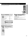
Setting up Non-Optional Speakers
SPEAKER
SETUP
Display SPEAKER
SETUP
I
N
P
U
T
S
E
L
E
C
T
O
R
M
O
D
E
A
U
D
I
O
D
V
D
T
V
T
A
/
M
D
L
I
S
T
E
N
I
N
G
M
O
D
E
A
.
C
T
R
L
T
–
D
S
T
E
R
E
O
S
U
R
R
T
I
T
L
E
M
E
N
U
S
E
T
U
P
T
V
/
V
C
R
R
E
T
U
R
N
CH
TUN
VOLENTER
REPEAT MUTING
A – B
REC
DIMMER
OPEN/CLOSE
RANDOM SLOW
SUBTITLE – ON / OFF
ANGLE ZOOM
MEMORY CLEAR AUDIO DISPLAY
--
/
---
SW MODE
LATE NIGHT DISTANCE
CH SEL
T– D SETUP
UP/ DOWN
TEST TONE
SP A
SP B
123
456
789
+
10 0
SEARCH
S
T
N
B
Y
O
N
S
L
E
E
P
A
U
D
I
O
Unit
Remote controller
SUBWOOFER
MODE
SW MODE
1
Before operating the
remote controller
Press MODE AUDIO.
The remote controller
remains in the AUDIO mode,
until another MODE button is
pressed.
→
Setting the Subwoofer Mode
Press SUBWOOFER MODE on the
unit or SW MODE on the remote
controller.
With the first press of the button, you can
check the present setting. Then each press
of the button changes the subwoofer mode
as follows (a tip on how to select the right
subwoofer mode is in parentheses):
SW Mode 2*
(When large–wideband–front speakers
are connected)
↓
SW Off
(When no subwoofer is connected)
↓
SW Mode 1
(When small–with limited bass signal
handling–front speakers are
connected)
The normal display resumes in three
seconds.
SUBWOOFER
MODE
SW MODE
→
Unit only
* (For USA and Canadian models)
The display appears in the following order:
SW Mode 1
↓
SW Mode 2
↓
SW Off
Selecting the number of speaker channels
Press SPEAKER SETUP repeatedly
to select the number of channels
for the SPEAKERS A system.
(USA and Canadian models)
Alghough “SmartConfig” may appear in the
display, do not select “SmartConfig” in this
step.
Pressing the button repeatedly within three
seconds changes the number of channels
as follows (the corresponding speaker
configuration is described in parentheses):
SmartConfig
Appears if your DVD Receiver is the USA or
Canadian model. Do not select this in this step.
↓
Speaker 2
ch
(Front left and right speakers)
↓
Speaker 3
ch
(Front left, center, and right speakers)
↓
Speaker 4
ch
(Front left and right, plus surround left
and right speakers)
↓
Speaker 5
ch
(Front left, center, and right, plus
surround left and right speakers)
The normal display resumes in three
seconds.
Notes
• The listening mode will automatically be set to
“Stereo” (see page 38) once you set or reset
the number of channels.
• To check the present setting while the normal
display is displayed, press SPEAKER SETUP
once. To change the setting, press the button
repeatedly within three seconds.

20
Speaker Setup
1
2
Setting the Distance From the Listening Position to Each Speaker
Before starting the procedure below, measure the distances from each speaker to the
listening position.
For pair speakers such as front left and right speakers, the distance from the listening
position to one speaker should be the same as the distance to the other.
In the procedure below, select the values which approximate the actual distances.
1,3-5
I
N
P
U
T
S
E
L
E
C
T
O
R
M
O
D
E
A
U
D
I
O
D
V
D
T
V
T
A
/
M
D
L
I
S
T
E
N
I
N
G
M
O
D
E
A
.
C
T
R
L
T
–
D
S
T
E
R
E
O
S
U
R
R
T
I
T
L
E
M
E
N
U
S
E
T
U
P
T
V
/
V
C
R
R
E
T
U
R
N
CH
TUN
VOLENTER
REPEAT MUTING
A – B
REC
DIMMER
OPEN/CLOSE
RANDOM SLOW
SUBTITLE – ON / OFF
ANGLE ZOOM
MEMORY CLEAR AUDIO DISPLAY
--
/
---
SW MODE
LATE NIGHT DISTANCE
CH SEL
T– D SETUP
UP/ DOWN
TEST TONE
SP A
SP B
123
456
789
+
10 0
SEARCH
S
T
N
B
Y
O
N
S
L
E
E
P
2-4
Press DISTANCE, then press UP /
DOWN repeatedly to select the
surround left and right speaker
distance.
You cannot enter the following distances:
• Distances longer than the distance set
for the front speakers.
• Distances shorter than the distance
obtained by subtracting “4.5 m (15 ft.)”
from the distance entered for the front
speakers.
Note
If you selected a speaker configuration with no
surround speakers on the previous page, this
step will be skipped.
Press DISTANCE.
The normal display resumes.
Remote controller
only
DISTANCE
5
UP/ DOWN
9
SEARCH
UP/ DOWN
9
SEARCH
DISTANCE
5
UP/ DOWN
9
SEARCH
DISTANCE
5
3
4
DISTANCE
5
5
m
m
m
m
Press DISTANCE.
The distance entry display for the front left
and right speakers appears.
Press UP /DOWN to select the
front left and right speaker
distance.
You can select a distance between 0.3 m
and 9 m (1 ft. and 30 ft.).
Press DISTANCE, then press UP /
DOWN repeatedly to select the
center speaker distance.
You cannot enter the following distances:
• Distances longer than the distance set
for the front speakers.
• Distances shorter than the distance
obtained by subtracting “1.5 m (5 ft.)”
from the distance entered for the front
speakers.
Note
If you selected a speaker configuration with no
center speaker on the previous page, this step
will be skipped.
Page is loading ...
Page is loading ...
Page is loading ...
Page is loading ...
Page is loading ...
Page is loading ...
Page is loading ...
Page is loading ...
Page is loading ...
Page is loading ...
Page is loading ...
Page is loading ...
Page is loading ...
Page is loading ...
Page is loading ...
Page is loading ...
Page is loading ...
Page is loading ...
Page is loading ...
Page is loading ...
Page is loading ...
Page is loading ...
Page is loading ...
Page is loading ...
Page is loading ...
Page is loading ...
Page is loading ...
Page is loading ...
Page is loading ...
Page is loading ...
Page is loading ...
Page is loading ...
Page is loading ...
Page is loading ...
Page is loading ...
Page is loading ...
Page is loading ...
Page is loading ...
Page is loading ...
Page is loading ...
Page is loading ...
Page is loading ...
Page is loading ...
Page is loading ...
Page is loading ...
Page is loading ...
Page is loading ...
Page is loading ...
Page is loading ...
Page is loading ...
Page is loading ...
Page is loading ...
-
 1
1
-
 2
2
-
 3
3
-
 4
4
-
 5
5
-
 6
6
-
 7
7
-
 8
8
-
 9
9
-
 10
10
-
 11
11
-
 12
12
-
 13
13
-
 14
14
-
 15
15
-
 16
16
-
 17
17
-
 18
18
-
 19
19
-
 20
20
-
 21
21
-
 22
22
-
 23
23
-
 24
24
-
 25
25
-
 26
26
-
 27
27
-
 28
28
-
 29
29
-
 30
30
-
 31
31
-
 32
32
-
 33
33
-
 34
34
-
 35
35
-
 36
36
-
 37
37
-
 38
38
-
 39
39
-
 40
40
-
 41
41
-
 42
42
-
 43
43
-
 44
44
-
 45
45
-
 46
46
-
 47
47
-
 48
48
-
 49
49
-
 50
50
-
 51
51
-
 52
52
-
 53
53
-
 54
54
-
 55
55
-
 56
56
-
 57
57
-
 58
58
-
 59
59
-
 60
60
-
 61
61
-
 62
62
-
 63
63
-
 64
64
-
 65
65
-
 66
66
-
 67
67
-
 68
68
-
 69
69
-
 70
70
-
 71
71
-
 72
72


Ask a question and I''ll find the answer in the document
Finding information in a document is now easier with AI
Related papers
Other documents
-
Akai AHC1200 User manual
-
Durabrand STS92D Owner's manual
-
Magnavox DVD815 User manual
-
Audiovox DVD Home Theater System User manual
-
Kenwood NV-301 User manual
-
Integra DTR-5.1 User manual
-
-
Panasonic sc-dk1 Owner's manual
-
Daewoo DCR-9120 User manual
-