Page is loading ...

™
WHIRLWIND QUIKPATCH PATCH BAY
Congratulations. With the purchase of the Whirlwind Quikpatch, you have made the first step in simplifying your
equipment hookup and organizing the signal flow in your system. The will allow you to spend time being creative
instead of wasting time trying to connect all your pieces of gear together. To help you get started, this sheet offers a
few tips on patchbays and a basic example of how a small recording setup might be connected through a Quikpatch.
HOOK UP HINTS
The function of a patchbay in a system is to bring the input and output connections from all of the pieces of
equipment to one central location. The top row of jacks should be connected to the outputs of the equipment and the
bottom row of jacks should be connected to the equipment inputs. This patchbay has switches built into it so that
when used properly, outputs on the top row of jacks are automatically connected to equipment inputs on the bottom
row without the use of any patch cords. This feature is known in patchbay terminology as “half-normal”. When a pair
of jacks is configured for the half-normal feature, a patch cord plugged into a bottom row jack will break the
connection to the jack above it, but a patch cord plugged into a top row jack will not. The top row patch cord simply
parallels the output and allows it to be fed into another piece of equipment.
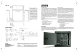
The following diagram shows a possible small studio setup with a 12-channel console. Channels 1 thru 20 make use
of the half-normal feature. Channels 21 thru 24 are connected to equipment whose outputs are over their own inputs.
In this situation no top to bottom connections or normals are required. The Quikpatch can be converted to a “non-
normal” circuit simply by removing the channel's circuit board from the metal frame and reinstalling it with the rear
jacks in front.
whirlwind
™
QUIKPATCH
PATCH BAY

™
QUIKPATCH SUMMARY
This patchbay has 48 jacks on the front for patching, and 48 jacks on the back to connect the inputs and outputs of
your gear. As shipped from the factory, the up-and-down pairs of jacks on the front are wired together in a manner
called “half-normal”. Each jack pair is built on its own rugged epoxy-glass circuit board and can be easily configured
as no-normal if desired (no signal connection between upper and lower jack). Remove the mounting nut from the
lower jack on the back of the patchbay and remove the circuit board. Rotate the circuit board 180 degrees so the
bottom rear jack becomes the upper front jack. Replace the circuit board, remembering to put the mounting nut back
on and tighten. You're done and with no soldering or cutting wires. This patchbay is fitted with 1/4-inch TRS (Tip-
Ring-Sleeve) jacks. They can be used with any standard 1/4-inch phone plug for balanced, stereo or unbalanced
operation.
SPECIFICATIONS
Dimensions: 19”(482mm) x 1.73”(44mm) x 2.68”(68mm)
Shipping Weight: 2.351bs (1.06kg)
Jack Contact Material: Solid Nickel Silver
Jack Switch Resistance: Less than .015Ohms
Model #: WPB-48S
Also available from your Whirlwind Dealer:
Whirlwind manufactures and distributes a variety of patch cords suitable for use with this and all other patch bays.
The Whirlwind Multitrack Series of multipair audio systems is ideal for interconnecting patchbays with
consoles, tape decks and rack mounted equipment.
See your Whirlwind dealer for more information.
whirlwind 99 Ling Road Rochester NY 14612 - Phone: (585) 663-8820 Fax: (585) 865-8930
www.whirlwindusa.com
/
