DRWG
1
-
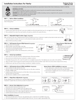
Fasten the bottom bracket (A) at the wall , make sure it is level
2
-
Put the vanity on the bracket (A) then fasten the upper bracket (B) by fixing the screws positioned at the far end
3
-
Fasten the screws at the middle of the bar heitght(B), for align at the right level,turn the screws on the fastener (B)
4
-
Fasten the side unit brackets , make sure it is level
5
-
Secure the unit to the brackets
6
-
Make connections of the two units after drilling the sides , where provided
7
-
Place the vanity on the back and fasten the feet
8
-
In case of side unit , fasten the feet at the opposite end of the composition . Only two feet are required .
9
-
For align at the right level, turn the screws on the fastener (D) and adjust the regulation of legs screws (E)
10
-
Position the washbasin and secure it to the vanity by using silicon
11
-
Also in case of side unit , position the washbasin and secure it to the vanity by using silicon
12
-
Make plumbing connections
IMPORTANT
- If the Vanity is wall-mounted, make sure, the wall can support a weight of 200 lbs.
- Establish the position of the unit as in the diagram on page 4
QUÉ HACER ...
DIBUJO
1
-
Fije el soporte inferior (A) en la pared, asegúrese de que esté nivelada
2
-
Ponga el mueble en el soporte (A), fijar el soporte superior (B) mediante los tornillos colocados en el extremo lejano
3
-
Fije los tornillos en la mitad altura de la barra (B), para alinear en el nivel adecuado, gire los tornillos de la fijación (B)
4
-
Fije los soportes de la unidad secundarios, asegúrese de que esté nivelada
5
-
Asegure la unidad a los soportes
6
-
Haga las conexiones de las dos unidades después de perforar los lados, en los casos previstos
7
-
Coloque el mueble en la parte posterior y apriete los pies
8
-
En el caso de la unidad de lado, sujetar los pies en el extremo opuesto de la composición. Sólo se requieren dos pies
9
-
Para alinear en el nivel adecuado, gire los tornillos de la fijación (D) y ajustar la regulación de las piernas tornillos (E)
10
-
Coloque el lavabo y fijarlo a el mueble con silicio
11
-
También en el caso de la unidad de lado, coloque el lavabo y fijarlo a el mueble con silicio
12
-
Haga las conexiones de plomería
IMPORTANTE
- Si el mueble es suspendido, asegùrese de que la pared pueda soportar un peso de 200 lbs.
- Defina la posición del mueble como en el esquema incluido en la página 4
2
3
ASSEMBLY INSTRUCTION
WHAT TO DO …
DRAWINGS - DIBUJO
HANGING UNITS / SUSPENDIDO
HANGING
INSTRUCCIONES PARA EL MONTAJE
CON ELEMENTO LATERAL
CON PATAS
LAVABO
WITH SIDE UNIT
WITH FEET
WASHBASIN
SUSPENDIDO
All measurements are expressed in inches. - Todas las medidas se expresan en pulgadas.
WITH SIDE UNITS / CON BASE LATERAL
WITH FEET / CON PATAS
WASHBASIN - LAVABO
1
13"
Ø 6 mm
A
A
A
2
Ø 8 mm
B
B
B
B
B
3
10 11 12
Ø 8mm
20.49"13"
33.49"
C
C
C
4
C
C
5
Ø 5 mm
6
A1
A
B
7
C
C
8
D
E
9
A1
B

UNITS POSITIONING DIAGRAM
ESQUEMA DE COLOCACIÓN
( A )
Shower tray or tub
( A )
Plato de la ducha o bañera
( B )
Unsuitable area for furniture installation
( B )
Zona desaconsejada para el montaje
( C )
Suggested area for furniture installation
( C )
Zona aconsejada para el montaje
VANITY PACKAGING BOX CONTAINS
1 VANITY UNIT PRE-ASSEMBLED
1 LOWER L-SHAPED PROFILE IN GALVANIZED STEEL
4 EXPANSION PLUG AND SCREWS FOR FASTENING LOWER PROFILE
1 UPPER BAR IN GALVANIZED STEEL
3 EXPANSION PLUG AND SCREWS FOR FASTENING UPPER BAR
2
HANDLES AND SCREWS ,
IF FORESEEN
1
1
2
2
4
4
ADJUSTMENT OF DOOR HINGES
REGULACIÓN DE LAS PUERTAS
2 GLOSSY CHROMED METAL LEGS WITH FLOOR ADJUSTMENT SCREW
4 FIXING SCREWS FOR LEGS
1 MUEBLE PORTA LAVABO PREMONTADO
1 PERFIL INFERIOR EN "L" DE ACERO ZINCADO (A)
4 EXPANSION PLUG AND SCREWS FOR FASTENING LOWER PROFILE
1 UPPER BAR IN GALVANIZED STEEL
3 EXPANSION PLUG AND SCREWS FOR FASTENING UPPER BAR
2
MANIJAS Y TORNILLOS DONDE ESTEN PREVISTAS
CONTENIDO DEL EMBALAJE ELEMENTOS LATERALES -
( vendido por separado )
1 UNIDAD DE LATERALE PREMONTADO
1 BAJO PERFIL EN FORMA DE L EN ACERO GALVANIZADO
2 ENCHUFE Y TORNILLOS PARA SUJECIÓN PERFIL INFERIOR DE EXPANSIÓN
2
SOPORTES DE SUSPENSI
Ó
N
4 ENCHUFE Y TORNILLOS PARA SUJECIÓN BARRA SUPERIOR DE EXPANSIÓN
4 TORNILLOS JUNTO
( A )
Lateral adjustment of the front
( A )
Ajuste lateral la parte frontal
( B )
Adjust the 'height of the front
( B )
Ajustar la altura de la parte frontal
( C )
Close the secondary secrew
( C )
Apriete el tornillo secundario
CONTENIDO DEL EMBALAJE KIT DE PATAS -
( vendido por separado )
2
PATAS DE ACIERO CROMADO BRILANTE , AJUSTABLE
4 TORNILLOS DE FIJACION
4
1
M a d e i n I t a l y
CONTENIDO DEL EMBALAJE BASE PORTALAVABO
FEET PACKAGING BOX CONTAINS -
( sold separately )
SIDE UNIT PACKAGING BOX CONTAINS -
( sold separately )
INSTRUCCIONES PARA EL MONTAJE SERIE OASI / AMBRA
ASSEMBLY INSTRUCTION FOR OASI / AMBRA SERIES
SIDE UNIT PRE-ASSEMBLED
LOWER L-SHAPED PROFILE IN GALVANIZED STEEL
EXPANSION PLUG AND SCREWS FOR FASTENING LOWER PROFILE
HANGING BRACKETS
EXPANSION PLUG AND SCREWS FOR FASTENING UPPER BAR
SCREWS CONJUNCTION
ADJUSTMENT OF METAL DRAWERS REGULACIÓN DE LOS CAJONES DE METAL
-
 1
1
-
 2
2
LaToscana OA53OPT2T Installation guide
- Type
- Installation guide
Ask a question and I''ll find the answer in the document
Finding information in a document is now easier with AI
in other languages
Related papers
Other documents
-
agape ACER0710NZ Assembly Instructions
-
Domani LR36P2-WO Installation guide
-
 St. Paul ET48P2-WH Operating instructions
-
Glacier Bay 19FVSDB36 Installation guide
-
Home Decorators Collection AK30-CG Installation guide
-
Duravit VT6952 O Specification Manual
-
Glacier Bay GF3621-BT Installation guide
-
St. Paul PB48P2-WO Installation guide
-
 St. Paul RESD36COM-AU Installation guide
-
Glacier Bay S1930P3-KG Installation guide


