
PROGRAMMABLE CONTROLLER
User’s Manual
FP Σ
http://www.naisplc.com
[Applicable PLC]
FPΣControl units
•FPG-C32T
•FPG-C32T2
•FPG-C24R2
This manual was created using Adobe Acrobat.
Adobe, the Adobe logo, and Acrobat are trademarks
of Adobe Systems Incorporated.

Table of Contents
FPΣ
i
Table of Contents
Before You Start viii....................................................
Programming Tool Restrictions xi........................................
Compatibility with the FP0 xii............................................
Chapter 1 Functions and Restrictions of the Unit
1.1 Features and Functions of the Unit 1 -3...............................
1.2 Unit Types 1 -6....................................................
1.2.1 FPΣControl Unit 1 -6.......................................
1.2.2 FPΣExpansion Unit 1 -6.....................................
1.2.3 Units for FP0 and FPΣ1-6..................................
1.2.4 Communication Cassette 1 -6................................
1.3 Restrictions on Unit Combinations 1 -7................................
1.3.1 Restrictions on the Number of Expansion Units
(for FP0 expansion unit) 1 -7.................................
1.3.2 Restrictions on the Number of Units for Expansion
(for FPΣexpansion unit) 1 -8.................................
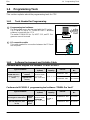
1.4 Programming Tools 1 -9.............................................
1.4.1 Tools Needed for Programming 1 -9..........................
1.4.2 Software Environment and Suitable Cable 1 -9.................
Chapter 2 Specifications and Functions of Control Unit
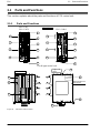
2.1 Parts and Functions 2 -3............................................
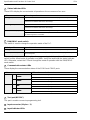
2.1.1 Parts and Functions 2 -3....................................
2.1.2 Tool Port Specification 2 -6..................................
2.1.3 Communication Cassette 2 -6................................
2.2 Input and Output Specifications 2 -7..................................
2.2.1 Input Specifications 2 -7.....................................
2.2.2 Output Specifications 2 -9...................................
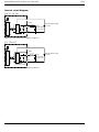
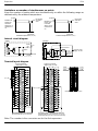
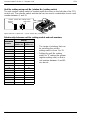
2.3 Terminal Layout Diagram 2 -12........................................
2.3.1 Control Unit (for C32T and C32T2) 2 -12.......................
2.3.2 Control Unit (for C24R2) 2 -12.................................
Chapter 3 Expansion
3.1 Type of Expansion Unit 3 -3.........................................

Table of Contents FPΣ
ii
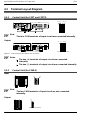
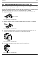
3.2 Expansion Method of Units for FP0 and FPΣ3-4.......................
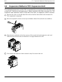
3.3 Expansion Method of FPΣExpansion Unit 3 -5.........................
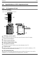
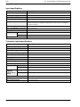
3.4 Specifications of FPΣExpansion Unit 3 -6.............................
3.4.1 FPΣExpansion I/O Unit 3 -6.................................
Chapter 4 I/O Allocation
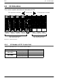
4.1 I/O Allocation 4 -3..................................................
4.1.1 I/O Number of FPΣControl Unit 4 -3..........................
4.1.2 I/O Number of FPΣExpansion Unit (for left side expansion) 4 -4..
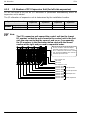
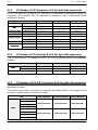
4.1.3 I/O Number of FP0 Expansion Unit (for right side expansion) 4 -5.
4.1.4 I/O Number of FP0 Analog I/O Unit (for right side expansion) 4 -5.
4.1.5 I/O Number of FP0 A/D Conversion Unit
(for right side expansion) 4 -5................................
4.1.6 I/O Number of FP0 I/O Link Unit (for right side expansion) 4 -6...
Chapter 5 Installation and Wiring
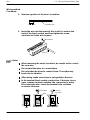
5.1 Installation 5 -3....................................................
5.1.1 Installation Environment and Space 5 -3.......................
5.1.2 Installation and Removal 5 -6................................
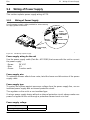
5.2 Wiring of Power Supply 5 -9.........................................
5.2.1 Wiring of Power Supply 5 -9.................................
5.2.2 Grounding 5 -11.............................................
5.3 Wiring of Input and Output 5 -12......................................
5.3.1 Input Wiring 5 -12...........................................
5.3.2 Output Wiring 5 -15..........................................
5.3.3 Precautions Regarding Input and Output Wirings 5 -16...........
5.4 Wiring of MIL Connector Type 5 -17...................................
5.5 Wiring of Terminal Block Type 5 -20....................................
5.6 Safety Measures 5 -22...............................................
5.6.1 Safety Measures 5 -22.......................................
5.6.2 Momentary Power Failures 5 -23..............................
5.6.3 Protection of Power Supply and Output Sections 5 -23...........
5.7 Backup Battery 5 -24................................................
5.7.1 Installation of Backup Battery 5 -24............................
5.7.2 System Register Setting 5 -25.................................
5.7.3 Lifetime of Backup Battery 5 -26...............................

Table of Contents
FPΣ
iii
Chapter 6 High-speed Counter and Pulse Output Functions
6.1 Overview of Each Functions 6 -3.....................................
6.1.1 Three Functions that Use Built-in High-speed Counter 6 -3......
6.1.2 Performance of Built-in High-speed Counter 6 -4...............
6.2 Function Specifications and Restricted Items 6 -5......................
6.2.1 Table of Specifications 6 -5..................................
6.2.2 Function being Used and Restrictions 6 -7.....................
6.2.3 Booting Time 6 -9..........................................
6.3 High-speed Counter Function 6 -10...................................
6.3.1 Overview of High-speed Counter Function 6 -10.................
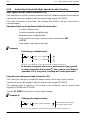
6.3.2 Types of Input Modes 6 -10...................................
6.3.3 Min. Input Pulse Width 6 -12..................................
6.3.4 I/O Allocation 6 -12..........................................
6.3.5 Instructions Used with High-speed Counter Function 6 -13........
6.3.6 Sample Program 6 -16.......................................
6.4 Pulse Output Function 6 -20..........................................
6.4.1 Overview of Pulse Output Function 6 -20.......................
6.4.2 Types of Pulse Output Method 6 -21...........................
6.4.3 I/O Allocation 6 -22..........................................
6.4.4 Control Mode 6 -23..........................................
6.4.5 Instructions Used with Pulse Output Function 6 -24..............
6.4.6 Sample Program for Positioning Control 6 -43...................
6.5 PWM Output Function 6 -56..........................................
6.5.1 Overview of PWM Output Function 6 -56.......................
6.5.2 Instruction Used with PWM Output Function 6 -56...............
Chapter 7 Communication Cassette
7.1 Communication Functions of FPΣ7-3................................
7.1.1 Functions of Communication Cassette 7 -3....................
7.2 Communication Cassette 7 -6........................................
7.2.1 Type of Communication Cassette 7 -6.........................
7.2.2 Names and Principle Applications of the Ports 7 -7..............
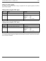
7.2.3 Communication Specifications of Communication Cassette 7 -8..
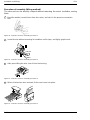
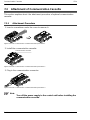
7.3 Attachment of Communication Cassette 7 -10...........................
7.3.1 Attachment Procedure 7 -10..................................

Table of Contents FPΣ
iv
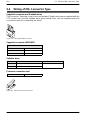
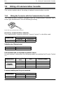
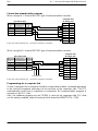
7.4 Wiring of Communication Cassette 7 -11...............................
7.4.1 Wiring the Connector with the Communication Cassette 7 -11.....
7.4.2 Tool for Tightening Communication Connector Terminal Block 7 -12
7.4.3 Wiring Method 7 -12.........................................
7.4.4 Cautions Regarding Wiring 7 -12..............................
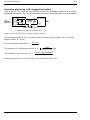
Chapter 8 Communication Function 1 Computer Link
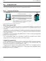
8.1 Computer Link 8 -3.................................................
8.1.1 Overview of Function 8 -3...................................
8.1.2 Explanation of Operation when Using a Computer Link 8 -4......
8.1.3 Format of Command and Response 8 -5......................
8.1.4 Types of Commands that Can Be Used 8 -8...................
8.1.5 Setting the Communication Parameters when
Using a Computer Link 8 -10..........................................
8.1.6 Restriction 8 -10.............................................
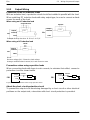
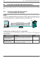
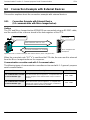
8.2 Connection Example with External Device 8 -11.........................
8.2.1 Connection Example with External Device
(1:1 communication with computer) 8 -11......................
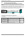
8.2.2 Connection Example with External Device
(1:1 communication with programmable display “GT10/GT30”) 8 -14
8.3 Computer Link (1:N communication) 8 -18..............................
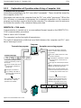
8.3.1 Overview of 1:N Communication 8 -18.........................
8.3.2 Communication Cassette Used for 1:N Communication 8 -18......
8.3.3 Settings of System Register and Unit No. 8 -19..................
8.3.4 Connection with External Device 8 -22.........................
Chapter 9 Communication Function 2 General-purpose
Serial Communication
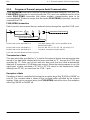
9.1 General-purpose Serial Communication 9 -3..........................
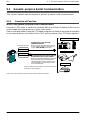
9.1.1 Overview of Function 9 -3...................................
9.1.2 Program of General-purpose Serial Communication 9 -5........
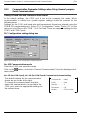
9.1.3 Communication Parameter Settings when Using
General-purpose Serial Communications 9 -6..................
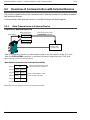
9.2 Overview of Communication with External Devices 9 -8.................
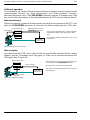
9.2.1 Data Transmission to External Device 9 -8.....................
9.2.2 Receiving Data from External Device 9 -12......................

Table of Contents
FPΣ
v
9.3 Connection Example with External Devices 9 -16........................
9.3.1 Connection Example with External Device
(1:1 communication with Micro-Imagechecker) 9 -16.............
9.3.2 Connection Example with External Device
(1:1 communication with FP series PLC) 9 -22..................
9.4 Data Transmitted and Received with the FPΣ9-29......................
9.5 1:N Communication 9 -31............................................
9.5.1 Overview of 1:N Communication 9 -31.........................
9.5.2 Communication Cassette Used with 1 : N Communication 9 -31...
9.5.3 Setting of System Register 9 -32..............................
9.6 Flag Operations When Using Serial Communication 9 -33................
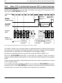
9.6.1 When “STX not exist” is Set for Start Code and “CR” is
Set for End Code 9 -33.......................................
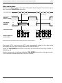
9.6.2 When “STX” is Set for Start Code and “ETX” is Set for
End Code 9 -35.............................................
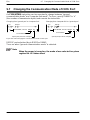
9.7 Changing the Communication Mode of COM. Port 9 -37..................
Chapter 10 Communication Function 3 PLC Link Function
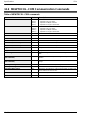
10.1 PLC Link 10 -3......................................................
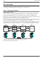
10.1.1 Overview of Function 10 -3...................................
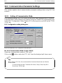
10.2 Communication Parameter Settings 10 -5..............................
10.2.1 Setting of Communication Mode 10 -5..........................
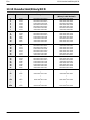
10.2.2 Setting of Unit No. 10 -6......................................
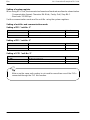
10.2.3 Allocation of Link Relay and Link Register 10 -10.................
10.2.4 Setting the Largest Station Number for a PLC Link 10 -16..........
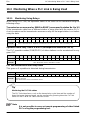
10.3 Monitoring When a PLC Link is Being Used 10 -17........................
10.3.1 Monitoring Using Relays 10 -17.................................
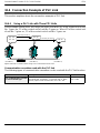
10.4 Connection Example of PLC Link 10 -18.................................
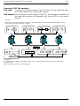
10.4.1 Using a PLC Link with Three FPΣUnits 10 -18....................
10.4.2 Sample Programs 10 -21......................................
10.5 PLC Link Response Time 10 -22.......................................
10.5.1 PLC Link Response Time 10 -22................................
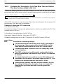
10.5.2 Shortening the Transmission Cycle Time When There are
Stations That Have not been Added to the Link 10 -25.............
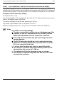
10.5.3 Error Detection Time for Transmission Assurance Relays 10 -26....

Table of Contents FPΣ
vi
Chapter 11 Other Functions
11.1 Analog Potentiometer 11 -3...........................................
11.1.1 Overview of Analog Potentiometer 11 -3........................
11.1.2 Example Showing How the Analog Potentiometers are Used 11 -3.
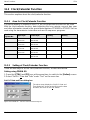
11.2 Clock/Calendar Function 11 -4........................................
11.2.1 Area for Clock/Calendar Function 11 -4.........................
11.2.2 Setting of Clock/Calendar Function 11 -4.......................
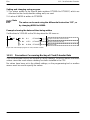
11.2.3 Precautions Concerning Backup of Clock/Calendar Data 11 -5....
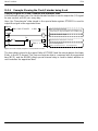
11.2.4 Example Showing the Clock/Calendar being Used 11 -6..........
Chapter 12 Self-Diagnostic and Troubleshooting
12.1 Self-Diagnostic Function 12 -3........................................
12.1.1 LED Display for Status Condition 12 -3.........................
12.1.2 Operation on Error 12 -4......................................
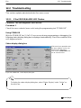
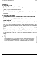
12.2 Troubleshooting 12 -5................................................
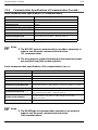
12.2.1 If the ERROR/ALARM LED Flashes 12 -5.......................
12.2.2 If the ERROR/ALARM LED Lights 12 -7........................
12.2.3 If None of the LEDs Light 12 -7................................
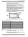
12.2.4 If Outputting does not Occur as Desired 12 -8...................
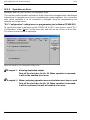
12.2.5 If a Protect Error Message Appears 12 -10.......................
12.2.6 If the Program Mode does not Change to RUN 12 -10.............
12.2.7 If a Transmission Error has Occurred 12 -11.....................
Chapter 13 Specifications
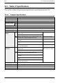
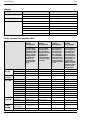
13.1 Table of Specifications 13 -3..........................................
13.1.1 General Specifications 13 -3..................................
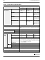
13.1.2 Performance Specifications 13 -5..............................
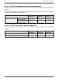
13.2 I/O No. Allocation 13 -10..............................................
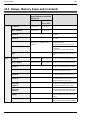
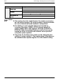
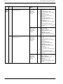
13.3 Relays, Memory Areas and Constants 13 -12............................
13.4 Table of System Registers 13 -14.......................................
13.4.1 System Registers 13 -14......................................
13.4.2 Table of System Registers 13 -16...............................
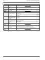
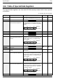
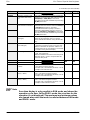
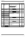
13.5 Table of Special Internal Relays 13 -21..................................
13.6 Table of Special Data Registers 13 -28..................................

Table of Contents
FPΣ
vii
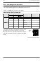
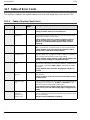
13.7 Table of Error Cords 13 -42............................................
13.7.1 Table of Syntax Check Error 13 -42.............................
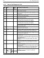
13.7.2 Table of Self-Diagnostic Error 13 -43............................
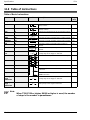
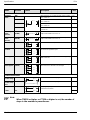
13.8 Table of Instructions 13 -44............................................
13.9 MEWTOCOL-COM Communication Commands 13 -66...................
13.10 Hexadecimal/Binary/BCD 13 -67.......................................
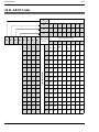
13.11 ASCII Codes 13 -68..................................................
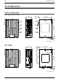
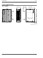
13.12Dimensions 13 -69...................................................
13.12.1 Control Unit 13 -69............................................
13.12.2 Expansion Unit 13 -70.........................................
Index I-1..............................................................
Record of changes R-1..............................................

Before You Start FPΣ
viii
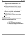
Before You Start
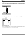
Installation environment
Do not use the FPΣunit where it will be exposed to the following:
Direct sunlight and ambient temperatures outside the
range of 0_Cto55_C/32_F to 131_F.
Ambient humidity outside the range of 30% to 85% RH
and sudden temperature changes causing condensation.
Inflammable or corresive gas.
Excessive vibration or shock.
Excessive airborne dust, metal particles or salts.
Water or oil in any from including spray or mist.
Benzine, paint thinner, alcohol or other organic solvents
or strong alkaline solutions such as ammonia or caustic
soda.
Influence from power transmission lines, high voltage
equipment, power cables, power equipment, radio
transmitters, or any other equipment that would generate
high switching surges.
Static electricity
Before touching the unit, always touch a grounded piece
of metal in order to discharge static electricity.
In dry locations, excessive static electricity can cause
problems.
Cleaning Do not use thinner based cleaners because they deform
the unit case and fade the colors.
Power supplies
An insulated power supply with an internal protective
circuit should be used. The power supply for the control
unit operation is a non-insulated circuit, so if an
incorrect voltage is directly applied, the internal circuit
may be damaged or destroyed.
If using a power supply without a protective circuit,
power should be supplied through a protective element
such as a fuse.

Before You Start
FPΣ
ix
Power supply sequence
Have the power supply sequence such that the power
supply of the control unit turns off before the power
supply for input and output.
If the power supply for input and output is turned off
before the power supply of the control unit, the control
unit will detect the input fluctuations and may begin an
unscheduled operation.
Before turning on the power
Whenturningonthepowerfor thefirsttime,besuretotaketheprecautionsgivenbelow.
When performing installation, check to make sure that
there are no scraps of wiring, particularly conductive
fragments, adhering to the unit.
Verify that the power supply wiring, I/O wiring, and power
supply voltage are all correct.
Sufficiently tighten the installation screws and terminal
screws.
Set the mode selector to PROG. mode.
Before entering a program
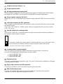
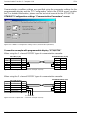
Be sure to perform a program clear operation before entering a program.
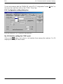
Operation procedure when using FPWIN GR Ver.2
Procedure:
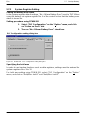
1. Select “Online Edit Mode” on the FPWIN GR
“On line” menu.
2. Select “Clear Program” on the “Edit” menu.
3. When the confirmation dialog box is displayed, click
on “Yes” to clear the program.

Before You Start FPΣ
x
Request concerning program storage
To prevent the accidental loss of programs, the user should consider the following
measures.
Drafting of documents
To avoid accidentally losing programs, destroying files, or
overwriting the contents of a file, documents should be
printed out and then saved.
Specifying the password carefully
The password setting is designed to avoid programs being
accidentally overwritten. If the password is forgotten,
however, it will be impossible to overwrite the program even if
you want to. Also, if a password is forcibly bypassed, the
program is deleted. When specifying the password, note it in
the specifications manual or in another safe location in case
it is forgotten at some point.

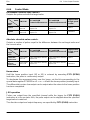
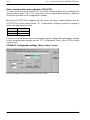
Programming Tool Restrictions
FPΣ
xi
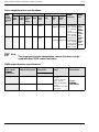
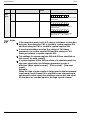
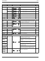
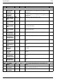
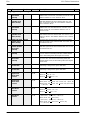
Programming Tool Restrictions
Type of programming tool Instruction used/function restrictions
Windows software
Conforms to IEC61131-3 FPWIN Pro Ver.4 All instructions and functions can be used.
W
indows
software
FPWIN GR Ver.2 All instructions and functions can be used.
W
i
n
d
ows so
f
tware FPWIN GR Ver.1 Not used
MS
-
DOS
software
NPST-GR Ver.4
Not
used
MS
-
DOS
so
f
tware NPST-GR Ver.3
N
ot use
d
AFP1114V2
Handy programming unit
(FP
)
AFP1114
Not
used
y
pg g
(FP programmer) AFP1112A
AFP1112
Not
used
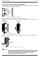
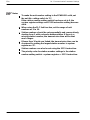
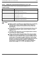
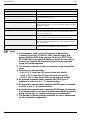
Notes Precautions concerning programming tools
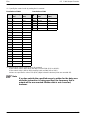
Programming tools used with the FPΣrequire FPWIN Pro Ver. 4 or
later or Ver. 2 or a subsequent version of the FPWIN GR. Please be
aware that other tools cannot be used.
Either “FPWIN Pro Ver.4.1 or later” or “FPWIN GR Ver. 2.1 or later”
are necessary for use the C32T2 and C24R2 types control unit.

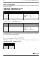
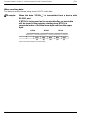
Compatibility with the FP0 FPΣ
xii
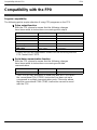
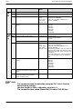
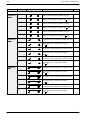
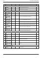
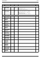
Compatibility with the FP0
Program compatibility
The following points require attention if using FP0 programs on the FPΣ.
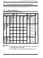
Pulse output function
With the FPΣ, please be aware that the following changes
have been made to instructions concerning pulse output.
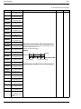
Instruction For the FP0 For the FPΣ
Trapezoidal control F168 (SPD1) F171 (SPDH)
Jog feed F169 (PLS) F172 (PLSH)
Data table control None F174 (SP0H)
Linear interpolation control None F175 (SPSH)
Circular interpolation control None F176 (SPCH)
PWM output F170 (PWM) F173 (PWMH)
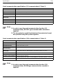
* Linear and circular interpolation control can be used only with the
FPΣControl Unit C32T2.
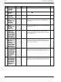
Serial data communication function
With the FPΣ, please be aware that the following changes
have been made to instructions concerning serial data
communication.
Instruction For the FP0 For the FPΣ
Serial data communication F144 (TRNS) F159 (MTRN)
* The F159 (MTRN) instruction is used only with an FPΣin which
the conventional F144 (TRNS) instruction has been set up to
correspond to multiple communication ports. Please be aware
that the conventional F144 (TRNS) instruction cannot be used
with the FPΣ.

Chapter 1
Functions and Restrictions of the Unit
1.1 Features and Functions of the Unit 1 -3................
1.2 Unit Types 1 -6......................................
1.3 Restrictions on Unit Combinations 1 -7.................
1.4 Programming Tools 1 -9..............................

FPΣFunctions and Restrictions of the Unit
1-2

FPΣ1.1 Features and Functions of the Unit
1-3
1.1 Features and Functions of the Unit
Powerful control capabilities
All of the functions of a mid-scale PLC are packed into the compact body size of the
32-point type FP0. A program capacity of 12 k steps is provided as a standard feature,
so you never have to worry about how much memory is left as you’re programming. In
addition, 32 k words are reserved for data registers, so large volumes of data can be
compiled and multiple operations can be processed without running out of memory.
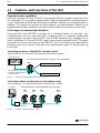
A full range of communication functions
Using the Tool port (RS232C) provided as a standard feature on the main unit,
communication can be carried out with a display panel or computer. Additionally,
communication cassettes with RS232C and RS485 interfaces are available as an
option. Installing a 2-channel RS232C type communicationcassette in the FPΣmakes
it possible to connect two devices with RS232C port. A full lineup of communication
functions means you can also work with 1:N communication and PLC link function (up
to 16 units).
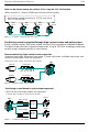
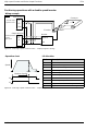
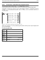
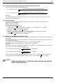
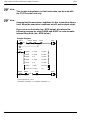
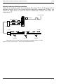
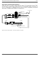
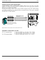
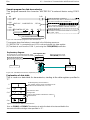
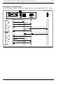
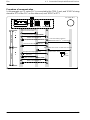
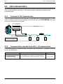
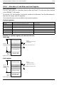
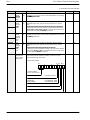
Controlling two devices with RS232C port with one FPΣ
Display panel
The Tool port can be used
to connect a display panel
or other device.
Device with RS232C port
When using the 2-channel RS232C type communication cassette
Two devices with RS232C port can be connected.
Device with RS232C port
FPΣ
Figure 1: Features-communication (RS232C)
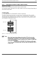
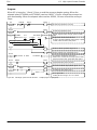
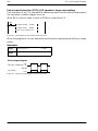
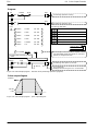
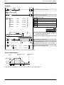
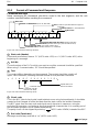
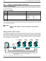
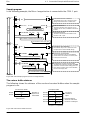
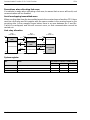
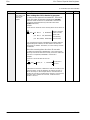
1:N communication possible with up to 99 stations (units)
Communication is possible with up to 99 units.
Commercial adapter
Computer
When using the 1-channel RS485 type communication cassette
FPΣ
No.1 FPΣ
No.2 FPΣ
No.3 FPΣ
No.99
RS485
Figure 2: Features-communication (C-NET)
next page

FPΣ
Functions and Restrictions of the Unit
1-4
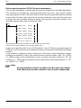
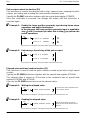
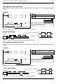
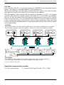
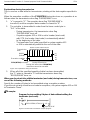
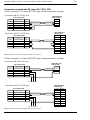
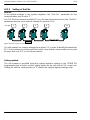
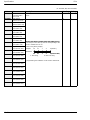
Data can be shared among up to 16 FPΣunits using
the PLC link function.
Data can be shared among the various PLCs using the PLC link function.
When using the 1-channel RS485 type communication cassette
FPΣ
No.1 FPΣ
No.2 FPΣ
No.3 FPΣ
No.16
RS485
Figure 3: Features-communication (PLC link)
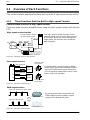
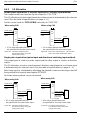
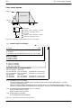
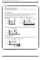
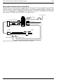
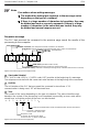
Positioning control supported through high-speed counter and pulse output
A high-speed counter and pulse output functions are provided as standard features.
The pulse output function supports frequencies of up to 100 kHz, enabling positioning
control using a stepping motor or servo motor.
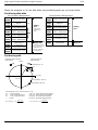
Measurement using high-speed counter supported
Encoder
Single phase: Max. 50 kHz, Two-phase: Max. 20 kHz
Encoder
FPΣ
Increment input mode, decrement input mode, 2-phase input mode, individual input mode, and
direction discrimination mode are supported.
Pulse input
Pulse input
Figure 4: Features-High-speed counter
FPΣ
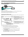
Positioning control based on pulse output supported
Pulse output
1-channel: Max. 100 kHz, 2-channel: Max. 60 kHz
Mortor
driver
CW/CCW and Pulse/sign outputs are supported.
Pulse output
Mortor
driver
Mortor
Mortor
Figure 5: Features-Pulse output

FPΣ1.1 Features and Functions of the Unit
1-5
Analog control supported
An analog potentiometer (volume dial) is provided as a standard feature. This can be
used in applications such as analog timers, without using the programming tools. An
analog unit is also available as the intelligent unit.

FPΣ
Functions and Restrictions of the Unit
1-6
1.2 Unit Types
This section explains the type of unit used with the FPΣand about the optional
communication cassette.
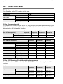
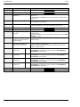
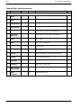
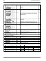
1.2.1 FPΣControl Unit
Name Number of I/O points Part No. Product No.
Input: 16 points/Transistor output: 16 points FPG-C32T AFPG2543
FPΣControl unit Input: 16 points/Transistor output: 16 points FPG-C32T2 AFPG2643
Input: 16 points/Relay output: 8 points FPG-C24R2 AFPG2423
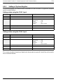
1.2.2 FPΣExpansion Unit
Name Number of I/O points Part No. Product No.
FPΣexpansion I/O unit Input: 32 points/Transistor output: 32 points FPG-XY64D2T AFPG3467
* The FPΣexpansion I/O unit can be used for “FPG-C32T2 and FPG-C24R2” FPΣ
control units.
1.2.3 Units for FP0 and FPΣ
The FPΣcan be used the FP0 series expansion I/O unit, power supply unit, and
intelligent unit.
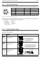
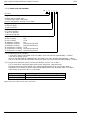
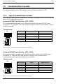
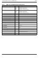
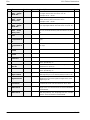
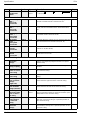
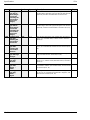
1.2.4 Communication Cassette
A detachable communication cassette (optional) should be used when using the
various functions such as the computer link, serial data communication, and PLC link
functions.
Name Description Part No. Product No.
FPΣCommunication
cassette 1-channel
RS232C type
This communication cassette is a 1-channel unit with
a five-wire RS232C port. It supports 1 : 1 computer
links and general-purpose serial communication. RS/
CS control is possible. FPG-COM1 AFPG801
FPΣCommunication
cassette 2-channel
RS232C type
This communication cassette is a 2-channel unit with
a three-wire RS232C port. It supports 1 : 1 computer
links and general-purpose serial communication.
Communication with two external devices is possible. FPG-COM2 AFPG802
FPΣCommunication
cassette 1-channel
RS485 type
This communication cassette is a 1-channel unit with
a two-wire RS485 port. It supports 1 : N computer
links(C-NET),general-purposeserialcommunication,
and a PLC link. FPG-COM3 AFPG803

FPΣ1.3 Restrictions on Unit Combinations
1-7
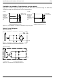
1.3 Restrictions on Unit Combinations
This section contains restrictions on unit combinations.
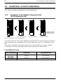
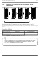
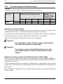
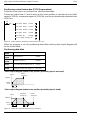
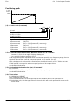
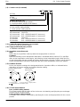
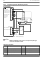
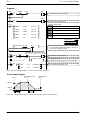
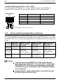
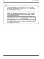
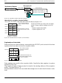
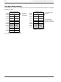
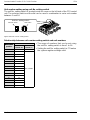
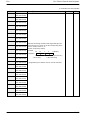
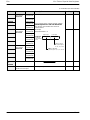
1.3.1 Restrictions on the Number of Expansion Units
(for FP0 expansion unit)
Control unit Unit 1 for expansion
(Maximum possible
expansion is with a
total of three units)
Unit 2 for expansion Unit 3 for expansion
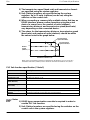
Figure 6: Restriction on unit combinations
Up to three expansion units can be added at the right of the FPΣ, these expansion units being
either expansion units or intelligent units from the earlier FP0 series, or a combination of the
two.
There are no restrictions on the type and the order in which expansion units are installed.
A combination of relay output types and transistor output types is also possible.
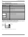
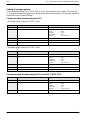
Controllable I/O Points
Type of control unit Number of I/O points when using
control unit Number of I/O points when using
FP0 expansion unit
FPG-C32T
FPG-C32T2 32 points Max. 128 points
FPG-C24R2 24 points Max. 120 points
Page is loading ...
Page is loading ...
Page is loading ...
Page is loading ...
Page is loading ...
Page is loading ...
Page is loading ...
Page is loading ...
Page is loading ...
Page is loading ...
Page is loading ...
Page is loading ...
Page is loading ...
Page is loading ...
Page is loading ...
Page is loading ...
Page is loading ...
Page is loading ...
Page is loading ...
Page is loading ...
Page is loading ...
Page is loading ...
Page is loading ...
Page is loading ...
Page is loading ...
Page is loading ...
Page is loading ...
Page is loading ...
Page is loading ...
Page is loading ...
Page is loading ...
Page is loading ...
Page is loading ...
Page is loading ...
Page is loading ...
Page is loading ...
Page is loading ...
Page is loading ...
Page is loading ...
Page is loading ...
Page is loading ...
Page is loading ...
Page is loading ...
Page is loading ...
Page is loading ...
Page is loading ...
Page is loading ...
Page is loading ...
Page is loading ...
Page is loading ...
Page is loading ...
Page is loading ...
Page is loading ...
Page is loading ...
Page is loading ...
Page is loading ...
Page is loading ...
Page is loading ...
Page is loading ...
Page is loading ...
Page is loading ...
Page is loading ...
Page is loading ...
Page is loading ...
Page is loading ...
Page is loading ...
Page is loading ...
Page is loading ...
Page is loading ...
Page is loading ...
Page is loading ...
Page is loading ...
Page is loading ...
Page is loading ...
Page is loading ...
Page is loading ...
Page is loading ...
Page is loading ...
Page is loading ...
Page is loading ...
Page is loading ...
Page is loading ...
Page is loading ...
Page is loading ...
Page is loading ...
Page is loading ...
Page is loading ...
Page is loading ...
Page is loading ...
Page is loading ...
Page is loading ...
Page is loading ...
Page is loading ...
Page is loading ...
Page is loading ...
Page is loading ...
Page is loading ...
Page is loading ...
Page is loading ...
Page is loading ...
Page is loading ...
Page is loading ...
Page is loading ...
Page is loading ...
Page is loading ...
Page is loading ...
Page is loading ...
Page is loading ...
Page is loading ...
Page is loading ...
Page is loading ...
Page is loading ...
Page is loading ...
Page is loading ...
Page is loading ...
Page is loading ...
Page is loading ...
Page is loading ...
Page is loading ...
Page is loading ...
Page is loading ...
Page is loading ...
Page is loading ...
Page is loading ...
Page is loading ...
Page is loading ...
Page is loading ...
Page is loading ...
Page is loading ...
Page is loading ...
Page is loading ...
Page is loading ...
Page is loading ...
Page is loading ...
Page is loading ...
Page is loading ...
Page is loading ...
Page is loading ...
Page is loading ...
Page is loading ...
Page is loading ...
Page is loading ...
Page is loading ...
Page is loading ...
Page is loading ...
Page is loading ...
Page is loading ...
Page is loading ...
Page is loading ...
Page is loading ...
Page is loading ...
Page is loading ...
Page is loading ...
Page is loading ...
Page is loading ...
Page is loading ...
Page is loading ...
Page is loading ...
Page is loading ...
Page is loading ...
Page is loading ...
Page is loading ...
Page is loading ...
Page is loading ...
Page is loading ...
Page is loading ...
Page is loading ...
Page is loading ...
Page is loading ...
Page is loading ...
Page is loading ...
Page is loading ...
Page is loading ...
Page is loading ...
Page is loading ...
Page is loading ...
Page is loading ...
Page is loading ...
Page is loading ...
Page is loading ...
Page is loading ...
Page is loading ...
Page is loading ...
Page is loading ...
Page is loading ...
Page is loading ...
Page is loading ...
Page is loading ...
Page is loading ...
Page is loading ...
Page is loading ...
Page is loading ...
Page is loading ...
Page is loading ...
Page is loading ...
Page is loading ...
Page is loading ...
Page is loading ...
Page is loading ...
Page is loading ...
Page is loading ...
Page is loading ...
Page is loading ...
Page is loading ...
Page is loading ...
Page is loading ...
Page is loading ...
Page is loading ...
Page is loading ...
Page is loading ...
Page is loading ...
Page is loading ...
Page is loading ...
Page is loading ...
Page is loading ...
Page is loading ...
Page is loading ...
Page is loading ...
Page is loading ...
Page is loading ...
Page is loading ...
Page is loading ...
Page is loading ...
Page is loading ...
Page is loading ...
Page is loading ...
Page is loading ...
Page is loading ...
Page is loading ...
Page is loading ...
Page is loading ...
Page is loading ...
Page is loading ...
Page is loading ...
Page is loading ...
Page is loading ...
Page is loading ...
Page is loading ...
Page is loading ...
Page is loading ...
Page is loading ...
Page is loading ...
Page is loading ...
Page is loading ...
Page is loading ...
Page is loading ...
Page is loading ...
Page is loading ...
Page is loading ...
Page is loading ...
Page is loading ...
Page is loading ...
Page is loading ...
Page is loading ...
Page is loading ...
Page is loading ...
Page is loading ...
Page is loading ...
Page is loading ...
Page is loading ...
Page is loading ...
Page is loading ...
Page is loading ...
Page is loading ...
Page is loading ...
Page is loading ...
Page is loading ...
Page is loading ...
Page is loading ...
Page is loading ...
Page is loading ...
Page is loading ...
Page is loading ...
Page is loading ...
Page is loading ...
Page is loading ...
Page is loading ...
Page is loading ...
Page is loading ...
Page is loading ...
Page is loading ...
Page is loading ...
Page is loading ...
Page is loading ...
Page is loading ...
Page is loading ...
Page is loading ...
Page is loading ...
Page is loading ...
Page is loading ...
Page is loading ...
Page is loading ...
Page is loading ...
Page is loading ...
Page is loading ...
Page is loading ...
Page is loading ...
Page is loading ...
Page is loading ...
Page is loading ...
Page is loading ...
Page is loading ...
Page is loading ...
Page is loading ...
Page is loading ...
Page is loading ...
-
 1
1
-
 2
2
-
 3
3
-
 4
4
-
 5
5
-
 6
6
-
 7
7
-
 8
8
-
 9
9
-
 10
10
-
 11
11
-
 12
12
-
 13
13
-
 14
14
-
 15
15
-
 16
16
-
 17
17
-
 18
18
-
 19
19
-
 20
20
-
 21
21
-
 22
22
-
 23
23
-
 24
24
-
 25
25
-
 26
26
-
 27
27
-
 28
28
-
 29
29
-
 30
30
-
 31
31
-
 32
32
-
 33
33
-
 34
34
-
 35
35
-
 36
36
-
 37
37
-
 38
38
-
 39
39
-
 40
40
-
 41
41
-
 42
42
-
 43
43
-
 44
44
-
 45
45
-
 46
46
-
 47
47
-
 48
48
-
 49
49
-
 50
50
-
 51
51
-
 52
52
-
 53
53
-
 54
54
-
 55
55
-
 56
56
-
 57
57
-
 58
58
-
 59
59
-
 60
60
-
 61
61
-
 62
62
-
 63
63
-
 64
64
-
 65
65
-
 66
66
-
 67
67
-
 68
68
-
 69
69
-
 70
70
-
 71
71
-
 72
72
-
 73
73
-
 74
74
-
 75
75
-
 76
76
-
 77
77
-
 78
78
-
 79
79
-
 80
80
-
 81
81
-
 82
82
-
 83
83
-
 84
84
-
 85
85
-
 86
86
-
 87
87
-
 88
88
-
 89
89
-
 90
90
-
 91
91
-
 92
92
-
 93
93
-
 94
94
-
 95
95
-
 96
96
-
 97
97
-
 98
98
-
 99
99
-
 100
100
-
 101
101
-
 102
102
-
 103
103
-
 104
104
-
 105
105
-
 106
106
-
 107
107
-
 108
108
-
 109
109
-
 110
110
-
 111
111
-
 112
112
-
 113
113
-
 114
114
-
 115
115
-
 116
116
-
 117
117
-
 118
118
-
 119
119
-
 120
120
-
 121
121
-
 122
122
-
 123
123
-
 124
124
-
 125
125
-
 126
126
-
 127
127
-
 128
128
-
 129
129
-
 130
130
-
 131
131
-
 132
132
-
 133
133
-
 134
134
-
 135
135
-
 136
136
-
 137
137
-
 138
138
-
 139
139
-
 140
140
-
 141
141
-
 142
142
-
 143
143
-
 144
144
-
 145
145
-
 146
146
-
 147
147
-
 148
148
-
 149
149
-
 150
150
-
 151
151
-
 152
152
-
 153
153
-
 154
154
-
 155
155
-
 156
156
-
 157
157
-
 158
158
-
 159
159
-
 160
160
-
 161
161
-
 162
162
-
 163
163
-
 164
164
-
 165
165
-
 166
166
-
 167
167
-
 168
168
-
 169
169
-
 170
170
-
 171
171
-
 172
172
-
 173
173
-
 174
174
-
 175
175
-
 176
176
-
 177
177
-
 178
178
-
 179
179
-
 180
180
-
 181
181
-
 182
182
-
 183
183
-
 184
184
-
 185
185
-
 186
186
-
 187
187
-
 188
188
-
 189
189
-
 190
190
-
 191
191
-
 192
192
-
 193
193
-
 194
194
-
 195
195
-
 196
196
-
 197
197
-
 198
198
-
 199
199
-
 200
200
-
 201
201
-
 202
202
-
 203
203
-
 204
204
-
 205
205
-
 206
206
-
 207
207
-
 208
208
-
 209
209
-
 210
210
-
 211
211
-
 212
212
-
 213
213
-
 214
214
-
 215
215
-
 216
216
-
 217
217
-
 218
218
-
 219
219
-
 220
220
-
 221
221
-
 222
222
-
 223
223
-
 224
224
-
 225
225
-
 226
226
-
 227
227
-
 228
228
-
 229
229
-
 230
230
-
 231
231
-
 232
232
-
 233
233
-
 234
234
-
 235
235
-
 236
236
-
 237
237
-
 238
238
-
 239
239
-
 240
240
-
 241
241
-
 242
242
-
 243
243
-
 244
244
-
 245
245
-
 246
246
-
 247
247
-
 248
248
-
 249
249
-
 250
250
-
 251
251
-
 252
252
-
 253
253
-
 254
254
-
 255
255
-
 256
256
-
 257
257
-
 258
258
-
 259
259
-
 260
260
-
 261
261
-
 262
262
-
 263
263
-
 264
264
-
 265
265
-
 266
266
-
 267
267
-
 268
268
-
 269
269
-
 270
270
-
 271
271
-
 272
272
-
 273
273
-
 274
274
-
 275
275
-
 276
276
-
 277
277
-
 278
278
-
 279
279
-
 280
280
-
 281
281
-
 282
282
-
 283
283
-
 284
284
-
 285
285
-
 286
286
-
 287
287
-
 288
288
-
 289
289
-
 290
290
-
 291
291
-
 292
292
-
 293
293
-
 294
294
-
 295
295
-
 296
296
-
 297
297
-
 298
298
-
 299
299
-
 300
300
-
 301
301
-
 302
302
-
 303
303
-
 304
304
-
 305
305
-
 306
306
-
 307
307
-
 308
308
-
 309
309
-
 310
310
-
 311
311
-
 312
312
-
 313
313
-
 314
314
-
 315
315
-
 316
316
-
 317
317
-
 318
318
-
 319
319
-
 320
320
-
 321
321
-
 322
322
-
 323
323
-
 324
324
-
 325
325
-
 326
326


NAiS FP Series User manual
- Type
- User manual
- This manual is also suitable for
Ask a question and I''ll find the answer in the document
Finding information in a document is now easier with AI
Other documents
-
Makita FP2 User manual
-
Panasonic C32CT User manual
-
Panasonic Power Supply KW4S User manual
-
Mitsubishi Electric F940GOT-SWD-E User manual
-
-
American Time DSY261RSAE Owner's manual
-
-
-
 Redexim Double Disc Overseeder 2230A Owner's manual
-
