Page is loading ...

•
•
BRISTOL WORKSHOP MANUAL
TYPE 407
and
408
(UP TO CHASSIS No. 408/7200)
BRISTOL
CARS
FILTON
-
BR
ISTOL -
ENGLAND

LIST
OF
CONTENTS
Page
VIEW
OF
BRISTOL
TYPE
407 CAR I
II
• VIEW
OF
BR
ISTOL
TYPE
408
CAR
v
SPECIF
I
CAT
I
ONS
VI
RECOMMENDED LUBRICANTS 3
ENGINE
R.H. V
iew
of
Engine
and
Transmission
6
L.H.
V
iew
of
Engine
and
Transmission
7
Engine
Special
Tools
9
Engine
and
Transmission
Torque
Referenc
es
9
Removal
of
Eng
ine
and
Transmission
11
Cylinder
Blo
ck
12
Cylinder
Head and
Valve
Operating
14
Crankshaft.
Pistons
and
Connecti
ng
Rod
s
22
Engine Lub
ricaeion
26
Eng
ine
Cooling
System
26
Fuel
Supply
System
28
Carburettors
29
IGNITION SYSTEM
50
TORQUE-FLITE
TRANSMI
SS
I
ON
1
BRAKES SYSTEM 1
PROPELLOR
SHAFT 12
FRONT
SUSPENSION 13
STEER
I
NG
17
REAR AXLE
AND
REAR SUSPENSION 19
• E
LEC
TR
ICAL 27
MA
INTENANCE CHART
39
HEATI
NG
AND
VENTILATING
41
( i)

•
Ove
r a
ll
Le
ngth
......
.....
.
....
........
199
inches
Overall
Height
(Unl
ade
n)
...........
60
mc
he
s
Ove
ra
ll
Width
............
.....
....
.
...
68
inches
Ground
Clearance
(Unl
ade
n)
.....
.
6;
i
nc
h
es
Kerb
Wei
gk
..............
3584
Iba
Bristol
Type
40'1'
Car
•
Hi

•
OV
e
rall
Le
ngth
...
"
.................
193%
in
ches
Overall
H
eig
ht (Unladen)
.....
...
.
..
59
inc
hes
Ov
erall Width
........................
68 inch
es
Gr
ou
nd
Clear
an
ce
(U
nladen
)..
.....
6%
inches
K
erb
Weight
...............
3528 lb.
Bristol
Type
408
Mk
.l
Car
•
v

SP
E
CIFICA
TI
ON
DIMENSI
ONS
Wh
eel
Base
F ront
Track
Rea
r
Track
Turning
Circle
Gro
und
Clearance
- (
Unladen)
Overa
ll
He
ight
-
(Unlad
en)
...
Ove
rall
Length
Kerb
Weight
...
C
HA
SS
IS
..
.
9ft
.
Sins.
4ft.
Sins.
4ft.
6}
in
s.
39ft
.
6ins.
6,ins.
5ft.
Oin
s.
16ft.
7in
5 .
3584
l
bs
.
Steel
sh
eet
co
n
str
uc
ti
on.
Ri
gi
d b
ox
sec
ti
on
side
me
mb
e r s
of
6i
i
nch
depth
with
thr
ee
cross
m
embers.
Op
e n p
rope
ll
or
sh
aft
. Sm
iths
b
ev
elift
ja
cking
syste
m us
in
g
built
in
j
ac
king
po
i
nt
s .
FRONT SUSPENS
IO
N
Inde
pendent
by
wis
h
bo
n
es
with
coil
s
prin
gs,
hy
draulic
tel
escop
ic
absorbers.
tersional
anti
-
roll
bar.
R
EAR
SU
SPENS
IO
N
Longitudinal
tors
i
on
bars
abso
rbers.
W
atts
linka
ge
.
ST
EER
I
NG
, .
w
it
h el
ectrically
adjus
tab
le
telesco
pic
shock
Ma
rles
worm-type
steer
ing
. 17
in
c h
2-spoke
adjustab
le
safe
t y d
es
ign
stee
r
in
g wh
ee
l.
Vl
•
•

•
•
BRAKES
Dunlop
hydraulic
self
adjusting
servo-assisted
disc
brakes
on
all
wheels.
Disc
diameters
11!
inch.
Pull
up
type
handbrake
cable
and
rod
operating.
WHEELS
AND
TYRES
Dunlop
pressed
steel
perforated
bolt-on
disc
wheels.
wide
base
rims,
Dunlop
R.S.5
6.00
x 16
tyres
and
tubes
.
Normal
cruising
Sustained
high
speeds
Front
and
R
ear
-
28
p.s.i.
Front
and
Rear
-
33
p.s.i.
ENGINE
E
ight
cylinder
90°
VEEwithoverheadpushrodoperated
valves;
mechanical
tappets.
Canada
Chrysler
VS.
Bore
3.88
inch
(
98
.
55
M/M).
Stroke
3.
31
inch
(84
.07
M/M).
Capacity
313
eu.
inc
h (
5130
e .c .
).
Compression
Ratio
9.0
to 1.
Power
Outp
ut
250
bhp
at
4400
rpm.
Maximum
to
rq
ue
240
lb.
ft.
at
2800
rpm.
Cast
iron
cy
li
nder
block
and
cy
lind
er
head
s;
specia
l
highlif
t
camshaft.
chain
driven
and
supported
in
five
main
beari
n
gs
;
aluminium
pistons
and
fo
rge
- s
teel
connecting
rods;
forge
-
steel
crankshaft
statica
lly
and
dynami-
cally
balanced;
s
upp
orted
in
five
main
bearings.
Lub
rication
system
by
rotary-type
oil
pump
with
integra
l
relief
valve
and
by
-
pass
type
oil
filter.
Carter
4
choke
downdraft
carb
u
rettor
,
automatic
choke
f
or
cold
starting,
manifold
heat
contro
l
valve
f
or
rapid
warm
up
.
Large
paper
element
air
cleaner/
sile
n
cer
.
TRANSMISSION
Ch
rysler
torque
- f
li
te,
three
forward
s
peeds
and
reverse
automatic
tran
s -
m i
ssion,
with
fl
uid
torque
converter,
variable
ratio
drive,
incorporating
i
nter
-
mediate
gear
ho
l
d,
permitt
i
ng
engine
braking.
Gears
selected
by
ill
u
minated
push
buttons
mounted
on
facia
pa
ne
l.
Low
Intermediate
High
Reverse
8.1
4.8
3.31
7.28
Torque
conver
t
er
stalled
ratio
on
low,
intermediate
and
reverse
gears
2.2
to
1.
-1-

HEATING AND
VENTILATING
Built-in
heater
system;
fresh
air
at
desired
volume
or
temperature,
lOcor-
porating
screen
demisting
and
defrosting,
controls
on
facia
panel,
separate
cold
air
system
.
FUEL
SYSTEM
Carter
mechanical
pump.
Tank
mounted
behind
rear
seats
.
Capacity
18
gallons
(Imp)
82
l
itres
including
2~
gallons
(111itres)
reserve
su
pply,
controlled
by
switch
on
facia
panel.
Lockable
fi
ll
er
cap.
RADIATOR
Pressure
vent
141bs/sq
.
inch
with
an
oil
cooler
for
the
transmission
permanently
embodied
into
the
bottom
tank
of
the
radiator
and
provision
in
the
h
eader
tank
for
a
thermostat
switc
h
controlling
the 1!Kenl
owe
l1
fans.
Capacity
...
ELEC
TRI
CAL
36
Imperial
Pints
(20.46
l
itres
)
(Includes
the
heater
of
the
car)
Lucas
12
volt
system.
Current
is
supplied
by
a
large
capacity
air
coo
l
ed
generator
in
conjunction
with
a
voltage
regu
l
ator
with
automatic
cut
-
out
and
a
12
volt
72
ampere
battery.
-2
-
•
•

•
•
ENG
INE AND CHASSIS
RECOMMENDED
LUBRICA
NTS AND
CAPAC
ITIES
ENGINE
CAPAC
I
TY
Including the Oil
Filter
10
pints
(Imp.)
Not
including
the
Oil
Filter
8
pints
(Imp.)
(4.55
Litres)
Above
32
0p
ENGINE
LUBRIC
ATION
Mobiloi
l
Specia
l IOW/30
Esso
Extra
Motor
Oil
20W/30
Ene
rgo
l SAE.
30
or·
Energo
l
Visco
Static
She
ll
X-IOO-30
or
Shell
X_lOO
Mult
igra
de
IOW
/30
Castrolite
Advanced Hav
oline
lOW
130
or
Advanced
Havo
li
ne
30
Mobiloil
Special
IOW/30
-
Esso
Extra
Motor
Oil
20W/30
Energol
SAE 20W
-3-
or
Energol
Visco
Sta
ti
c
Shell X-
lOO
20/20W
or
Shell
X-lOO
Multigrade
IOW
/30
Castrolite
Advanced
Hav
oline
lOW
/30
MobHoil
Specia
l
IOW
/30
Esso
Extra
Motor
Oil
20W
/30
Energo
l SAE
IOW
or
Energo
l
Visco
Stat
ic
She
ll
X- lOO-IOW
or
She
ll
X-
lOO
M
ult
igrade
IOW/30
Castrolite
Adva
nc
ed
Ha
voline
IOW/3
D
Mobiloil
Specia
l
SAW
5W
Esso
extra
Motor
Oil
5W
/20

AUTOMA
TI
C TRANSMI
SS
I
ON
CAPACITY
16
pints
(Imp.)
(9
.0
9
Lit
res
)
R
EAR
AXLE CAPACITY
3 pi
nts
(Imp.)
(
1.
7
Litres
)
STEER
I
NG
BOX CAPAC
IT
Y
,pint
(lmp
.)
(0.
28
Litr
es
)
- 4 -
Ene
rgol SAE
5W
She
ll
X-
lOO
Mul
tigrade
5W
120
Castrol
i
te
Advanced
H
avoline
IOW
13
0
AUTOMATIC TR
ANS
MI
SS
I
ON
LUB
RI
CA
TIO
N
M
obi
lfluid 200
E
sso
A
ut
omatic
Trans
mi
ssio
n
Fluid
55
Ene
rg
ol A
TF
.
Type
A.
She
ll
Donax
T6
Ca
st
rol
TQ
R
egent
3528
Texamatic
F
luid.
REAR AXLE LUBRICATION
M
obi
lube
GX
.90
Esso
Gear
Oil
GP.90
(Above
_IO
oF
)
Esso
Gear
Oil
GP.80
(Below _
10°F
)
Ene
rgol SAE 90
EP
She
ll
Spi
rax
90
EP
Castro
l Hypoy
R
ege
nt
Universal
Thurban
90
S
TEERI
NG
BOX. THROTTLE
CONTROLS. H
AN
DBRAKE
CABLE
LUBRICATION.
Mobilube GX.90
Esso
Gear
Oil
GP.90
Energo
l SAE
90
EP.
Sp
ira.
90
EP
.
Castol
Hypoy
R
egent
Universa
l
Thurban
90
DIS
TRIBUT
OR
AN
D G
ENE
RATOR
LU
BR
ICATION
Mobil
As
engine
Esso
As
en
gi
ne
B.
P.
As
eng
in
e
Sh
ell
As
engine
Castrol
Every
man
Oil
R
egent
Ha
vo
line
20/20W
•
•

•
•
BRAKE FLUID
POINTS NOT REQUIRING
LUBRICATION SERVICE.
-5
-
EXHAUST MANIFOLD
HEAT
CON-
TROL
VALVE LUBRICATION.
Graphited
Kerosene
FRONT
WHEEL HUBS.
REAR
SUS-
PENSION UNITS.
PROPELLOR
SHAFT
JOINTS. HANDBRAKE
COMPEN-
SATOR.
REAR
AXLE HUBS.
Mobilgrea
se
M.P
.
Esso
Multi
-
purpose
Grease
H.
E
nergrease
L.2.
Shell
Retioax
A
Casrrolease
LM
Regent
Marfax
Multi-purpose
Grea
se
2
Dunlop
Disc
Brake
Fluid.
Specification
SAE
70Rl
and SAE 70R3
ENGINE
Water
Pump
.
Starter
Motor
Bearings.
Automatic
Choke
Linkage.
Fen
Belt
Idler
Pulley.
CHASSIS
Steering
Joints
.
Front
Suspension
To
p
and
Bottom
Joints.
Wishbone
Bushes.
Steering
Idler
Box
Bushes
.
Brake
Pedal
Bushes.
Steering
Column
Bushes.
Rear
Suspension
Arms.
Watts
Linkage
- R
ear
Suspension.

•
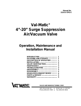
Ftg.~
R.II. View or Engine
and
Transmission
KEY TO
FIG.
5
l.
Coi
l.
10.
Fuel
Filter.
2.
Carburettor.
1l.
Engine
Mounting.
3.
Carburettor
Air
Cleaner.
1
2.
Oil
Filter.
4.
Engi
ne
Dipstick.
1
3.
Transmission
Drain
Plug.
5. Gen
erator
Be
lt
Adjustment
14.
Ex
hau
st
Manifold.
Strap.
15
. Manifold Heat
Control
Valve.
6.
Wa
t
er
Pu
mp
.
16
. T r
ansmission
Dips
ti
ck and
Oil
7.
Idl
er
Pull
ey
Ad
ju
s
tm
ent
Bracket.
Fill
er
Tube.
•
8.
Idler Pulley.
17.
S
parking
Pl
u
gs
and
L
ea
ds.
9.
Fuel
Pump.
1
8.
S
mog
Pack.
-6-

•
•
Fig.6
L.I-I
. View
of
Endne
and l 'ransmJsston
KEY
TO
FIG. 6
1.
Generator.
2. Oil
Fi
lle
r
Pipe
Cap
Air
Cleaner.
3.
Distributor.
4.
Sparking
Plugs
and
Leads.
5.
Transmission
Unit.
S.
Ex
haust
Manifold.
7.
S
tarter
Motor
.
S.
Engi
ne
Mounting.
9.
Oil
Pan
(Sump).
-7-

313 Cu In. Engine
(E
nd
Secti
onal View)
- 8-
•
•

•
•
ENGI
NE
SPEC
I
AL
TOOLS
P i
sto
n
Ring
Compressor
.
Drive
r - Camshaft
We
lch P lug.
Tap
p
et
Bore
R
eamer.
Piston
Pin
Rea
me
r.
C-
385
C-897
C-
3028
C-3049
C-
3052
C-3053
C- 3132A
C-3221
C-3422A
C-
3427
C-3430
C-
3433
C-3466
C-3586
C-3695
C-3927
Distri
b
utor
Drive
Sh
aft
Bus
h
ing
Pu
ll
er
.
Distri
b
utor
Drive
Sh
aft
Bus
hing In
sta
ll
er
.
Cams
haft
Bear
ing R
emover
and
I
nsta
ll
er
.
Pi
sto
n R
emover
and
I
nsta
ll
er
.
Compressor
- Val
ve
Spr
i
ng
.
Val
ve
Guide R
eamer
.
030
o/s
.
Val
ve
Guide
Reamer
.015
o/s
.
Va
l
ve
G
uid
e R
eamer
.005
o/s.
Engine
Li
f
ting
Brac
k
et.
Pisto
n R ing
Installer
.
Co
m
pressor
-
Roc
k
er
Arm
V
al
ve
Sp
ring.
Gauge -Val
ve
Stem
Le
n
gt
h.
TORQUE R
EFERENCE
ENGINE
Cylinder
Head
Bolt
lntake Manifold
Bo
lt
M
ain
Bearing
Cap
Bo
lt
Connecting
Rod
Nut - P
lain
Cranks
haft
Bolt
Camshaft
Spcocket
R
et
a
iner
Screw
Cams
h
aft
Thrust
Plate
Screw
Chain
Case
CO\'er (
Cast
)
Bolt
Water
Outlet
El
b
ow
Bolt
Rocker
COVf!r
Attac
h
me
nt
Bo
lt
Carbo
to
Intake M
anifol
d Nut
Water
Pump
Attachme
nt BoLt
F u
el
Pump
Attach
m
ent
Bolt
Fan
Belt
Idl
er
Pu
ll
ey
Nut
Spark
Plug
Starte
r Mounting
Bo
lt
Generator
Bracket
Bo
lt
Generator
Mounting
Nut
-9-
Ft/
l
bs.
inch/ l
bs
.
85
30
85
45
135
35
15
35
35
3
7
30
30
45
30
50
50
20

Ft
/lb
• .
inc
h/
Ib
s.
Generator
Adj. Strap
Bolt
(
Eng
ine End) 30
Generator
Adju
st
ing
Bo
lt (Gene
ra
tor
End) 15
Di
s
tribu
tor
Vacuum
L ine
Tube
Nut 95 •
Di
stri
hu
tor
Cl
amp
Ro
lt
15
Exha
usl Manifold Nuts and
Bo
lt
s 30
Exha
u
st
Pipe
Flan
ge
Nut 40
Manifold
Heal
Co
n
tro
l
Co
unterw
eight
Bolt
50
Oil
Fi
lt
er
Case
Centre
Bolt
30
O
il
Pan
(Sump) D
rai
n
Plug
35
Oil
Pan
(Sum
p)
Attachment
Bolt
15
Oil
Pump
Attachment
B
olt
35
Oil Pump
Cover
Bolt
10
TOR
QUEFLlTE
TRANS
MI
SS
I
ON
Trans.
Case
to
Torq
ue
Co
n
ver
te
r H
ousi
ng
Bolt
40
Exte
ns ion
to
Trans.
Case
Bo
lt
25
Oil
Pan
(
Su
mp) Bolt 175
Torq
ue
Conve
rt
er
H
ousi
ng
to
Bl
oc
k 30
Torq
ue
Co
n
verter
to
C
rank
sh
aft
Nut 55
Co
n
verter
Dra
in
Pl
ug
130
Converter
Du
st
Cover
130
•
-
10-

•
•
ENGI
NE
AN
D/
OR
TRANSMI
SS
ION REMOVAL
FROM THE CAR
It
is
p
ossi
b
le
to
remove
t he e
ngin
e
and
trans
m
issio
n
th
r
ough
the
e n
gine
b
ay
b ut s p
ec
ial
e
quipment
is
ne
ede
d to
rai
se
th
e
fro
nt
of
th
e
engine
to
an
a c
ut
e
ang
le
to
do
rh
is
.
Fo
r pr
actica
l
purp
oses
it
is
best
to
r
emove
the
tran
s
mi
ssio
n
at
th
e
tor
qu
e
co
nv
e
rter
hou
si
ng
and
then
remove
the e
ngin
e
and
to
rq
ue
conv
er
te r
as
an
assembly.
R
emov
in
g
Tran
sm
i
ssio
n
Th
is
mu
st
be
carrie
d
out
from
ins
id
e the
car.
D
ra
in
the
cooling
system.
Drain
th
e
tr
<'l.n
s m
iss
ion
by
detaching
th
e
transmi
ss
ion
dipstick/filter
tub
e .
Rem
ove
the
carpets,
se
ats,
tunnel
and
fl
oo
rbo
ar
ds.
Rem
ove
t
he
handbrake
lev
e r
and
ratc
he
t.
Di
sco
nnect
the
propellor
s
ha
ft
. D
isco
nn
ect
the
o
il
cooler
t
ub
es,
rh
e
thr
ot
tl
e
linka
ge
and
th
e g
earshift
contro
l
cab
le.
Di
sco
nn
ec
t
th
e
nylon
semi-rigid
fu
el
pip
e
at
the
e
ngine.
Slacken
th
e
bolts
attaching
th
e e
xhaust
pipe
s
to
th
e
mani
fo
ld a
nd
wit.h
out
remov
ing
th
e
bolts
run
th
e
nu
ts
to
the
ex
t
reme
end
of
th
e
t
hr
ea
d.
Disconnect
the
heater
pip
e
at
e
ngin
e a
nd
di
sco
nn
ect
the
oil
pressur
e
pip
e.
Re m
ove
th
e a ir
clean
e r
and
carburettora
n
dattacht
he en
gine
lifti
ng
fixture
T
ool
C- 3
466
to
th
e
ca
rb
ure
tto
r fl
an
ge
stu
ds on the int
ak
e
ma
n
if
old.
T a ke
th
e
weig
ht
of
the
engin
e
wit
h a hoi
st
and
di
sco
nn
ec
t
th
e
tran
sm
i
ssion
mo
u
nting
to
the ch
assis.
Re m
ove
tb
p.
o
il
fill
er
ai
r
cl
ea
ne
r
andr
a i
se
th
e b
ack
of
th
e
eng
ine
by the u
se
of s
lin
gs
or
ja
cking
suf
fi
cie
ntl
y
to
allow
th
e t
ra
n
sm
i
ss
ion to be
clear
of
the
chassis
.
S
upp
ort
the
transmission
and
remove
the
four bo
lts
attaching
it
to
th
e
t
or
qu
e
converte
r
casi
ng.
With
adapted
lifting
tack
le
it
can
now
be
removed
from
the
car
. .
Re m
ov
ing
Eng
ine
R
emove
the
b
on
ne
t.
Drain
the
cooling
syste
m
and
disconn
e ct
the
ba
t
tery
.
Rel
ease
t
h
(~
nu
ts
ho
ld
i
ng
the
fan
assemblies
to
the
radiator
and
allow
th
e
fan
and
sh
ro
ud
a
sse
mbl
iel:!
to
drop
forward.
Remove
all
ho
ses,
oil
cooler
l in
es
and
th
ermostat
connectio
ns
and
r e m
ove
t he
ra
d
iator.
D
isco
nn
ec
t
the
fueilin
es
,
l in
kage
a nd w
ires
at
tac
hed
to
the e ng
in
e
and
re m
ove
the a ir
cleaner
and
ca
rb
ure
t-
t
or
.
Attac
h the
engi
ne
lifting
fix
t
ur
e
Too
L C- 3
466
tot
he
car
b
ur
e
ttor
flange
s
tud
s
on
the
inta
ke
ma
nifold.
Remove
the
tra
ns m
iss
ion
a s d
escribed
.
Di
sco
nn
ec
t
the
e n
gi
ne
mountings
at
the ch
ass
is .
Ra
i
se
the
en
gine
and
m
anipulate
it
care
full
y o
ut
of
the
en
gine
bay
.
It
ma
y
be
n
ecessary
to
remove
th
e
ge
n
era
tor
and
water
pu
mp
to
allow
t
he
engi
ne
to
go
fo
rwa
rd
su
ffic
ie
ntl
y
for
th
e
to
r
que
co
n
verte
r
cas
ing
to
clear
th
e
bulkhead
and
its
controls.
-
11-

ENGINE
CYLINDER
BLOCK
GENERAL DATA
Material
Type
CyI
inder
Numbering
(from
Dr
iv
f"rs
Seat
-
Front
to
Rear)
Cylind
e r Bo
re
- St
andard
Bore
Spacing
(C/L
to
CIL)
Cyl
inde r
Bo
re
Out
-
oF
-
round
(Ma
x.
allowabl
e be
fore
reconditioning)
Cylin
d
er
Bore
Taper
(Max.
allowab
le
before
reconditioning)
R
eco
ndi
tioning
Working
Lim
i
ts
(for
Ta
p
er
and
Out
-
oF
-
Round)
Maxim
um
allowable
oversize
bore
Tapp
er
Bore Di
ameter
-
Standard
D
istrihu
to
r Lowt:r DriQ"c
Shaft
Bushing
(pr
ess
fit
in
block)
Finished
Bore
Clearance
-
Shaft
to
Bush
Cylinder
Borp
s
Cast
Iron.
O.H.V
. V.8.
Le
ft
Bank
l- 3- 5- 7
R
ig
ht
Rank
2- 4- 6- 8
3.875/3.877
inch.
4.46
inch.
.0
05
inch
.
.020
inch.
.
001
inch.
.040
inch
.
.
905
-
.9058
inch.
.0005
-
.004
inch.
.4865
-
.488
i
nch.
.0007
- .
0027
inch
.
Th
e
cylinder
block
is
not
s l
ceve
d
and
can
be
rebored
to
.
005,
.020
and
.040
inch
o
vers
ize
for
which
pistons
are
availab
le .
Bores
should
he
finally
honed
to
s
uit
the
piston
u
si
ng
the
following
procedure
to
obtain
the
correct
r
unn
i
ng
clearance.
U
se
a s
pring
s
cale
and
a
stri
p
of
~
inch
wide
fee
l
er
st
ock
.0015
inch
thickness
long
enough
to
extend
in
to
the
cylinder
bore
to
the
full
len
gt
h
of
the
pi
ston
travel.
At
no,
·
mal
room
tempt
~
rature
and
with
the
cylinder
bore
and
pi
s
ton
p
erfectly
clean.
coat
the
bore
ltghtly
with
SAE
lOW
engine
oil.
In
ser
t
the
piston
into
t
he
bor
e
upsid
e do
wn
with
th
e
fee
l
er
stock
bt"tween
the
thr ust
face
of
th
e
pi
s
ton
and
the
cylinder
wall.
Hold
t
he
pi
ston
and
draw
the
f
eeler
s
tock
st
raight
out
u
si
ng
a s
pring
sc
ale
. T
he
amount
of
pull
required
s
hould
be
from
5
to
10
Ib
s.
Cam
s
haft
Bearings
•
~moRI
•
With
th
e e
ngin
e
complete
ly
dismantled,
drive
out
the
welch
plug
fronl
the
rear
cam
s h
aft
b
ear
ing.
-
12
-

•
•
Using
Tool
C-3132A
fit
the
correct
size
adaptor
and
horses
h
oe
washer
at
the
back
of
each
bearing
shell
to
be
removed
and
drive
out
the
bearing
shells.
Fitting
the
Bearings
Us
ing
the
same
tool,
as
for
removal,
lubricate
the
bearing
and
position
it
over
the
proper
adaptor.
Fit
the
horseshoe
lock
and
carefully
drive
the
bearing
shell
into
place.
Fit
the
remaining
shells
in
a
similar
manner,
carefully
noting
that
No.
1.
camshaft
bearing
shou
ld
be
fitted
1/32
inc
h
inward
from
the
front
face
of
the
cylinder
block
and
that
the
oil
holes
in
the
camshaft
bearings
and
cylinder
block
must
be
in
exact
alignment
to
ensure
correct
lubrication
.
Inspect
the
oil
hole
alignment
with
a
pencil
flashlight
when
the
camshaft
bearing
oil
ho
le
shou
ld
be
perfectly
aligned
with
the
drilled
oil
passage
from
the
main
bearing
also
Number
4
bearing
must
index
with
the
twopassagesto
the
cylinder
heads.
If
the
oil
ho
l
es
are
not
aligned
remove
and
refit
the
bearings
.
Finally
app
ly
sealer
to
a
new
welch
pl
ug
and
use
Tool
C-897
to
fit
it
to
the
rear
camshaft
bearing
.
Be
sure
that
this
plug
does
not
leak.
Distributor
Drive
Shaft
Bushing
Remova
l
Insert
Too
l
C-3052
into
the
old
bushing
and
thread
down
until
a
tight
fit
is
obtained.
Hold
the
puller
screw
and
tighten
puller
nut
until
the
bushing
is
removed.
Fitting
the
Bushing
Slide
a
new
bush
over
tool
and
bush
into
the
bore.
halnlncr
.
the
burnishing
end
of
Tool
C -
3053
and
insert
the
Drive
the
bush
and
tool
into
position
using
a
soft
As
the
burnisher
is
pulled
through
the
bush
by
tightening
the
puller
nut,
the
bush
is
expanded
tight
in
the
block
and
burnished
to
the
correct
size
.
00
NOT
REAM THIS BUSH .
-13
-

ENGINE
CYLINDER
H
EA
D AND VALVE
OPERATING
GENERAL
DATA
Cylinder
H
ead
Ma
te
ria
l
Val
ve
Seat
Run
-
out
(Max
imum)
Intake
Valve
Seat
Angle
Seat
Width
(fini
shed
)
Ex
hau
st
Valve
Seat
Angle
Seat
Width
(fin
is
h
ed
)
Cylinder
H
ea
d
Gasket
<Thick
ness
compressed)
Valve
Guide
Ream
for
next
oversize
Valve
Ste
m
Standard
.
005
0/8
.
0150/8
.
030
0/8
Val
ve
St
e m
diameter
Valve
Stem
to
Valve
Guide
clearance
Intake
Exhau::;t
Valv
e
Spri
n
gs
Load
when
compre
sse
d (va
lv
e
closed)
Lo
ad
when
compressed
(va
lve
open)
Max.
allowable
out
of
plumb
In
s
tall
ed
Height
(
spring
seat
to
retainer)
Valve
Timing
Intake
open
s
Intake
clo
s
es
Ex
hau
st
op
e
ns
Exhan
st
clo
s
es
Cam
shaft
Ma
t
eria
l
Drive
End
Play
Ma
x.
allowable
Camshaft
J ou
rnals
Diam
eter
No.1.
No.2.
No.3.
No.4.
No.5.
-14-
Cast
Iron
.
.
002
inch
.
450
.060
-
.085
inch.
45
0
.
040
-
.060
inch.
.0
28
inch.
Cast
-
in-Head
.
.
374
inch
.
. 3
79
inch
.
.
389
inch
.
.404
inch
.
.
372
inch
.
.00
1 -
.003
inch
.
.
002
-
.004
inch
.
1.11/16
inch
78-88
lbs
.
1.5/16
inch
170-184
lbs.
1/16
inch.
1.5/8
-
1.11
/16
inch.
o
13
0
B.T.D.C.
55
A.B.D.C
.
o
510
B.B.D.C.
17
A.T.D.C.
Hardenable
Cast
Iron
.
Chain.
.002
-
.006
inch.
.010
inch.
1.998
-
1.999
inch.
1.982
-1.983
inch.
1.
967
-
1.968
inch.
1.
951
-
1.
952
inch.
1.5605
-
1.5615
inch.
•
•

•
•
Camshaft
Sea
dngs
Diameter
Rocke
r
Shaft
Assembly
No.
1.
No.2.
No.3.
No.4
•
No.5.
Clearance
between
Rocker
Arm
and
Shaft
Tappets
Type
Body
diameter
Clearance
in
Block
Service
Tappets
available
in
standard
Operating
Tappet
Clearance
(Hot)
~y
li
nder
Head
2.000
-
2.00
1
inc
h.
1.
984
-1. 985
inc
h.
1.
96 9 - 1. 970
inch.
1.953
-
1.954
inch.
1.5625
-
1.5635
inch.
.001
-
.003
inch.
Mechanica
l.
.9040
-
.9045
inch.
.0005
-
.00
18
inch
.
.
001,
.008
an
d
.030
inch
o/s
.
.
010
inch
Intake.
.018
inch
Exhaust.
EXHAUST
VALVE
ROCKER
ARM
TOOl
-~
.\
Fig
, I Compressing
EJlt
haust
Valve
Spring
-15
-
/