Page is loading ...

XLT/MXT/MXT-SA SERIES
OPERATIONS MANUAL
7th Edition: Aug. 2017

2
Copyright
Copyright
© 2017 HYTORC. All rights reserved.
This document or parts thereof may not be reproduced, copied, distributed, stored in a retrieval system,
or transmitted in any form or by any means, electronically nor otherwise, without the prior written
consent of HYTORC.
Specifications and illustrations are subject to change without prior notice. HYTORC will not accept
liability for any alteration or typing error. Details and values given in this manual are average values
and have been compiled with care. Details and values are not binding. HYTORC disclaims any liability
for damage or detriments suffered as a result of reliance on the information given herein or the use of
products, processes or equipment to which this document refers.
For the latest safety and operational guidelines, please schedule a free training with your local
HYTORC representative.
XLT PRODUCT FAMILY:
HY-1XLT, HY-3XLT, HY-5XLT, HY-8XLT, HY-10XLT,
HY-20XLT, HY-20XLT, HY-25XLT, HY-50XLT
MXT PRODUCT FAMILY:
MXT-.7, MXT-1, MXT-3, MXT-4, MXT-5,
MXT-10, MXT-15, MXT-20, MXT-35
MXT-SA PRODUCT FAMILY:
MXT-.7-SA, MXT-1-SA, MXT-3-SA,
MXT-5-SA, MXT-10-SA
EN, EN-ISO, ISO Standards:
For a complete EC declaration of conformity or if you require
any further assistance please contact your local HYTORC
representative or 1-800-FOR-HYTORC (1-800-367-4986)
or on the web at www.HYTORC.com.
EN ISO 12100-1:2011
EN ISO 12100-2:2011
EN ISO 14121-1:2007
EN ISO 11148-6:2012
EN ISO 4413:2010
EN 61310-2:2008
EN 61310-3:2008
ISO 3744:2011

3
Contents
05
07
11
16
21
1
2
3
4
5
About the document ..........................................................................................
1.1 Purpose of the document
1.2 How to work with the document
1.3 Languages
1.4 Illustrations
1.5 Safety symbols in the document
1.6 Related documents
1.7 Revision history
1.8 Contact information
Safety .................................................................................................................
2.1 General safety instructions
2.1.1 Personnel
2.1.2 Work area
2.1.3 Equipment
2.2 Additional safety instructions
2.2.1 Pump units
2.2.2 Electric pump units
2.2.3 Hydraulic hoses
2.2.4 Reaction arms
2.2.5 Sockets
2.3 Qualified personnel
2.4 Liability
Description ..........................................................................................................
3.1 Intended use
3.2 Overview
3.2.1 Electric pump unit
3.2.2 LED indicators (electric pump unit)
3.2.3 Pneumatic pump unit
3.2.4 Hydraulic socket wrench
Installation .........................................................................................................
4.1 Hydraulic hoses
4.1.1 Hydraulic hose connections
4.1.2 Connecting the hydraulic hoses
4.1.3 Disconnecting the hydraulic hoses
4.2 Power supply (electric pump units)
4.2.1 Connecting the power supply (115V)
4.2.2 Connecting the power supply (230V)
4.2.3 Connecting the power supply (400V)
4.3 Air supply (pneumatic pump units)
4.4 Explosion protection (pneumatic pump units)
Reaction arms ....................................................................................................
5.1 Reaction arm types
Contents

4
Contents (Cont’d.)
Sockets ...............................................................................................................
6.1 Securing the socket (type 1)
6.2 Securing the sockets (type 2)
Operation ..........................................................................................................
7.1 Inspections before use
7.2 Remote control
7.2.1 Electric pump unit
7.2.2 Pneumatic pump unit
7.3 Reaction pawl - Disengagement lever
7.4 Torque
7.4.1 Pressure/torque chart
7.4.2 Setting the torque
7.5 Direction of rotation
7.5.1 Determining the direction of rotation
7.5.2 Changing the direction of rotation
7.6 Tightening and loosening a bolted flange connection
7.6.1 Tightening a bolted flange connection
7.6.2 Loosening a bolted flange connection
7.7 Automatic shutoff system
7.8 Thermal protection
Maintenance .....................................................................................................
8.1 Preventive maintenance
8.2 Maintenance by HYTORC
Storage ..............................................................................................................
9.1 Storing the cables
Troubleshooting .................................................................................................
Tests ....................................................................................................................
XLT dimensional data ........................................................................................
MXT dimensional data ......................................................................................
MXT-SA dimensional data ...............................................................................
Bolt / Torque / HYTORC .................................................................................
Square / Allen drive working torque ..............................................................
Customer service policy ...................................................................................
6
7
8
9
10
11
12
13
14
15
16
17
22
23
29
30
31
34
36
38
40
42
43
44

5
About the Document
About the document
Purpose of the document
The document shows the information to do these steps:
• Install the equipment
• Operate the equipment
• Maintain the equipment
The document contains the original instructions for the XLT, MXT, & MXT-SA hydraulic systems,
which is referred with the term ‘tool’. The term ‘equipment’ is used as a more general term to refer
to the entire system: the tool, its parts and its accessories, including the pump unit.
How to work with the document
1. Read the document completely. Make sure that you understand all the instructions.
2. Obey the safety instructions to prevent injury or damage to equipment.
3. Perform the procedures completely and in the given sequence.
4. Keep a copy of the latest version of the document and all related documents near the equipment.
Languages
The original language of the document is English. All other language versions are translations of
the original instructions.
Illustrations
It is not always possible to provide a detailed illustration of every single item of the equipment. The
illustrations in the document show a typical setup and are for instructional use only.
Safety symbols in the document
1
1.1
1.2
1.3
1.4
1.5
Safety symbol Function Description
Warning
“Warning” means that injury or death is
possible if you do not obey the instructions.
Caution
“Caution” means that damage to equipment
is possible if you do not obey the instructions.
Note
“Note” is used to give additional information.

6
About the Document (Cont’d.)
Related documents
Revision history
Contact information
Division UNEX Corporation
333 State Route 17N
Mahwah, New Jersey 07430
1-800-FOR-HYTORC
Tel: 201-512-9500
E-Mail: info@HYTORC.com
Web: www.HYTORC.com
1.6
1.7
1.8
Document name Target Group
XLT/MXT/MXT-SA series operations
manual
Personnel who operates the equipment.
Date Revision Number Comment
08-16-2017 002 Second Version

7
Safety
Safety
General safety instructions
Personnel
• Do not allow unqualified personnel to perform tasks on or with the equipment.
• Keep unqualified personnel, children and animals away from the equipment.
• Wear personal protective equipment (PPE): safety helmet, safety goggles, hearing protection,
safety gloves, safety shoes and coverall.
• Keep loose clothing, long hair, and jewelry away from the moving parts.
• Stay alert. Use common sense. Do not use the equipment under the influence of mood-
altering substances.
• Always stand in a firm position.
• Do not hold the tool during operation.
• Keep your hands away from the nut or the bolt being loosened or tightened.
• Do not stand in the line of movement of the tool during operation. If the tool separates from
the nut or the bolt, it will detach in that direction.
• Be aware that a fastener that breaks during operation may become a high-velocity projectile.
• Make sure that the tool and the pump unit are operated by the same operator. If the
tool and the pump unit cannot be operated by the same operator, make sure that good
communication is maintained between the operators.
• Obey the local labor and safety laws and environmental regulations.
Work area
• Keep the work area clean and well lit.
• Keep the work area free of unwanted obstacles. Ensure free passages in the work area
during operation.
Equipment
• Only use equipment that is approved by HYTORC.
• Only use equipment that is appropriate or compatible with the HYTORC equipment.
• Do not modify the equipment in any way.
• Only use the tools for the purposes for which they have been designed. Do not force
small tools or accessories to do the job of a larger tool. HYTORC can develop customized
accessories to ensure safe and simple operation. Contact your local HYTORC representative
for more information.
• Inspect the equipment for visual damage before each use. Obey the instructions for
maintenance of the equipment.
• Do not remove or disable the safety provisions on the equipment.
• Make sure that the cover plates are not damaged and installed correctly. All HYTORC
tools are equipped with cover plates to cover moving parts. If cover plates are missing or
damaged, contact your local HYTORC representative for repair.
• In most cases, the tool will allow hands-free operation. If the tool must be held or steadied
during operation, use alternative means of securing the tool to the application.
• Do not apply more pressure to the equipment than the maximum allowable pressure.
• Do not hit reaction arms or sockets with heavy objects (e.g. hammers). If the nut or the bolt
does not turn with the tool you are using, use a tool of a larger size.
2
2.1
2.1.1
2.1.2
2.1.3

8
Safety (Cont’d.)
• Do not cut, weld, or otherwise modify reaction arms or sockets.
• Do not expose reaction arms or sockets to extremely high or low temperatures.
• Do not leave tools with reaction arms and sockets hanging on the nut or the bolt.
• Do not use pump units, hydraulic hoses, hose connections with hose couplings, power
cables or remote control cables to carry or move the equipment. Always hold the pump unit
or the tool to carry or move the equipment.
• Store tools and accessories which are not in use properly.
Additional safety instructions
Pump units
• Only use HYTORC pump units.
• Do not modify the pump unit in any way.
• Do not use the electric pump unit in atmospheres which are potentially volatile. If there
is doubt, use a pneumatic pump unit. Metal-to-metal contact can cause sparks. Take
appropriate additional measures.
• Make sure that the maximum operating pressure of the pump unit is not higher than the
maximum permitted pressure of 10,000 psi (700 bar).
• Make sure that the pump unit is properly grounded.
• Make sure that the pump unit is filled with the (supplied) hydraulic oil (Shell Tellus S2 V32).
• Make sure that the oil level in the oil tank is between the minimum mark and the maximum
mark. Use the oil level sight glasses to check the oil level.
• To refill the oil tank with hydraulic oil, use only high-grade hydraulic oil (ISO VG 32 or ISO
VG 46).
• Do not mix different grades of hydraulic oil.
• Make sure that the oil filler cap is placed on the oil filling point.
Electric pump units
• Make sure that the mains voltage corresponds to the rated voltage of the pump unit.
• For 115V pump units, the mains voltage must be between 105V and 125V.
• For 230V pump units, the mains voltage must be between 200V and 230V.
• For 400V pump units, the mains voltage must be between 380V and 460V.
• If you use a 400V pump unit, make sure that the direction of rotation is correct. When the
LED indicator becomes red, the direction of rotation is incorrect. Reverse the polarity of the
phase inverter plug.
• If you use an extension cable:
• Do not use an extension cable longer than necessary.
• Make sure the extension cable is at least 12 awg and 25 ft. in length*
*refer to extension cord chart on HYTORC.com.
• Fully unroll the extension cable from the cable drum.
• Make sure that there is no over-voltage or under-voltage.
• Do not use extension cables that are too thin or too long.
Hydraulic hoses
• Only use HYTORC hydraulic hoses.
• Do not modify the hydraulic hoses in any way.
• Make sure that the hydraulic hoses are securely connected and not kinked or twisted.
• Keep the hydraulic hoses away from the reaction point.
2.2
2.2.1
2.2.2
2.2.3

9
Safety (Cont’d.)
• Replace damaged hydraulic hoses immediately.
• Replace the hydraulic hoses at least every three years.
Reaction arms
• Only use HYTORC reaction arms.
• Do not modify the reaction arms in any way.
• Place the reaction arm against a solid reaction point that can handle the load.
• Make sure that the reaction point is at least 0.4” (10 mm) from the end of the reaction arm. If
a distance of at least 0.4” (10 mm) is not possible, choose another reaction point or contact
HYTORC to find an appropriate reaction fixture.
• Make sure that the reaction arm is locked onto the spline of the tool.
• Avoid excessive play. Pressurize the system momentarily. If the tool tends to creep or stand
askew, stop immediately and adjust the reaction arm to a more solid and secure position.
• Do not place the reaction arm against a round or inclined reaction point.
• Do not place any part of your body between the reaction arm and the reaction point.
• Do not place objects between the reaction arm and the reaction point.
2.2.4

10
Sockets
• Only use HYTORC sockets.
• Do not modify the sockets in any way.
• Do not use sockets that have been excessively heated or cooled.
• Use thick-walled heavy-duty sockets only. Do not use thin-walled sockets.
• Use 12-point sockets only if necessary.
• Do not use sockets that are used on impact wrenches. The impact deforms the drive hole of the
socket which hardens and brittles the steel. This can cause fracture of the steel and increases
the risk of flying objects.
• Make sure that the width across flats of the socket corresponds to the width across flats of the
nut or the bolt. Note the difference between metric and imperial measurements.
• Place the tool with the socket on the nut or the bolt. Make sure that the socket is placed over
the nut or the bolt as far as possible.
• Make sure that the socket is secured to the tool.
• Do not use common extension pieces or step-up/step-down adapters. HYTORC can develop
customized accessories to ensure safe and simple operation. Contact your local HYTORC
representative for more information.
Qualified personnel
The term ‘qualified personnel’ refers to persons who thoroughly understand the equipment and
its safe installation, operation and maintenance. Qualified personnel are physically capable of
performing the required tasks, familiar with all relevant safety instructions and regulations and
trained to safely install, operate and maintain the equipment. It is the responsibility of the company
operating the equipment to see that the personnel meet these requirements.
Liability
HYTORC cannot be held responsible for injury or damage that results from unintended use of the
equipment. The equipment is designed and intended only for the purpose described in the relevant
documents. Uses not described in the relevant documents are considered unintended uses and
can result in injury or damage.
Unintended uses include:
• Using equipment that is not approved by HYTORC
• Using equipment that is inappropriate or incompatible with the HYTORC equipment
• Altering or modifying equipment in any way
• Allowing unqualified personnel to perform tasks on or with the equipment
2.2.5
2.3
2.4
Safety (Cont’d.)

11
Description
Description
Intended use
The XLT, MXT, & MXT-SA are bolting systems used for both torque and tension applications. Various
reaction arms and sockets are available from HYTORC for use with the tool. HYTORC hydraulic
tools have an accuracy of ± 3%.
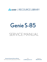
Overview
3
3.1
3.2
1. Electric pump unit
2. Twin hose
3. Hydraulic wrench

12
Description (Cont’d.)
Electric pump unit
The pressure range of the pump unit is 1500 psi - 10,000 psi (100 bar - 700 bar).
1. Hose connection (male coupling) (supply hose) (A)
2. Hose connection (female coupling) (return hose) (B)
3. Oil filling point
4. Oil drain point
5. Oil level sight glass
6. Pressure gauge
7. Pressure control valve
8. Pressure relief valve
9. Remote control
10. Start button
11 . Stop button
12. LED indicator
13. Remote control clamp
3.2.1

13
Description (Cont’d.)
LED indicators (electric pump unit)
115V and 230V pump unit
400V pump unit
3.2.2
Indication Description
Green, continuous The pump unit is ready for use.
Red, flashing (2x)
The direction of rotation is incorrect. Reverse the
polarity of the phase inverter plug.
Red, continuous Error.
Indication Description
Green, continuous The pump unit is ready for use.

14
Pneumatic pump unit
The pressure range of the pump unit is 1500 psi - 10,000 psi (100 bar - 700 bar).
1. Hose connection (male coupling) (supply hose)
2. Hose connection (female coupling) (return hose)
3. Oil filling point
4. Oil drain point
5. Oil level sight glass
6. Pressure gauge
7. Pressure control valve
8. Pressure relief valve
9. Compressed-air inlet
10. Air shutoff valve
11 . Water filter / Air pressure regulator
12. Air lubricator
13. Filter cap
14. Remote control
15. On/off switch
16. Start button
3.2.3
Description (Cont’d.)

15
3.2.4 Hydraulic wrench
1. Hose connection (male coupling) (supply hose)
2. Hose connection (female coupling) (return hose)
3. Square drive for socket connection
4. Drive retainer
5. Disengagement lever
6. Mounting point for safety handle
7. Spline for connection of reaction arm
Description (Cont’d.)

16
Installation (Cont’d.)
Installation
Hydraulic hoses
The working pressure of the hydraulic hoses is 10,000 psi (700 bar). The safety factor of the
hydraulic hoses is 4:1.
Hydraulic hose connections
Use a twin hose to connect the pump unit to the tool. A twin hose consists of two hoses.
The supply hose has two ends with female couplings. The supply hose is connected to the hose
connections with male couplings on the pump unit and the tool. The male coupling on the pump
unit is marked with “A”. The male coupling on the tool is marked with “A”.
The return hose has two ends with male couplings. The return hose is connected to the hose
connections with female couplings on the pump unit and the tool. The female coupling on the pump
unit is marked with “B”. The male coupling on the tool is marked with “R”.
4
4.1
4.1.1
Caution: Do not modify the hydraulic hoses in any way. If you modify the
hydraulic hoses, damage to the equipment can occur.
Note: An odd number of hoses is required to extend the hydraulic hose. You
cannot use an even number of hoses. “PUMP” refers to the electric pump unit.
“TOOL” refers to the tool.

17
Installation (Cont’d.)
Screw-type safety couplings
•
To tighten the couplings, make sure that the system
is depressurized. Push the couplings completely
together to full engagement, and tighten the
locking ring of the female coupling to the male
coupling. If the couplings are not fully tightened,
the tool will not operate.
•
To loosen the couplings, make sure that the system
is depressurized. Loosen the locking ring of the
female coupling from the male coupling and pull
the couplings apart.
Toothed screw-type safety couplings
The coupling is identical to the screw-type safety
couplings, but both coupling are toothed. The male
coupling has a toothed locking ring which is axially
displaceable. The female coupling also has a toothed
ring.
•
To tighten the couplings, make sure that the system
is depressurized. Push the couplings together and
engage the teeth of male coupling and the female
coupling. If the couplings are not fully tightened,
the tool will not operate.
•
To loosen the couplings, make sure that the system
is depressurized. Pull the toothed locking ring
axially and loosen the locking ring.
Quick couplings
•
To tighten the couplings, make sure that the system
is depressurized. Pull back the pullback ring on
the female coupling, push the male coupling
into the female coupling and release the pull-
back ring. Screw the locking ring on the female
coupling against the pullback ring.
•
To loosen the couplings, make sure that the system
is depressurized. Screw the locking ring on the
female coupling from the pullback ring. Pull back
the pull-back ring to remove the male coupling
from the female coupling.
4.1.2 Connecting the hydraulic hoses
Warning:
• Make sure that the system is depressurized.
• Make sure that the hydraulic hoses are securely connected to both the pump
unit and the tool. Make sure that there is no clearance between the male couplings
and the female couplings. If the hydraulic hoses become loose, no hydraulic oil
will flow through the hoses and the tool will not operate.

18
1. If the hose couplings are dirty, clean them
with a lint-free cloth.
2.
Fully tighten the female couplings to the
male couplings.
3. Manually tighten the hose couplings. Do
not use pliers.
Disconnecting the hydraulic hoses
Warning:
• Make sure that the system is depressurized.
1.
Disconnect the return hose from the pump
unit and the tool.
•
If you cannot disconnect the return hose,
press and hold the stop button (B) and
press the start button (A) on the remote
control.
•
If you still cannot disconnect the return
hose, there is residual pressure in the
hose. Press the pressure relief valve (C)
on the pump unit to depressurize the hose.
2.
Disconnect the supply hose from the pump
unit and the tool.
3.
Roll up the hydraulic hoses and connect
the hose couplings to prevent them from
becoming soiled.
Power supply (electric pump units)
There are different types of electric pump units
to operate the tool:
1. 115V pump unit
2. 230V pump unit
3. 400V pump unit
4.1.3
4.2
Installation (Cont’d.)

19
Connecting the power supply (115V)
1. Connect the mains plug to the wall socket.
2.
Use an extension cable that is as short as possible.
3.
Make sure the extension cable is at least 12 awg
and 25 ft. in length*
*refer to extension cord chart on HYTORC.com
Connecting the power supply (230V)
1. Connect the mains plug to the wall socket.
2.
Use an extension cable that is as short as possible.
3.
Make sure the extension cable is at least 12 awg
and 25 ft. in length*
*refer to extension cord chart on HYTORC.com
Connecting the power supply (400V)
1. Connect the mains plug to the wall socket.
2.
If the pump does not start to operate, use a thicker
or shorter extension cable.
3.
Make sure that the direction of rotation is correct.
If the LED indicator on the pump unit lights red,
the direction of rotation is incorrect. Reverse the
polarity of the phase inverter plug.
a) Place a flat-head screwdriver as shown.
b) Turn the insulated plate 180° to reverse the
polarity of the phase inverter plug.
4.2.1
4.2.2
4.2.3
Installation (Cont’d.)

20
Explosion protection (pneumatic pump units)
Several solid metal springs ensure conductivity of the entire system.
Warning:
• Only use ATEX-certified pneumatic pump units, hydraulic hoses and tools in
areas with explosion hazard.
• Let authorized personnel inspect the explosion-proof system on a regular basis.
1. Make sure that all couplings and other connections are tight.
2. Connect a multimeter between the tool and one end of a grounding wire to measure the conductivity.
3. Connect one end of the grounding wire to the pneumatic pump unit.
4. Connect the other end of the grounding wire to an earthing point.
4.3
4.4
Air supply (pneumatic pump units)
1. Connect an air hose to the compressed-air inlet
2.
It is recommended to use a filter regulator
lubricator (FRL):
a) Remove the filter cap (B).
b) Fill the air lubricator (C) halfway with
hydraulic oil. Use only high grade hydraulic
oil (ISO VG 32 or ISO VG 46).
c) Install the filter cap (B).
d) Open the air shutoff valve (D).
e) Turn the air pressure regulator (E) to adjust the
air lubricator (C) to one drop per 60-90
seconds.
f) Close the air shutoff valve (D).
Installation (Cont’d.)
/