Page is loading ...

LASER CLEAN VENTED
MODEL Laser 730/Laser 730AT
CONTENTS
IMPORTANT
READ AND UNDERSTAND INSTRUCTIONS BEFORE INSTALLING OR USING HEATER.
RETAIN INSTRUCTIONS FOR FUTURE REFERENCE. CHECK LOCAL CODES AND ORDINANCES FOR PERMITTED USE.
LASER CLEAN HEATING SYSTEM/VENTED HEATER
INSTALLATION AND OPERATION INSTRUCTIONS
SECTION A:
Specifications
Safety Features
SECTION B:
Safety Tips for Operation
SECTION C:
Fuel Guide
SECTION D:
Operating Controls and Part Names
SECTION E:
Operation
Before Ignition
Operation
Turning Heater Off
SECTION F:
Routine Maintenance
················································ 2
·············································· 3
································ 4
···················································· 5
················· 6
··········································· 9
················································· 10
···································· 15
···································· 16
·············································· 8
·········································· 9
······················ 20
························· 20
········································ 22
·························· 25
··············· 26
······················· 32
························································ 33
SECTION G:
Troubleshooting
SECTION H:
Long Term Storage
SECTION I:
Installation
Tools Needed for Installation
Standard Installation Parts
Accessary Parts
Safety Tips for Installation
Installation of Heater and Flue Pipe
Permanent Wiring Installation
SECTION J:
Fueling
(Type A)
Laser 730&AT_Type A_US.qxd 15.3.18 16:36 ページ 1

SECTION A:
SPECIFICATIONS
Model:
Heater Efficiency:
Heat Rating:
Fuel Consumption:
Fuel System:
Fuel Type:
Dimensions (W × H × D):
(Includes drip tray)
Weight:
Vent Pipe Hole:
Maximum Length of Vent Pipe System:
Electrical Rating:
Typical Room Size (3):
Laser 730/Laser 730AT
92.4% (1)
High - 40,000 BTU/h
Med - 27,000 BTU/h
Low - 15,000 BTU/h
High - 0.301 gal/h (1.14 L/h)
Med - 0.203 gal/h (0.768 L/h)
Low - 0.113 gal/h (0.428 L/h)
External tank (2)
1-K kerosene (ASTM D3699)
Low Sulfur No.1 Fuel (ASTM D396 S500)
Ultra Low Sulfur Diesel Fuel (ULSD) or
Ultra Low Sulfur Heating Oil (ULSHO) (ASTM D975 S15)
30” × 27-1/2” × 16-3/4” (760 × 700 × 427 mm)
75 lbs. (34 kg) Empty
2-3/4” - 3” (7.0 - 7.5 cm) diameter
10 ft. (3 m), 3 bends or less
120 Volts AC, 60 Hz
Preheat
-
260W
Burning
-
50W
1670 square feet (0˚F)
2000 square feet (20˚F)
(1)
(2)
(3)
Heat and vaporized water are produced by the combustion process of this heater. This rating does not take
into account heat loss due to condensation of water vapor.
External tank to be purchased from local suppliers.
0˚ F Heat Load = 24 BTU/ft2/hr
20˚ F Heat Load = 20 BTU/ft2/hr
Room size for which this heater is suitable will vary depending on outside temperature, house
insulation, window size, and other factors.
2
Laser 730&AT_Type A_US.qxd 15.3.18 16:36 ページ 2

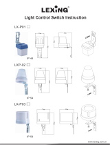
Heat chamber
Adjustable leg Blower motor
Peep hole
Burner ring
Flame sensor
Igniter
Burner Integral fuel strainer (inside)
Heat exchanger
Overheat protectorCirculation fan
Fuel pipe
Fuel pump
Fuel sump
Red reset button
Drip tray
Heat shield plate
Flame Sensor
Heater will automatically stop all operations if ignition fails or if flame fails during combustion, in order to
prevent fuel overflow. Error code will be displayed on the digital indicator.
Fuel Strainer
Special strainer catches dirt or impurities present in the fuel before it is sent to the burner.
Overheat Protector
Automatically stops all operations if heater inside cabinet reaches abnormally high temperature due to motor
malfunction or abnormal combustion, in order to prevent fire.
Power Failure Recovery System
If power fails during heater operation, heater will automatically reignite and maintain the normal selected
temperature, when power resumes.
Fully Vented System
Flue pipe system uses outside air for combustion and vents all combustion products to the outdoors.
1.
2.
3.
4.
5.
SAFETY FEATURES
Your Laser 730/Laser 730AT is equipped with the following safety features. Please familiarize yourself with
these features. When your heater is extinguished due to a safety mechanism, be sure to identify and correct
the problem.
3
Laser 730&AT_Type A_US.qxd 15.3.18 16:36 ページ 3

CAUTION:
0204060
-20 A
B
Room Temperature (˚F)
Outside Temperature (˚F)
-25
-30
-35
-40
-45
SECTION B:
SAFETY TIPS FOR OPERATION
If outside temperature -20°F
than room temperature has to be 0°F or above
If outside temperature -45°F
than room temperature has to be 60°F or above
Point A:
Point B:
Heater and vent pipe system must be properly installed before operation.
Please follow instructions under “Installation”, Section I.
Never use any fuel other than clear or red colored kerosene (ASTM D3699 1-K
Kerosene, ASTM D396 Low Sulfur No.1 Fuel Oil, ASTM D975 Ultra Low Sulfur
Diesel (ULSD), or Ultra Low Sulfur Heating Oil (ULSHO)). NEVER USE
GASOLINE. Use of gasoline can lead to uncontrollable flames, resulting in
destructive fire.
1.
Due to high surface temperatures, keep heater away from children, furniture and
clothing while in operation (See Page 26).
2.
To prevent abnormal operation and prolong heater life, be sure to perform
routine maintenance (See Pages 16).
3.
Never store or transport kerosene in other than a metal or plastic container that
is clearly marked, “KEROSENE”, “No.1 FUEL OIL”, “ULTRA LOW SULFUR
DIESEL”, or “ULTRA LOW SULFUR HEATING OIL”. Never store fuel in the living
space.
4.
Operating Temperature Range
Use heater within the range of temperatures
indicated in the right figure.
5.
Operating Range
RIGHT
KEROSENEKEROSENE
WRONG
GAS
Kero-
sene
Danger
4
Laser 730&AT_Type A_US.qxd 15.3.18 16:36 ページ 4

KEROSENE
SECTION C:
FUEL GUIDE
Clean and high-quality ASTM D3699 1-K Kerosene, ASTM D396 Low
Sulfur No.1 Fuel Oil, ASTM D975 Ultra Low Sulfur Diesel (ULSD), or
Ultra Low Sulfur Heating Oil (ULSHO).
Fuel free of contaminants, water or cloudiness.
Gasoline, alcohol, white gas, camp stove fuel or additives.
Yellow or sour-smelling fuel.
Store in a clean container, non-red in color, clearly marked KEROSENE,
No.1 FUEL OIL, ULTRA LOW SULFUR DIESEL, or ULTRA LOW
SULFUR HEATING OIL.
Store away from direct sunlight, heat sources or extreme tempera-
ture changes.
In a glass container, or one that has been used for other fuels.
For longer than six months. Begin each heating season with fresh
fuel; discard at the end of season.
In the living space.
• Excess tar deposits on burner and flue pipe
• Incomplete combustion
• Reduced heater life
What to Buy . . .
ALWAYS :
ALWAYS :
NEVER :
NEVER :
How to Store It . . .
ALWAYS :
ALWAYS :
NEVER :
NEVER :
NEVER :
Why It is Important . . .
Good, clean fuel is essential for safe and efficient heater operation. Poor quality or
contaminated fuel can cause:
Use of a highly volatile flammable fuel such as gasoline can produce
uncontrollable flames, creating a severe fire hazard.
Note: The fluidity of Ultra Low Sulfur Diesel and Ultra Low Sulfur Heating Oil becomes
worse at temperatures of 21˚F (-6˚C) and below and can “gel”. This condition may
cause ignition failure. To prevent congealing it is recommended to use an additive
with the fuel. Check with a fuel supply company for the proper additive and mix.
GAS
The Toyostove Laser 730/Laser 730AT is designed for use with ASTM D3699 1-K kerosene, ASTM D396 Low Sulfur
No.1 Fuel Oil, ASTM D975 Ultra Low Sulfur Diesel (ULSD), or Ultra Low Sulfur Heating Oil (ULSHO). Use of low-
quality fuel will cause burner performance to drop, leading to abnormal combustion and reduced heater life.
Purchase only ASTM D3699 1-K kerosene or ASTM D396 Low Sulfur No.1 Fuel Oil, ASTM D975 Ultra Low Sulfur Diesel
(ULSD), or Ultra Low Sulfur Heating Oil (ULSHO) in non-red cans reserved exclusively for kerosene and marked
accordingly with the word “KEROSENE”, “No.1 FUEL OIL”, “ULTRA LOW SULFUR DIESEL”, “ULTRA LOW SULFUR
HEATING OIL”. Always store your fuel in a separate area from where you store gasoline for your power equipment to
avoid accidental use of gasoline in your heater.
5
Laser 730&AT_Type A_US.qxd 15.3.18 16:36 ページ 5

SET ROOM
MIN.
HOUR AUTO
ON / OFF
SETTIMER
CHILD LOCK
˚F / ˚C
POWER SAVER
CLEAR
DAY
SELECT
Programmable System
Before using the heater, familiarize yourself with the following operating controls and part names.
SECTION D:
OPERATING CONTROLS AND PART NAMES
5. POWER SAVER/DAY SELECT button
3. TIMER button
14. AM/PM indicator
9. AUTO indicator
10. TIMER indicator
11. POWER SAVER indicator
12. CHILD LOCK indicator
Fuel strainer
(inside)
4. TEMP/TIMER/CLOCK/DAY set
16. DAY of the week indicator
7. ˚F/˚C switch
Make a note of your heater’s serial number,
located on the outside cabinet surface.
Your heater’s serial number:
SERIAL NO.
6. CHILD LOCK/CLEAR button
2. AUTO button
1. ON/OFF button
8. ON lamp
13. BURNING MODE indicator
15. ˚F/˚C indicator
17. Circulation fan
Circulation fan motor
Fan cover
Drip tray
Front panel
Louvers
19. Power
supply cord
20.
Plumb bob
Red reset button
Pipe stopper
Control panel
18. Room tempe-
rature sensor
Exhaust outlet
Air inlet
6
Laser 730&AT_Type A_US.qxd 15.3.18 16:36 ページ 6

1. ON/OFF button:
2. AUTO button:
3. TIMER button:
4. TEMP/TIMER/CLOCK/DAY set:
5. POWER SAVER/DAY SELECT button:
6. CHILD LOCK/CLEAR button:
7. ˚F/˚C switch:
8. ON lamp:
9. AUTO indicator:
10. TIMER indicator:
11. POWER SAVER indicator:
12. CHILD LOCK indicator:
13. BURNING MODE indicator:
14. AM/PM indicator:
15. ˚F/˚C indicator:
16. Day of the week indicator:
17. Circulation fan:
18. Room temperature sensor:
19. Power supply cord:
20. Plumb bob:
Main button switch turns heater on and off. When
switched on, heater begins operation and
combustion starts after preheat period.
The button turns weekly timer operation modes on and
off which have been programmed into weekly timer.
The button turns weekly timer set mode on and off.
TEMP/TIMER/CLOCK/DAY set modes can be set by
pressing the ▲MIN. or ▼HOUR buttons.
The button turns POWER SAVER operation mode on
and off. When setting weekly timer, the button is used
to select a day of the week.
The button turns CHILD LOCK operation mode on
and off. When setting weekly timer, the CLEAR button
is used.
C/F toggle switch.
Lit – Heater is in operation.
Flashing – Pre-heating and pre-purging.
Lit – Weekly timer operation is in use.
Lit – Heater operating in weekly timer set mode.
Lit – Heater operation in POWER SAVER mode.
Lit – Heater operation in CHILD LOCK mode.
Lit – Heater operation at high, medium or low
combustion.
Lit – Digital indicator shows current time.
Flashing – Current time can be changed.
Lit – Digital indicator shows current temp.
Flashing – Current temp can be changed.
Lit – Digital Indicator shows current day or timer day.
Three speed motor supplies high-capacity warm air
flow during high combustion for heating room up
quickly, and low or medium-capacity warm air flow
during low or medium combustion for maintaining
comfortable room temperature.
Constantly senses room temperature and supplies
information to heater so that desired room
temperature can be maintained.
For use in 120V, AC electrical outlet.
Allows user to check if heater is positioned evenly.
7
Laser 730&AT_Type A_US.qxd 15.3.18 16:36 ページ 7

REF # PART # PART NAME
REF # PART # PART NAME REF # PART # PART NAME
1
2
3
4
5
6
7
8
9
10
11
12
13
14
15
16
17
18
19
20
21
22
23
24
25
26
27
28
29
30
31
32
33
34
35
36
37
38
39
40
41
42
43
44
45
46
47
48
49
50
50
51
52
53
54
55
56
57
58
59
60
61
62
63
64
65
66
67
68
69
70
71
72
73
74
75
76
77
78
79
80
81
82
83
84
85
86
87
88
89
20470646
20479145
20475804
20479104
20450007
20474970
20478129
20479129
20470660
20479160
20470663
20470763
20470664
20479164
20475172
20478644
20475808
20470642
20478643
20478026
20478383
20470218
17187582
20479521
20474920
20470611
20475194
20475850
20475831
20475881
20474992
20475893
20470638
20470648
20478871
20475883
20475875
20475878
20475877
20470234
20470619
20470641
20478550
20475551
20475552
20470612
20470678
20470679
20470206
20470676
20470776
20474977
20474975
20477414
20474984
20470651
20470652
20470669
20478373
20479891
20474925
20475535
20478188
20479885
20455862
20470756
20470254
20474039
20474057
20470353
20470355
20450220
20478090
20476150
20474985
20475171
20474983
20478613
20478366
20478683
20474163
20470675
20470273
20470666
20475554
20474053
20479957
20470695
20470699
20470799
Front panel assembly
Front panel assembly (Laser 730AT)
Carrying handle
Carrying handle (Laser 730AT)
Plumb bob
Adjustable leg
Drip tray
Drip tray (Laser 730AT)
Top plate
Top plate (Laser 730AT)
Right side panel
Right side panel (Laser 730AT)
Left side panel
Left side panel (Laser 730AT)
Fan cover
Heat exchanger
Heat chamber assembly
Burner assembly
Burner ring
Fuel nozzle
Fuel nozzle gasket
Igniter
Igniter gasket
Igniter guide gasket
Igniter cover
Primary flame rod
Burner gasket
Burner insulating pad
Peep window
Peep window gasket
Joint packing
Heat chamber gasket
Blower motor assembly
Blower motor assembly with case
Blower motor exhaust fan
Blower motor intake fan
Blower motor case gasket
Rubber mat
O-ring (ø75)
Fuel sump
Fuel pump
Fuel pipe assembly
Fuel inlet strainer
Drain screw with O-ring
Strainer gasket
Main circuit board
Fuse 1 (5A)
Fuse 2 (10A)
High limit switch
Operation panel
Operation panel (Laser 730AT)
Hose band
L-shaped hose
PCB support
Bent joint (L)
Inlet hose
Leveler fuel pipe
Circulation fan motor
Thermistor
Flue pipe
Oil catch
Power supply cord
Screw 1X
Outside nozzle gasket
Screw S2
Screw 4D (Laser 730AT)
Screw 4J
Insulator A
Flange nut
Screw 4P
Screw 4Q
Screw 4I
Screw 1T
Washer E
Screw 4G
Circulation fan
Outlet adapter
Burner mat
Air damper (ø25)
Draft tube
Screw I
Ribbon cable
Burner thermistor
Screw 4C
Screw 1Q
Screw F
Nut J
Instruction manual
Carton
Carton (Laser 730AT)
3,4
13,14
66
66
9,10
a
64,65
58
67
15
83
75
66
66 70
57
61
64,65
3,4
11,12
5
71 60
49
50
81
55
53
a
74
59
7,8
64,65
1,2
66
85
56
69
41 40
42
36
34
73
35
86
37
84
76
66
19
16
39
72
32
62
66
31
17
29
30
80
66
66
38
33
18
68
28
27
77
79
26
24
23
66
6
78
22
25
66
66
21
20 63
66
82
66
45
44
43
48
46
47
52 51
54
51 52
8
Laser 730&AT_Type A_US.qxd 15.3.18 16:36 ページ 8

SET ROOM
MIN.
HOUR AUTO
ON / OFF
SETTIMER
CHILD LOCK
˚F / ˚C
POWER SAVER
CLEAR
DAY
SELECT
Reset Button
BEFORE IGNITION
1. Open the Valve(s)
Open the valve(s) of the external fuel tank.
2. Start the Fuel flow
If using heater for the first time, press the red reset button in order to send fuel to
the fuel sump and release.
Note: Make sure there is no fuel leakage from the fuel line or joints.
Also make sure fuel tank is not too high. See installation instructions.
3. Plug in the Heater
Plug heater into a 120V AC electrical outlet. On digital indicator pre-set “Two
Dashes” will be showing.
Note: Do not connect to an outlet shared with other appliances.
4. Set Clock
Important: Clock on the heater must always be set to current time and day.
Note: “HOUR” or “MIN” button will change the time every one (1) unit. Holding the button
continuously will cause the time to change rapidly.
Note: In the event of a power failure (more than approx. 30 min.) all clock and day may be
cancelled.
5. Setting of the Time and a Day of the Week.
1) Current time is not set yet. (All signs light.)
Press the “▲MIN.” button or “▼HOUR” button while in not operation. (Power switch is off.)
AM 12:00 is indicated on the display. (All signs except the colon are blinking.)
2) Setting of the current time
Press the “▲MIN.” button to set minutes and press the “▼HOUR” button to set hours.
When pressing the “▼HOUR” button, the sign will change as follows.
“AM 12:00” ➞ “AM 1:00” ➞ ··· ➞ “AM 11:00” ➞ “PM 12:00” ➞ “PM 1:00” ➞ ··· “PM 11:00” ➞ “AM 12:00” ➞ ···
When pressing the “▲MIN.” button, the sign will change as follows.
“AM 12:00” ➞ “AM 12:01” ➞ ··· ➞ “AM 12:59” ➞ “AM 12:00” ➞ ···
Press the “SET” button to complete the set of the current time.
SECTION E:
OPERATION
Programmable System
9
Laser 730&AT_Type A_US.qxd 15.3.18 16:36 ページ 9

3) Setting of a day of the week
“dAy” sign is shown on the display and all of days of the week will blink.
Press the “▲MIN.” button or the “▼HOUR” button to set a day of the week. A day of the week will blink. (Initial
setting is “SUN”.) The other days of the week will go off. Select a day of the week by using the “▲MIN.” or the
“▼HOUR” button. When pressing the “▲MIN.” button, the sign will change as follows.
“SUN” ➞ “MON” ➞ “TUE” ➞ “WED” ➞ “THU” ➞ “FRI” ➞ “SAT”
When pressing the “▲MIN.” button at the position of “SAT”, you can hear a beep sound and “SAT” is not
changed any more. When pressing the “▼HOUR” button, the sign will change as follows.
“SAT” ➞ “FRI” ➞ “THU” ➞ “WED” ➞ “TUE” ➞ “MON” ➞ “SUN”
When pressing the “▼HOUR” button at the position of “SUN”, you can hear a beep sound and “SUN” is not
changed any more.
Press the “SET” button to complete the setting of the days of the week. The current time and a day of the week
will show on the display.
Note: If the ON/OFF switch is pressed during setting of the current time and a day of the week after setting the
time and a day of the week, the set mode of the current time will terminate and the operation will start. If a
day of the week is set, the time is fixed. If a day of the week is not set, the contents of the setting are
deleted.
OPERATION
MANUAL OPERATION
Operation of the heater is under the direct control of the user. Heat output will, however, be automatically
adjusted in accordance with the room temperature registered by the temperature sensor.
1. Turn Heater ON
A. Press ON/OFF button to “ON” position. The current room temperature and the set temperature will be
shown on the button digital indicator. ON lamp will start to flash and then blower motor and ignition will
start. This lamp will continue to flash during the preheating time.
B. After approx. 3 – 9 minutes ignition will take place. *After ignition, ON lamp will change from flashing to
continuous. Circulation fan will turn on after approx. 2 minutes.
Note: *Pre -heating depends on the room temperature.
Room temperature: below 34˚F Approx. 9 minutes
34˚F - 61˚F " 6 minutes
over 61˚F " 3 minutes
SET ROOM
MIN.
HOUR AUTO
ON / OFF
SETTIMER
CHILD LOCK
˚F / ˚C
POWER SAVER
CLEAR
DAY
SELECT
Programmable System
10
Laser 730&AT_Type A_US.qxd 15.3.18 16:36 ページ 10

2. Adjusting Room Temperature
A. Press “HOUR” or “MIN.” button. ˚F or ˚C will start to flash.
Note: “HOUR” or “MIN.” button will change the temperature in increment of 2˚F (1˚C).
B. Press “MIN.” for up and “HOUR” for down. Room temperature can be set from 50˚F (10˚C) to 90°F (32˚C).
(Initial setting : 56˚F (13˚C))
C. When room temperature reaches the selected setting, heater will automatically shift
to “MED” or “LOW” burning mode to maintain the desired temperature.
When room temperature exceeds the selected setting by approx. 4˚F (2˚C), the
heater will automatically shut off. As room temperature drops, the heater will
automatically re-start to maintain the desired temperature.
POWER SAVER OPERATION
The Power Saver mode reduces the frequency of ignition actions, to save electric
consumption.
Press the POWER SAVER (DAY SELECT) button “ON” while in operation to start the
operation of the “POWER SAVER”. “POWER SAVER” sign will be shown on the digital
indicator.
When the room temperature exceeds the selected setting by approximately 10˚F (6˚C), the
heater will automatically shut off. As the room temperature becomes lower than the
selected setting, the heater will automatically re-start to maintain the desired temperature.
Approx. +4˚F
Approx. +1˚F
SET
TEMP.
High Medium Low Off Re-lgnition
SET ROOM
MIN.
HOUR AUTO
ON / OFF
SETTIMER
CHILD LOCK
˚F / ˚C
POWER SAVER
CLEAR
DAY
SELECT
SET ROOM
MIN.
HOUR AUTO
ON / OFF
SETTIMER
CHILD LOCK
˚F / ˚C
POWER SAVER
CLEAR
DAY
SELECT
Programmable System
Programmable System
11
Laser 730&AT_Type A_US.qxd 15.3.18 16:36 ページ 11

CHILD LOCK OPERATION
Press the CHILD LOCK (CLEAR) button for more than 3 seconds to set the child
lock while in operation or not in operation. “CHILD LOCK” sign will be shown on
the digital indicator.
If the ON/OFF Switch is pressed while the Child Lock is on while in not operation,
you can hear the beep sound, but the unit does not start. If the ON/OFF Switch is
pressed while the Child Lock is on while in operation, the heater will automatically
shut down with a beeping sound. “CHILD LOCK” on the digital indicator will flash
and “OFF” will be shown on the digital indicator.
To release the warning, press the CHILD LOCK (CLEAR) button for more than 3
seconds.
Approx. +10˚F
Approx. +1˚F
SET
TEMP.
High Medium Low Off Re-lgnition
SET ROOM
MIN.
HOUR AUTO
ON / OFF
SETTIMER
CHILD LOCK
˚F / ˚C
POWER SAVER
CLEAR
DAY
SELECT
SET ROOM
MIN.
HOUR AUTO
ON / OFF
SETTIMER
CHILD LOCK
˚F / ˚C
POWER SAVER
CLEAR
DAY
SELECT
Programmable System
Programmable System
12
Laser 730&AT_Type A_US.qxd 15.3.18 16:36 ページ 12

WEEKLY TIMER OPERATION
1. Set the Weekly Timer
Note: The following programs are set at the factory in advance.
After setting the current time and a day of the week, press the “TIMER” button to enter the weekly timer setting
mode. The “TIMER” is shown on the display. When the “TIMER” button is pressed during setting of the weekly
timer, the “TIMER” sign disappeared and the current clock time and a day of the week are shown on the display.
Note: You cannot enter the weekly timer setting mode, while in operation and AUTO operation mode, on.
1) Select the program number
Press the “▲MIN.” button or the “▼HOUR” button to select the program number.
The number of program numbers is 30. The non-set program number will flash on the display. In case of the first
setting of the weekly timer, “P01” is shown on the display and will blink. In case that the program is already set,
the next number of the biggest setting program number is shown on the display. If the program is set until “P30”,
“P30” is shown on the display and will blink. Even though all program number are set to “P30”, if there is any
non-set program number, the smallest non-set program number is shown on the display.
When pressing the “▲MIN.” button, the sign will change as follows.
“P01” ➞ “P02” ➞ ··· ➞ “P29” ➞ “P30”
When pressing the “▲MIN.” button at the position of “P30”, you can hear a beep sound and “P01” is not
changed any more.
When pressing the “▼HOUR” button, the sign will change as follows.
“P30” ➞ “P29” ➞ ··· ➞ “P02” ➞ “P01”
When pressig the “▼HOUR” button at the position of “P01”, you can hear a beep sound and “P01” is not
changed any more.
Example:
In case that “P01” and “P02” programs are set and “P03” is not set, the display shows as follows.
“P01” – solid ⇔ “P02” – solid ⇔ “P03” – flashing 3
In case that “P01” and “P04” programs are set and “P02” and “P03” are not set, the display is indicated as
follows.
“P01” – solid ⇔ “P02” – flashing 3 ⇔ “P03” – flashing 3 ⇔ “P04” – solid ⇔ “P05” – flashing 3
When a non-set program number is shown on the display, all of a day of the week will blink.
Press the “SET” button to move to the next step (Set the timer).
The program number memory is cleared by holding the “CLEAR” button continuously for 3 seconds.
Program #
P01
P02
P03
P04
P05
P06
P07
P08
Clock Time
AM 6:00
AM 8:30
PM 5:00
PM 11:00
AM 7:00
AM 10:00
PM 4:00
PM 11:00
Temp.
68˚F (20˚C)
62˚F (16˚C)
68˚F (20˚C)
62˚F (16˚C)
68˚F (20˚C)
62˚F (16˚C)
68˚F (20˚C)
62˚F (16˚C)
Day
“MON” “TUE” “WED” “THU” “FRI”
“MON” “TUE” “WED” “THU” “FRI”
“MON” “TUE” “WED” “THU” “FRI”
“MON” “TUE” “WED” “THU” “FRI”
“SUN” “SAT”
“SUN” “SAT”
“SUN” “SAT”
“SUN” “SAT”
13
Laser 730&AT_Type A_US.qxd 15.3.18 16:36 ページ 13

2) Set the timer
The timer is shown on the display. (In the case that the timer time is not set, dashes are shown on the display.)
Press the “▲MIN.” button or the “▼HOUR” button to set timer time. “AM 12:00” will be shown on the display.
(The all signs except the colon will blink.)
When pressing the “▼HOUR” button, the sign will change as follows.
“AM 12:00” ➞ “AM 1:00” ➞ ··· ➞ “AM11:00” ➞ “PM 12:00” ➞ “PM 1:00” ➞ ··· ➞ “PM 11:00” ➞ AM 12:00” ➞ ···
When pressing the “▲MIN.” button, the sign will change as follows.
“AM 12:00” ➞ “AM 12:10” ➞ “AM 12:20” ➞ “AM 12:30” ➞ “AM 12:40” ➞ “AM 12:50” ➞ “AM 12:00” ➞ ···
Press the “SET” button to complete the setting of the timer time and to move to the next step (Set the
temperature of the Program Number).
In case that the “SET” button is pressed when showing the bars sign on the display, you can hear the beep
sound and cannot move to the next step.
3) Set the temperature of the Program Number
The set temperature “70” will be shown on the display and it will blink.
Press the “▲MIN.” button or the “▼HOUR” button to set the temperature of the program. The “▲MIN.” button or
the “▼HOUR” button will change temperature every 2˚F (1˚C).
Press the “SET” button to complete the set the temperature of the program and move to the next step (Set a
day/s of the week for the Program Number).
4) Set a day/s of the week for the Program Numver
The “dAy” sign will be shown on the display and the “SUN” will blink. Press the “▲MIN.” button or the “▼HOUR”
button to set a day of the week, When pressing the “▲MIN.” button, that day is turned on. The day of the week
will light and will more to the next day automatically. When pressing the “▼HOUR” button, that day is turned off.
The day of the week will go off and will more to the next day automatically. When pressing the “DAY SELECT”
button, the display will show the next day of the week without setting. The sign of a day of the week will change
as follows.
“SUN” ➞ “MON” ➞ “TUE” ➞ “WED” ➞ “THU” ➞ “FRI” ➞ “SAT” ➞ “SUN” ➞ ···
Press the “SET” button to complete the set of a day of the week of the program and it will go back to the select
of the program number. In case that a day of the week is not set, when pressing the “SET” button, you can hear a
beep sound and cannot move to the next step.
14
Laser 730&AT_Type A_US.qxd 15.3.18 16:36 ページ 14

2. Activate Weekly Timer Operation
During operation (in ON position), press the “AUTO” button to turn on the weekly timer operation mode. However, if no
program are set, you will hear the beep sound and cannot turn on the weekly timer operation mode. Press the “▲MIN.”
button or the “▼HOUR” button to change the set temperature. However, if the next program starts, the temperature will
be changed to the temperature of the next program.
During operation, press the “TIMER” button to enter the weekly timer set mode (Select the program number). If
the “TIMER” button is pressed during the setting of the weekly timer set mode, the weekly timer set mode is
turned off. Change of setting is applied as soon as the AUTO operation is turned on.
MANUAL COMBUSTION
Important: This feature is for testing purpose only!
This heater can also be kept burning at desired combustion mode (High, Medium or low) manually, regardless of
room temperature.
1. Press the “▲MIN.” button and “▼HOUR” button at the same time for more than three (3) seconds when ON /
OFF button is “ON”.
2. P1, P2 or P3 will be displayed on the Digital Indicator;
P1 = Low mode
P2 = Medium mode
P3 = High mode
Then select desired combustion mode by pressing “▲MIN.” or “▼HOUR” button. “▲MIN.” button changes
combustion mode to higher, “▼HOUR” button changes combustion mode to lower.
3. To clear, press the “▲MIN.” button and “▼HOUR” button at the same time for more than (3) seconds until
normal temperature display returns.
AUTOMATIC CLEANING MODE
When the heater has been burning continuously for two hours at its highest setting, the
burner will automatically start an auto clean procedure. The display will show the auto
cleaning code cl:05 running back to cl:01. The procedure takes 5 minutes to clean the
burner automatically, while the heater will burn at its lowest setting. When the burner is
clean again, the heater will automatically switch back to the highest setting again.
TURNING HEATER OFF
Press ON/OFF button to “OFF” position. ON lamp will flash and will go out. Circulation fan
and blower motor continue to run for approx. three (3) minutes to cool down the heater.
Make sure ON lamp goes out when the fan stops.
SET ROOM
MIN.
HOUR AUTO
ON / OFF
SETTIMER
CHILD LOCK
˚F / ˚C
POWER SAVER
CLEAR
DAY
SELECT
Programmable System
15
Laser 730&AT_Type A_US.qxd 15.3.18 16:36 ページ 15

Check
Check
FOR OPTIMUM HEATER PERFORMANCE, THE PARTS SHOWN BELOW SHOULD BE CLEANED REGULARLY:
CAUTION:Be sure to turn off and unplug heater before performing any checks or cleaning.
CAUTION:Allow heater to cool completely before cleaning or maintenance.
SECTION F:
ROUTINE MAINTENANCE
1. Clean Louvers (ONCE A MONTH)
Dust and stains should be wiped off louvers with a damp cloth.
2. Clean Circulation Fan Cover (ONCE A MONTH)
Remove dust and/or pet hair from the cover on the back of the heater.
Use a vacuum to remore any dust or pet hair.
3. Check for Fuel Leaks (REGULARLY)
Make it a habit to check for any signs of fuel leakage along the fuel line and at all
joints. Fuel leaks may lead to risk of fire, and should be corrected immediately.
4. Check Flue Pipe Area (ONCE A MONTH)
Check the flue pipe joint to make sure connection is firm. Use a vacuum
cleaner to remove any dust or pet hair.
Louvers
Fan cover
Fuel strainer
(Inside)
16
Laser 730&AT_Type A_US.qxd 15.3.18 16:36 ページ 16

5. Clean Fuel Strainer (ONCE A SEASON)
The strainer of the fuel sump should be cleaned once a season and before
starting the heater at the beginning of each season.
(a) Close the valve closest to the heater.
(b) To catch the fuel which will drain out, set the Oil catch below the Strainer
cover, with a small container under it.
(c) Loosen the two screws from the Strainer cover and remove.
(d) Remove the strainer and wash with kerosene or fuel oil.
(e) Return the strainer to its original position. Replace strainer cover and screw
to secure.
(f) Wipe away any spilled fuel.
(g) Open the valve in the fuel line. Check for fuel leakage.
Note: At the end of each season unscrew the drain screw to remove all the remaining fuel from the fuel
sump. Be sure to follow procedure A and B listed above and replance Drain screw.
6. Recommended Periodic Maintenance
As a state-of-the-art furnace, your heater requires periodic inspection and service by an authorized technician
to insure optimum, trouble free performance. This inspection should include: a combustion check; flue pipe
check; burner assembly check; cleaning all necessary parts and replacing gaskets as needed. Please ask
your authorized Toyostove dealer for details and scheduling. When using Ultra Low Sulfur Diesel (ULSD) or
Ultra Low Sulfur Heating Oil the heater should be serviced at least every two years because the distillation of
ULSHO is heavier than 1-K Kerosene and No. 1 Fuel Oil. When using 1-K Kerosene or Low Sulfur No. 1 Fuel
Oil your heater can be serviced less frequently.
AUTOMATIC IGNITER CLEANING SYSTEM
When the heater is on and clock is set (see “set Clock” on page 9), it will automatically stop and clean the igniter
every day at 2:00 AM and will display “CL” on the digital indicator. After the cleaning mode is finished the heater will
automatically re-ignite and continue to burn again.
The igniter cleaning mode helps prolong the igniter life.
MANUAL IGNITER CLEANING SYSTEM
Heater will clean igniter for ten (10) minutes manually.
1. When ON/OFF switch is “OFF”, press the “SET” button and “CLEAR” button at the same time for more than
three (3) seconds.
2. Display will appear “CL:10” on Digital Indicator. Cleaning will begin and end without any additional input.
Note: Cleaning igniter is important to prolong igniter life. It is recommended that the igniter be cleaned once a
month if the time is not set.
Drain
Screw
Oil catch
Fuel
Strainer
Strainer
gasket
Strainer
cover
17
Laser 730&AT_Type A_US.qxd 15.3.18 16:36 ページ 17

The following symptoms are normal during operation of the heater.
White smoke or smell at initial use after
purchase.
Flames flashing for a few minutes after
ignition.
Occasionally makes “cracking” noise when
heater is ignited or extinguished.
Part of the heat chamber or the heat
exchanger is heated to a cherry red color.
Warm air will not blow as soon as ignited.
Audible chugging sound from fuel pump
when started first time or after running out
of fuel.
“Ticking” noise.
Machine oil or dust burns off of the surfaces the
surfaces of the burner or heat exchanger.
The burner is cold and igniter is kept running
for a while after ignition.
Expansion and shrinkage of metal parts when
they are heated or cooled.
To prevent uncomfortable cool air from
coming out at the beginning, the circulation fan
start up is delayed.
Air is in the pump. However, noise should
stop within 1 minute.*
Noise of fuel pump in operation.
Normal.
Normal.
Occasional yellow flickering in blue flame. Normal.
When heater is started
or extinguished.
When heater is
in operation.
CONDITION REASON
SECTION G:
TROUBLESHOOTING
NOTE BEFORE REQUESTING FOR REPAIR AND SERVICES
ERROR CODE
E– 0
E– 23
E– 6
E– 2
E– 2 / E– 6
E– 8
E– 12
E– 13
E– 13
E– 22
CAUSE
Power failure (low voltage, unstable
frequency)
Primary flame (Flame sensor) is
malfunction and/or dirty
Fuel line malfunction
Out of fuel / no flame
Flue pipe blockage or leak
Blower motor malfunction
High limit switch activated
Burner thermistor failure
Flue pipe blockage or leak
Ignition failure three times
SOLUTION
Check power source.
Consult your dealer for cleaning and in
spection.
Consult your dealer.
Check fuel gauge on fuel tank; refuel.
Consult your dealer. / Check flue pipe.
Consult your dealer.
Clean circulation fan filter and remove any
obstructions, allow your heater to cool
completely and re-ignite.
Consult your dealer.
Check flue pipe. / Consult your dealer.
Consult your dealer.
*If sound from fuel pump does not decrease and heater shuts off, check:
1. Push red reset button on fuel sump once. DO NOT hold down.
2. Insure that all valves are open and filter is clear.
3. Insure external fuel tank has fuel and filters are clean.
Should problems arise during operation or ignition, use this chart to determine the cause and the proper steps to
take. Be sure to unplug heater and allow to cool completely before taking corrective measures.
In the event that heater should extinguish itself, without any action or your part, you should look to the digital
indicator for any of the following error codes.
18
Laser 730&AT_Type A_US.qxd 15.3.18 16:36 ページ 18

At the end of each heating season, or when you do not plan to use your heater for an extended period, the
following procedures are recommended.
1. As the end of the season approaches, calculate your fuel purchases so that you can use up all the fuel you
have on hand. When fuel is stored for over six months, its quality may deteriorate. The use of such fuel will
have an unfavorable effect on heater operation.
2. If your heater needs any service or repair, now is the time to call your dealer and get it done before storage.
That way your heater will be ready for immediate use when the next heating season begins.
3. If you plan to store your heater in place,
(a) Disconnect power supply.
(b) Close the main tank valve.
(c) Remove all fuel from the fuel sump and clean the fuel strainer.
(d) Wipe off any stains or dust on heater with a damp cloth, then wipe once
again using a dry cloth.
4. To store heater in another location,
(a) Disconnect heater.
(b) Close the main tank valve.
(c) Remove all fuel from the fuel sump and clean the fuel strainer.
(d) Disconnect fuel line and flue pipe from the heater.
Note: Fuel remaining in the fuel line may flow out when fuel line is disconnected. Have a container ready
to catch drainage.
(e) Remove any soot accumulated in the flue pipe using a brush and/or vacuum cleaner.
(f) Wipe off any stains or dust on heater with a damp cloth, then wipe once again using a dry cloth.
(g) Put the heater in the original shipping box, and store in a dry place. If original shipping box is not
available, cover the heater completely with a large plastic bag to protect from dust during storage.
(h) Plug exhaust and air intake openings of the flue pipe by using optional caps.
(Part #20479845 and #20474949)
TRANSPORTATION
Take the following measures to avoid fuel leakage during the transportation of the heater.
- Always move the heater in an upright position.
- Always drain fuel from the fuel sump before transportation.
SECTION H:
LONG TERM STORAGE
Dealer
19
Laser 730&AT_Type A_US.qxd 15.3.18 16:36 ページ 19

Pipe Holder (1) (PART #20474963)
Wall Brackets (2 sets) (PART #20474962)
Pipe Stopper (1) (PART #20474964)
Drip Tray (1) (PART #20478129 for Laser 730)
(PART #20479129 for Laser 730AT)
SECTION I:
INSTALLATION
TOOLS NEEDED FOR INSTALLATION
STANDARD INSTALLATION PARTS
The following standard installation parts are enclosed with heater. For alternate installation methods, you may need
to purchase additional accessories which are available from your TOYOSTOVE dealer. See “Accessory Parts”,
page 22.
Tool Use
Phillips Head Screwdriver Installation of flue pipe, etc.
Electric Drill Drilling hole in wall for flue pipe
Hole Saw, 2-3/4 to 3” diameter Making hole in wall for flue pipe
20
Laser 730&AT_Type A_US.qxd 15.3.18 16:36 ページ 20
/