
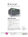
M a n u a l
f o r O p e r a t i o n
VDS 200 series
Voltage Drop Simulator pulses 2b, 4
VDS 200N10, N15, N30 N50
VDS 200N100, N150 N200
VDS 200N30.1 N50.1
VDS 200N100.1 N100.2 N100.3 N100.4
N100.5 N100.6
VDS 200N150.1
VDS 200N200.1 N200.2 N200.3 N200.4
RDS 200N
Testing of electronic modules in 12V/24V or 42V supply
systems.
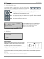
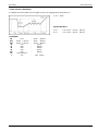
The VDS 200Nx is a low frequency amplifier. It simulates the
battery power supply of a vehicle and complex power supply
distortions in the power range up to 12'000W. A lot of different
waveforms are integrated as standard such as pulse 2b and
pulse 4 required in ISO 7637.
ISO 7637
SAE J1113
Manufacturer spec
GM, Ford, Chrysler,
BMW, VW, PSA,
Renault, Fiat ....
Version:
5.19 / 03.09.2013
the benchmark for emc
Replaces:
5.18 / 17.06.2013
Filename:
UserManual-VDS200Nx-E-V519.doc
Printdate:
03.09.13

EM TEST VDS 200 Series
Manual for Operation V 5.19 2 / 57
EM TEST Switzerland GmbH
Sternenhofstrasse 15
4153 Reinach BL1
Switzerland
Phone : +41 61 717 91 91
Fax : +41 61 717 91 99
URL : http://www.emtest.com
Copyright © 2013 EM TEST Switzerland GmbH All right reserved.
Specifications subject to change

EM TEST VDS 200 Series
Manual for Operation V 5.19 3 / 57
Contents
1. Model Overview ............................................................................................................................................. 5
1.1. VDS Models .................................................................................................................................................. 5
1.2. RDS Models .................................................................................................................................................. 7
2. Operating Functions ..................................................................................................................................... 8
2.1. Front view ..................................................................................................................................................... 8
2.2. Rear view ...................................................................................................................................................... 9
2.3. VDS200N100.1 operating elements ........................................................................................................... 11
2.3.1. Front view VDS200N100.1 ......................................................................................................................... 11
2.3.2. Rear view VDS200N100.1 .......................................................................................................................... 12
2.4. VDS 200N100.4 operating elements .......................................................................................................... 13
2.4.1. Overvoltage protection VDS200N100.4 ...................................................................................................... 13
2.5. VDS 200N100.6 operating elements .......................................................................................................... 14
2.6. Safety with voltage setting .......................................................................................................................... 15
3. Operation ...................................................................................................................................................... 16
3.1. Description of the menus ............................................................................................................................ 16
3.2. Main Menu .................................................................................................................................................. 16
3.2.1. Change of parameters ................................................................................................................................ 17
3.3. Wave Simulator ........................................................................................................................................... 18
3.3.1. ISO 7637 ..................................................................................................................................................... 19
3.3.1.1. Pulse 4 voltage drop .................................................................................................................................. 19
3.3.1.2. Pulse 2b ...................................................................................................................................................... 19
3.3.2. ISO 16750-2 WD 03/2000-2 ....................................................................................................................... 20
3.3.2.1. Short voltage drop ....................................................................................................................................... 20
3.3.2.2. Slow decrease / increase ............................................................................................................................ 20
3.3.2.3. Supply voltage profile.................................................................................................................................. 21
3.3.2.4. Pulse ’Starting profile’ ................................................................................................................................. 21
3.3.2.5. Sinus Sweep ............................................................................................................................................... 22
3.3.2.6. Overvoltage Vmax ...................................................................................................................................... 22
3.3.3. Jaso Test 1 ................................................................................................................................................. 23
3.3.4. Functions .................................................................................................................................................... 24
3.3.4.1. Sine wave ................................................................................................................................................... 24
3.3.4.2. Jump Start ................................................................................................................................................... 25
3.3.4.3. VDS Extern via the analogue input ............................................................................................................. 25
3.3.4.4. Pulse 4 ( GM 9105 P) ................................................................................................................................. 26
3.3.4.5. DC source ................................................................................................................................................... 27
3.4. Service ........................................................................................................................................................ 28
3.5. Setup ........................................................................................................................................................... 29
4. Test Equipment ............................................................................................................................................ 30
4.1. Construction ................................................................................................................................................ 30
4.2. Control unit .................................................................................................................................................. 30
4.3. Arbitrary Wave Simulator ............................................................................................................................ 31
4.4. Fuses .......................................................................................................................................................... 32
4.5. Overvoltage protection ................................................................................................................................ 33
4.5.1. Protection voltage level setting ................................................................................................................... 33
4.5.2. Function ...................................................................................................................................................... 34
4.5.3. Protection levels .......................................................................................................................................... 34
4.5.4. Level settings by the user ........................................................................................................................... 35
4.5.5. Typical protection behavior ......................................................................................................................... 36

EM TEST VDS 200 Series
Manual for Operation V 5.19 4 / 57
5. Technical Data ............................................................................................................................................. 37
5.1. Test level ..................................................................................................................................................... 37
5.2. Trigger ......................................................................................................................................................... 37
5.3. Input/output ................................................................................................................................................. 37
5.4. Interfaces .................................................................................................................................................... 37
5.5. General ....................................................................................................................................................... 38
5.6. Test routines ............................................................................................................................................... 39
5.7. Measurement .............................................................................................................................................. 39
5.8. Special models ............................................................................................................................................ 39
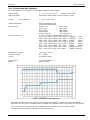
5.9. Technical data VDS 200N100.2 ................................................................................................................. 40
5.10. Technical data VDS 200N100.6 ................................................................................................................. 41
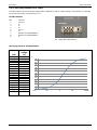
5.10.1. DUT voltage limitation on DC output .......................................................................................................... 42
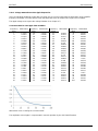
5.10.2. Voltage attenuation at sine ripple frequencies ............................................................................................ 43
6. Maintenance ................................................................................................................................................. 44
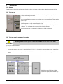
6.1. General ....................................................................................................................................................... 44
6.2. Test set-up .................................................................................................................................................. 44
6.3. Test set-up with software iso.control .......................................................................................................... 44
6.4. Examples Test setup .................................................................................................................................. 45
6.5. Calibration and Verification ......................................................................................................................... 47
6.5.1. Factory calibration ....................................................................................................................................... 47
6.5.2. Guideline to determine the calibration period of EM Test instrumentation ................................................. 47
6.5.3. Calibration of Accessories made by passive components only: ................................................................. 47
6.5.4. Periodically In-house verification ................................................................................................................ 47
7. Delivery Groups ........................................................................................................................................... 48
7.1. Basic equipment ......................................................................................................................................... 48
7.2. Accessories and options ............................................................................................................................. 48
8. Appendix ...................................................................................................................................................... 49
8.1. Declaration of CE-Conformity ..................................................................................................................... 49
8.2. RDS 200N ................................................................................................................................................... 50
8.2.1. Frontside RDS 200N ................................................................................................................................... 50
8.2.2. Rearside RDS 200 ...................................................................................................................................... 51
8.2.3. Technical data RDS 200N .......................................................................................................................... 52
8.2.4. Application .................................................................................................................................................. 52
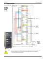
8.3. VDS 200N Blockdiagram ............................................................................................................................ 53
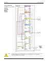
8.4. Bipolar VDS 200N Potential diagram .......................................................................................................... 54
8.5. Connectors .................................................................................................................................................. 55
8.6. Spare parts transistors ................................................................................................................................ 56
8.7. VDS 200N Menu overview ......................................................................................................................... 57

EM TEST VDS 200 Series
Manual for Operation V 5.19 5 / 57
1.
Model Overview
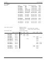
1.1.
VDS Models
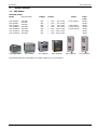
Standard models
Model Voltage
Name till 2008
voltage
current Inrush
Sinus
f max
VDS 200N10 60V
VDS 200B0
60V
I = 0A – 10A ± 10% ( 15A 500ms )
50kHz
VDS 200N15 60V
VDS 200B
60V
I = 0A – 15A ± 10%
50kHz
VDS 200N30 60V
VDS 200B1
60V
I = 0A – 30A ± 10% ( 70A 500ms )
50kHz
VDS 200N50 60V
VDS 200B2
60V
I = 0A – 50A ± 10% ( 100A 500ms )
30kHz
VDS 200N100 60V
VDS 200B3
60V
I = 0A – 100A ± 10% ( 150A 500ms )
30kHz
VDS 200N150 60V
VDS 200NB4
60V
I = 0A – 150A ± 10%
30kHz
VDS 200N200 60V
VDS 200B5
60V
I = 0A – 200A ± 10%
30kHz
VDS 200N10&15
VDS 200N30
VDS 200N50
VDS 200N100
VDS 200N150
VDS 200N200
Overvoltage protection (selectable max output Voltage 20, 30, 40 and 60V)

EM TEST VDS 200 Series
Manual for Operation V 5.19 6 / 57
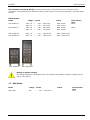
Special models
Special models have the index VDS200N200.x. The difference to standard models is the voltage and current
ranges. The operation is the same as by the standard VDS equipment’s. The maximum overcurrent trips at the
rated current.
Model voltage
current Inrush
Sinusfunction
f max
VDS 200N100.1 80V
I. = 0A- 100A ± 10% 150A 500ms
VDS 200N100.3 30V
I. = 0A- 100A ± 10% 150A 500ms
VDS 200N100.4 60V
I. = 0A- 100A ± 10% 150A 500ms
Overvoltage protection
(selectable 20, 30, 40 and 60V)
VDS 200N100.5 60V
I. = 0A- 100A ± 10% 150A 500ms
Extra fast slope
VDS 200N150.1 60V
I. = 0A- 150A ± 10% 500A 200ms
VDS 200N200.1 60V
I = 0A – 200A ± 10% 450A 400ms
750A 200ms
1000A 100ms
30kHz
VDS 200N200.2 30V
I = 0A – 200A ± 10% 2000A 500ms
1Hz – 20kHz 16Vpp
20kHz – 30kHz 10Vpp
30kHz – 50kHz 6Vpp
VDS 200N200.3 32V
I = 0A – 200A ± 10% 250A 500ms
VDS 200N200.4 30V
I = 0A – 200A ± 10% 1000A 500ms
Up VDS 200B5 S1
VDS200N100.3
VDS 200N100.4
VDS 200N200.3
VDS 200N200.4

EM TEST VDS 200 Series
Manual for Operation V 5.19 7 / 57
Special Models not listed in this list are customized versions. These devices have a Firmware version
x.xxaxxsxx. Some parameters can differ to the specs of this manual. The rest of the operation is according to this
manual.
Bipolar models
Model voltage
current inrush
sinus function
f max
VDS 200N30.1 +30V, -5V
+60V, -5V
I = 0A – 50A ± 10% 150A 200ms
I = 0A – 30A ± 10% 90A 200ms
50kHz
VDS 200N50.1 +30V, -5V
+60V, -5V
I = 0A – 85A ± 10% 220A 200ms
I = 0A – 50A ± 10% 150A 200ms
50kHz
VDS 200N100.2 +40V, -5V
VDS 200N100.6 +70V, -5V
I = 0A – 100A ± 10% 500A <10ms (32V)
I = 0A – 100A ± 10% 500A <10ms (15V)
VDS 200N50.1
VDS 200N100.6
Display of negative voltages
The voltage indication in the display shows only positive output voltages. Negative voltages are not
shown in the display.
1.2.
RDS Models
Model voltage
current inrush
sinus function
f max
RDS 200N 16V
I = 0A – 10A ± 10%
5kHz

EM TEST VDS 200 Series
Manual for Operation V 5.19 8 / 57
2.
Operating Functions
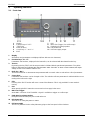
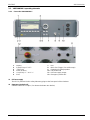
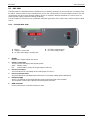
2.1.
Front view
1 Display
2 Function keys "F1..F7"
3 "TEST ON"
4 Knob (Inc/Dec)
5 Cursor keys "" and ""
6 EXIT
7 ESC
8 BNC CRO Trigger ( for oscilloscope)
9 Earthplug for voltage probes
10 LED Power ON
11 DUT test supply output
1 Display
All functions and parameters are displayed (8 lines with max. 40 characters).
2 Function keys "F1 .. F7"
Parameters and functions, displayed in the lowest line, can be selected with the related function key.
3 Test On
By pressing the key "TEST ON" the test procedure is initiated with the preselected parameters. The yellow
button is illuminated and indicates the Test ON status. After “Test OFF” or when no test is started, the output
voltage and the current will be setted to zero.
4 Knob (Inc / Dec)
The knob increments or decrements test parameters with a numeric value or selects from a list of parameters.
5 Cursor keys
Parameters and functions can be changed on-line. The selection of these parameters is realized with the cursor
moving to the left or to the right.
6 Exit
Pressing of the "EXIT" function will cause a reset of the firmware. This is only possible if no test routine is
running.
7 ESC
When pressing the ESC button the user moves back one page in the menu.
8 BNC CRO Trigger
At the BNC connector CRO TRIGGER a signal is available to trigger an oscilloscope.
9 Earth plug for voltage probes
During the verification this plug is the earth reference.
10 LED Power ON
This LED is on during the power on status.
11 EUT test supply
The EUT is powered via the safety laboratory plugs at the front panel of the simulator.

EM TEST VDS 200 Series
Manual for Operation V 5.19 9 / 57
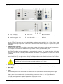
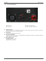
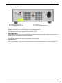
2.2.
Rear view
1 EUT Test supply
2 Reference earth connection
3 Analogue input 0 - 10V
4 External trigger
5 Mains input
6 Fuses
7 Power On switch
8 Parallel interface IEEE 488
9 USB Interface
10 CN connector not used
11 Fail 1
12 Fail 2
1 Test supply output
At this output the generator can be loaded with the maximum current of 15A // 30A // 35A // 50A // 100A
depending on the type of generator. This output is also used for the internal wiring in a complete rack system
installation.
2 Reference earth connection
During immunity tests it may be useful to connect the simulator with reference earth plane of the test set-up.
For complete rack installations all different test generators shall be grounded at this point.
3 Analogue input 0-10V
The internal amplifier can be controlled by an external signal generator. The operator therefore shall select
the User Test Routines of the VDS part and start the menu Extern. The amplifier than is ready to be remote
controlled.
The input signal range is 0-10V in the frequency range of 0-50kHz. The output power (EUT test supply) than
would result in 0-30V or 0-60V and a nominal current depending on the type of instrument. The frequency
range is 50kHz for up to 6Vpp and 25kHz for up to 16Vpp.
For Frequency >50kHz to 100kHz the VDS output voltage must be limited to max. 3Vpp.
Therefore the analogue input signal must be limited to max. 0.7Vpp !
4 External trigger
One single event with preselected parameters can be released. Trigger level is 5-15V positive going.
5 Mains input
230V 16A input connector. This connector depends on the VDS model
6 Fuses
This fuses depends on the VDS model. F4 is the control fuse (2Aslow blow) for units with 3-phase supply.
7 Power On switch
230V system: The Power On switch includes also the power mains fuses (2 x 10A T) and filter unit.
115V system: The Power On switch, fuses and the filter unit are separated due to the higher currents.
For high current generators a 3phase power mains supply has to used.
For detailed technical data see chapter 5.5. General

EM TEST VDS 200 Series
Manual for Operation V 5.19 10 / 57
1 EUT Test supply
2 Reference earth connection
3 Analogue input 0 - 10V
4 External trigger
5 Mains input
6 Fuses
7 Power On switch
8 Parallel interface IEEE 488
9 USB Interface
10 CN connector not used
11 Fail 1
12 Fail 2
8 Parallel interface IEEE 488 // GPIB
IEEE 488 interface with IEEE connector.
9 USB interface
USB interface “USB B” connector. For datatransfer a USB interface is available. The internal RS 232 interface is
converted to USB standard. Therefore the user must set the same Baudrate in the device and control software.
Using the USB interface the user can have emc problems during burst tests Our experiences says, that usually
the computer USB port is disturbed by interference’s. Therefore a high quality USB cable ( USB 2.0 standard)
must be used.
10 CN connector not used
Connector for control external devices not used in VDS200N series.
11 Fail detection FAIL 1 (TEST STOP)
The BNC input FAIL 1 can be used for failure detection at the EUT. If the input is set to ground (chassis) the
VDS generator will be stopped and the actual test routine is paused. The test routine than can be stopped
completely or can be continued at the break point.
A message of FAIL 1 is indicated in the LCD display as well as in the ISM software.
12 Fail detection FAIL 2 (TEST PAUSE)
The BNC input FAIL 2 can be used for failure detection at the EUT. If the input is set to ground (chassis) the
actual test routine is paused as long as the low level signal is available at the FAIL 2 input.
With no longer set to ground signal the test procedure continues automatically.
A message of FAIL 2 is indicated in the LCD display as well as in the ISO.CONTROL software.

EM TEST VDS 200 Series
Manual for Operation V 5.19 11 / 57
2.3.
VDS200N100.1 operating elements
2.3.1.
Front view VDS200N100.1
1 Display
2 Function keys "F1..F7"
3 "TEST ON"
4 Knob (Inc/Dec)
5 Cursor keys "" and ""
6 EXIT
7 ESC
8 BNC CRO Trigger ( for oscilloscope)
9 Earthplug for voltage probes
10 LED Power ON
11 DUT test supply output
12 Emergency switch OFF
11 EUT test supply
The EUT is powered via the safety laboratory plugs at the front panel of the simulator.
12 Emergency Switch OFF
Switches off the DUT output. ( for release the button turn before)

EM TEST VDS 200 Series
Manual for Operation V 5.19 12 / 57
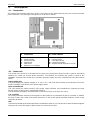
2.3.2.
Rear view VDS200N100.1
12 Main Switch
13 Sense input
14 DUT Test supply output
15 Mains input CEE 3x400V 16A
12 Power On switch
The power on switch is a circuit breaker model Siemens 3RV10 21-1JA1 with overcurrent protection. For switch on
the user has to put the switch in the illustrated position.
13 Sense input
Sense input for dc supply. (2x banana plug 4mm)
14 DUT Test supply output
At this 6mm output the generator can be loaded with the maximum This plugs are in parallel to the plugs
“TEST SUPPLY” at the front side.
15 Mains CEE 3x400V 16A
3 x 400/ 50Hz 6kVA
CEE plug type Mennekes 2069
3x400/16A L1, L2, L3, N, PE

EM TEST VDS 200 Series
Manual for Operation V 5.19 13 / 57
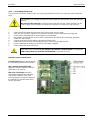
2.4.
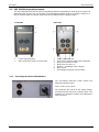
VDS 200N100.4 operating elements
The VDS 200N100.4 includes an internal overvoltage protection selectable by a switch at the rear side. The
protection levels are 20V, 30V, 40V and 60V. The overvoltage protection works as a crowbar, switches in a
few µs and discharges the storage capacitor bank and switches off the charging rectifier.
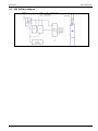
Front side
Rear side
1 Power output frontside
2 Mains plug 230V fused on F4 total 16A
1 Power output rear side
2 Fuse F4 for all mains output 16AT (6x32mm)
3 Mains 230V fused total 16A
4 Mains input 3 x 400 V ac
5 Fuse F1…F3 32A gG (10.3 x 38mm)
6 Main Switch
7 Overvoltage protection selector switch
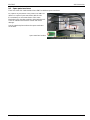
2.4.1.
Overvoltage protection VDS200N100.4
The overvoltage protection switch selects the
following protection levels:
20.0V, 30.0V, 40.0V, 60.0V
The protection will switch off the output voltage
and discharge the internal dc-capacitor bank. The
protection is a hardware solution and independent
of the controller.

EM TEST VDS 200 Series
Manual for Operation V 5.19 14 / 57
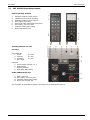
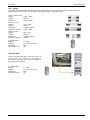
2.5.
VDS 200N100.6 operating elements
General operating elements
1 Autowave (optional control device)
2 VDS200 front for manual operating
3 Emergency button (turn for release)
4 DUT supply ,sense front
5 Rear panel (VDS and Autowave functions)
6 DUT supply , sense rear side
7 Protection switch power supply
8 Mains input 4x400V 32A
Operating elements rear side
A Control
VDS 200N100.1
1 I Peak 1V = 50A
2 I Monitor 1V= 10A
3 U Monitor 1V= 10V
4 Ext Trigger
Autowave
5 Analog output channels 2, 3, 4
6 USB interface
7 Ethernet interface
8 GPIB IEEE 488 interface
B VDS 200N100 power part
9 Earth connection
10 DUT supply , sense rear side
11 Protection switch power supply
12 Mains input 4x400V 32A
The description of the Autowave interface and plugs refer to the Autowave manual.

EM TEST VDS 200 Series
Manual for Operation V 5.19 15 / 57
2.6.
Safety with voltage setting
To ensure a safe operation of the DUT (Device Under Test) some restrictions in the operation of the instrument
are built in. These restrictions are explained within this paragraph.
The VDS basically is divided into 2 different operation modes, which includes their individual test routines and
supply voltage setting. The four different modes can be listed as follows:
DC Source (VDS Generator - User Test Routines - DC Source)
Within this mode the VDS is used as a simple DC power source in the range of 0-60V // 0-15A // 30A // 50A //
100A // 200A and an integrated current limiter.
Arbitrary Wave Simulator
Within this mode the VDS generates arbitrary waveforms and signals which are specified in different standards,
such as pulse 4 of ISO 7637.
All these different test modes are changing generally the voltage supply setting of the generator in a different
way. This would mean a certain risk for the operator to burn out the connected DUT by higher dc supply voltages
as intended. Therefore it is decided to clearly separate the two test modes by the following structure listed :
1. DC source
When entering the Arbitrary Wave test mode the dc output voltage of the VDS 200 is automatically set to the
nominal voltage of the DUT. The actual nominal voltage can be defined in the service menu under "Set-up".
When starting the related test routines the output voltage will be generated as per the setting shown up in the
display for each individual test routine.
- The operator can accept this setting and start the test immediately .
- The operator can first change the parameters and than start the test.
When leaving the test mode DC source the output voltage is automatically reset to the nominal supply voltage of
the DUT. The previous voltage setting will be stored in the test file.
2. Arbitrary Wave Simulator
When selecting the Arbitrary Wave mode the output voltage will be set automatically to the nominal voltage of the
DUT. The actual nominal voltage can be defined in the service menu under "Set-up".
When starting the related test routines the output voltage will be generated as per the setting shown up in the
display for each individual test routine.
- The operator can accept this setting and start the test immediately.
- The operator can first change the parameters and then start the test.
When leaving the test mode Arbitrary Wave Simulator the output voltage is automatically reset to 0V. The
previous voltage test parameters will be stored and can be used for the next test.
The consequence of the structure is that between the different test modes
the DUT supply is automatically switched off.

EM TEST VDS 200 Series
Manual for Operation V 5.19 16 / 57
3.
Operation
3.1.
Description of the menus
The simulator VDS 200 is operated by an easy menu control system.
Seven function keys are available to select parameters and functions. All
functions are indicated on the display; max. 8 lines and 40 characters.
The selected parameter is blinking and can be changed by turning the knob (incr./decr.).
: The digit to be changed can be selected with the cursor ( ).
- Setted values are direct indicated on the screen.
- Status on the bottom lines shows the desired status after pressing the function key.
ESC : ESC will take you back to the previous level in the menu and set the displayed
values. The latest settings are stored automatically and will be recalled when the
menu is selected again.
EXIT : The firmware will reset to the main screen.
EM TEST
V D S 2 0 0 N 10
Voltage Drop Simulator
V 3.04
Waveforms
SWN: 001234
The serial number and the version number SWN are
used for tractability reasons. These numbers are listed
in the test reports and calibration certificates. These
numbers also are listed within the test reports
generated by the iso.control software
Start-up display example VDS 200N10
3.2.
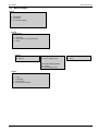
Main Menu
MAIN MENU
F1 : Wave Simulator
F7 : Service
F1
F2
F3
F4
F5
F6
F7
F1 Wave Simulator.
Within this part the internal low frequency high power amplifier
together with the internal signal generator is used to generate
arbitrary waveforms as required in different standards.
The operator can use the generator in this mode as a
- DC power supply source
- High power arbitrary wave generator with integrated test routines
- or simply as a Low Frequency Amplifier
The low frequency amplifier can be remote controlled by any external arbitrary generator. External generators
shall be connected at the rear part of the equipment. Any waveform can be generated up to the upper bandwidth
of the unit.
F7 Service
Set-up, self-test, addresses of EM Test can be selected and displayed.

EM TEST VDS 200 Series
Manual for Operation V 5.19 17 / 57
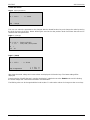
3.2.1.
Change of parameters
Easy and very fast operation of all standard functions of the equipment. The latest simulator settings are stored
automatically and will be recalled when Quick Start is next selected.
Page 5 (Show parameters)
ISO Pulse 4
Vb = 12.0V Va1 = -7.0V
Va2 = -3.0V t1 = 0.2s
t6 = 5ms t7 = 5ms
t8 = 5ms tf = 5ms
Va = 13.5V tri = Auto
I = 30A
Start Change
F1
F2
F3
F4
F5
F6
F7
Press START and the test routines begin to work.
Press CHANGE and the actual parameter can be changed.
Page 6 (Change of page 1/2) Page 6 (Change of page 2/2)
ISO Pulse 4
ISO Pulse 4
Vb: 0.0V - 60.0V
t8: 0.1 s - 99.9 s
Vb Va1 Va2 t1 t6 t7
t8 tf Va tri I
12.0 -7.0 -3.0 0.2 5 5 1/2
13.5 5 13.5 Auto 30 2/2
F1
F2
F3
F4
F5
F6
F7
F1
F2
F3
F4
F5
F6
F7
The user can select the parameter to be changed with the related function key and change the value by turning
the knob. The cursor allows the user to define the value of the digit to be changed (fast or slow change).
Pressing of the ESC button will bring the user back to the previous level from where the test can be
restarted with new parameters.
Page 6 (Start)
ISO Pulse 4
After start the actual voltage and current measurements
are displayed. All function keys except F2 (Man) within
the manual trigger mode can stop the test routine. The
latest setting will be displayed.
Pressing the key F3 while the test is running, the
display change to the ZOOM mode and is indicating the
actual voltage and current measurement in big letters.
Vb = 12.0V Va1 = -7.0V
Va2 = -3.0V t1 = 0.2s
t6 = 5ms t7 = 5ms
t8 = 5ms tf = 5ms
Va = 13.5V tri = Auto
I = 30A I = 3.5 A
Stop Zoom V = 7.0 V
F1
F2
F3
F4
F5
F6
F7
Page 6 (Stop)
ISO Pulse 4
By pressing any function key the Start, Change or
Continue mode will come up in the display. F3 will
continue the same test routine. Also the test time will
continue running. If the user first selects Start or
Change, the test will be stopped completely.
Vb = 12.0V Va1 = -7.0V
Va2 = -3.0V t1 = 0.2s
t6 = 5ms t7 = 5ms
t8 = 5ms tf = 5ms
Va = 13.5V tri = Auto
I = 30A I = 3.5 A
Stop Zoom V = 7.0 V
F1
F2
F3
F4
F5
F6
F7
Start Change Cont.
F1
F2
F3
F4
F5
F6
F7

EM TEST VDS 200 Series
Manual for Operation V 5.19 18 / 57
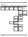
3.3.
Wave Simulator
Page 2
Waveform Simulator
F1 : Standards
F2 : Functions
F3 : DC Power Supply
F1
F2
F3
F4
F5
F6
F7
Page 3
STANDARDS
F1 : ISO 7637
F2 : ISO 16750-2 or WD 03/2000-2
F3 : JASO
F1
F2
F3
F4
F5
F6
F7
Pages 4
ISO 7637
ISO 16750-2 WD 03/2000-2
JASO
F1: Pulse 4
F1: Short voltage drop
F1: Jaso
F2: Pulse 2b
F2: Slow decrease / increase
F3: Supply voltage profile
F4: Pulse ’Starting profile’
F5: Sweep
F6: Overvoltage Vmax
Page 3
FUNCTIONS
F1 : Sinus
F2 : Jumpstart
F3 : VDS Extern
F4 : Pulse 4 (GM 9105P)
F1
F2
F3
F4
F5
F6
F7

EM TEST VDS 200 Series
Manual for Operation V 5.19 19 / 57
3.3.1.
ISO 7637
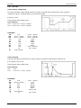
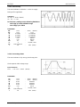
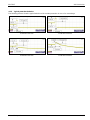
3.3.1.1.
Pulse 4 voltage drop
This pulse simulates supply voltage reduction caused by energizing the starter-motor circuits of internal
combustion engines, excluding spikes associated with starting.
tf [Vb-Va1] < 5ms
Limits depends VDS voltage range
Input restrictions
0.0 V <= Vb + Va1 <= 30.0V (60.0V)
0.0 V <= Vb + Va2 <= 30.0V (60.0V)
Parameters:
Vb
0.0V
-
30.0V (60.0V)
Va1
- 30.0V (- 60.0V)
-
30.0V (+ 60.0V)
Va2
- 30.0V (- 60.0V)
-
30.0V (+ 60.0V)
t1
0.1s
-
99.9s
t7
5ms
-
999ms
t8
5ms
-
999ms
t9
0.1s
-
99.9s
t11
5ms
-
999ms
Va
0.0V
-
30.0V (+ 60.0V)
I
1A
-
30A (Imax)
tri
Auto / Manual
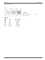
3.3.1.2.
Pulse 2b
This pulse simulates transients from dc motors acting as generators after ignition is switched off.
tr, tf ( 10/90%) =1ms 50%
Limits depends VDS voltage range
Input restrictions
Va1 0.0V
0.0 V Vb + Va1 30.0V (60.0V)
Parameters:
Vb
0.0V
-
30.0V (60.0V)
Va1
- 30.0V (- 60.0V)
-
0.0V
t1
0.1s
-
99.9s
t6
1ms
-
999ms
td
5ms
-
9999ms
int
0.1s
-
99.9s
n
1
-
30,000 / endl.
tri
Auto / Manual
I
1A
-
30A (Imax)

EM TEST VDS 200 Series
Manual for Operation V 5.19 20 / 57
3.3.2.
ISO 16750-2 WD 03/2000-2
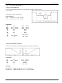
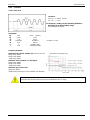
3.3.2.1.
Short voltage drop
This test is to simulate the effect of a classical fuse actuation in another circuit.
tr, tf = 10ms
Limits depends VDS voltage range
Input restrictions
0.0 V Vb + Va1 30.0V (60.0V)
0.0 V Vb + Va2 30.0V (60.0V)
Parameters:
Vb
0.0V
-
30.0V (60.0V)
Va1
- 30.0V (- 60.0V)
-
30.0V (60.0V)
Va2
- 30.0V (- 60.0V)
-
30.0V (60.0V)
t1
0.1s
-
99.9s
t2
0.1s
-
99.9s
t3
0.1s
-
99.9s
int
0.1s
-
99.9s
n
1
-
30,000 / endl.
tri
Auto / Manual
I
1A
-
30A (Imax)
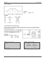
3.3.2.2.
Slow decrease / increase
This test is to simulate a gradual discharge and recharge of the battery.
Parameters:
V1
0.0V
-
30.0V (60.0V)
V2
- 30.0V (- 60.0V)
-
30.0V (60.0V)
t1
0.1s
-
99.9s
t2
0.1s
-
9999.9s
I
1A
-
30A (Imax)
Remarks:
WD 03/2000-2 Voltage change rate = ( 3 0.1 ) V per minute
ISO 16750-2 Voltage change rate = ( 0.5 0.1 ) V per minute
Page is loading ...
Page is loading ...
Page is loading ...
Page is loading ...
Page is loading ...
Page is loading ...
Page is loading ...
Page is loading ...
Page is loading ...
Page is loading ...
Page is loading ...
Page is loading ...
Page is loading ...
Page is loading ...
Page is loading ...
Page is loading ...
Page is loading ...
Page is loading ...
Page is loading ...
Page is loading ...
Page is loading ...
Page is loading ...
Page is loading ...
Page is loading ...
Page is loading ...
Page is loading ...
Page is loading ...
Page is loading ...
Page is loading ...
Page is loading ...
Page is loading ...
Page is loading ...
Page is loading ...
Page is loading ...
Page is loading ...
Page is loading ...
Page is loading ...
-
 1
1
-
 2
2
-
 3
3
-
 4
4
-
 5
5
-
 6
6
-
 7
7
-
 8
8
-
 9
9
-
 10
10
-
 11
11
-
 12
12
-
 13
13
-
 14
14
-
 15
15
-
 16
16
-
 17
17
-
 18
18
-
 19
19
-
 20
20
-
 21
21
-
 22
22
-
 23
23
-
 24
24
-
 25
25
-
 26
26
-
 27
27
-
 28
28
-
 29
29
-
 30
30
-
 31
31
-
 32
32
-
 33
33
-
 34
34
-
 35
35
-
 36
36
-
 37
37
-
 38
38
-
 39
39
-
 40
40
-
 41
41
-
 42
42
-
 43
43
-
 44
44
-
 45
45
-
 46
46
-
 47
47
-
 48
48
-
 49
49
-
 50
50
-
 51
51
-
 52
52
-
 53
53
-
 54
54
-
 55
55
-
 56
56
-
 57
57


Ask a question and I''ll find the answer in the document
Finding information in a document is now easier with AI
Other documents
-
partyrent com 400V-4kW-16A User manual
-
Eterna EBPM3 Owner's manual
-
Projecta Easy Install RF CH Specification
-
 Scientific SME1130D Owner's manual
-
Abus BT2012 Datasheet
-
HP 240A Service and Maintain
-
 DROK DC Buck Module, Adjustable Buck Converter Step Down Voltage Regulator 6V-32V 30V 24V 12V to 1.5-32V 5V 5A LCD Power Supply Volt Reducer Transformer Module Board User manual
-
 Mitsubishi Electronics AG-150A User manual
-
Philips OVU412000/RC1974506 Datasheet
-
Listen NAVILUTION PA Delivery Demo Quick start guide


