
Med Aire Plus 10”
Alternating Pressure and
Low Air Loss Bariatric Mattress
Replacement System
www.drivemedical.com
USER MANUAL
Item #s 14030, 14048, 14054, 14060
(Control unit 14030XP)

2
TABLE OF CONTENTS
IMPORTANT PRECAUTIONS .............................................................................................................3
DOCUMENT SYMBOLS ......................................................................................................................3
INTRODUCTION ..................................................................................................................................5
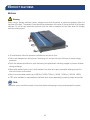
UNPACKING YOUR MED AIRE PLUS 10" ...........................................................................................6
PRODUCT FEATURES ........................................................................................................................7
Control Unit ...................................................................................................................................7
Mattress.........................................................................................................................................8
PRODUCT FUNCTION ........................................................................................................................9
Control Unit ...................................................................................................................................9
Mattress.......................................................................................................................................10
OPERATION. .....................................................................................................................................12
CPR Function ..............................................................................................................................12
Low Presure Indicator .................................................................................................................13
PATIENT POSITIONING AND COMFORT .........................................................................................13
CLEANING AND MAINTENANCE .....................................................................................................14
TROUBLESHOOTING .......................................................................................................................16
SPECIFICATIONS .............................................................................................................................. 17
WARRANTY .......................................................................................................................................18
This manual should be used for the initial set up of the system and for future reference.

3
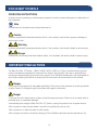
DOCUMENT SYMBOLS
OPERATING INSTRUCTIONS
Indicates correct operating or maintenance procedure in order to prevent damage to or destruction of
the equipment.
Note
Indicates tips or information users should be aware of.
Caution
Indicates a potentially hazardous situation which, if not avoided, could result in property damage or
minor injury or both.
Warning
Indicates a potentially hazardous situation which, if not avoided, could result in death or serious injury.
Danger
Indicates an imminently hazardous situation which, if not avoided, will result in death or serious injury.
The Med Aire Plus 10” System, 14030 | 14048 | 14054 | 14060, is a Class 2 medical device and that
must be installed and operated in the manner for which it was intended. The user is responsible for
reading and understanding the product user manual. Drive DeVilbiss Healthcare is not responsible for
any injuries resulting from failure to comply with the instructions and precautions in this manual.
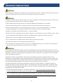
Danger
Do not use in the presence of ammable anesthetics. Do not use in the presence of smoking materials
or open ames. Air owing through the mattress will support combustion.
Danger
To reduce the risk of electrocution, adhere to the following instructions. Failure to do so could result in
personal injury or equipment damage.
• Immediately after using the Med Aire Plus 10” System, unplug this product from its power source.
• Do not place or store product where it can fall or be pulled into a tub or sink.
• Do not place in or drop into water or other liquids.
• Do not open the control unit without referring to Drive DeVilbiss technical service department rst.
IMPORTANT PRECAUTIONS

4
IMPORTANT PRECAUTIONS
Warning
Do not strap the mattress to the bed frame at the head and foot ends. Secure mattress straps to the bed
deck at the head and foot ends and to the bed frame at the center of the bed.
Warning
To reduce the risk of burns, electrocution, re, or injury, adhere to the following instructions. Failure to do
so could result in personal injury or equipment damage.
• This product should only be used for its intended purpose as described in this manual.
• Only use attachments and /or accessories that are recommended by the manufacturer.
• Do not use this product if it has a damaged cord or plug, if it is not working properly, if it has been
dropped, damaged, or immersed in water. Return to your provider for a warranty claim.
• Keep the cord away from heated surfaces, i.e. space heaters.
• Never block the air openings of the product or place it on a soft surface, such as a bed or couch, where
the air openings may be blocked. Keep the air openings free of debris such as lint and hair.
• Never drop or insert any object into any opening or hose.
• Do not use outdoors or operate where aerosol (spray) products are used.
• Connect this product to a properly grounded outlet only.
• Do not spill food or liquids onto the control unit. If a spillage does occur, turn off the unit, disconnect it
from its power supply and allow at least 24 hours for drying.
Warning
Drive DeVilbiss Healthcare support surfaces are designed as mattress replacement systems. The risk of
entrapment may occur when mattresses are placed on bed frames that do not properly t and leave gaps
between the mattress and head panel, foot panel and bed or side rails. This system is NOT to be used
when such gaps are present.
User/Facility staff are responsible for ensuring that all mattresses properly t the bed frames. Drive
DeVilbiss is not responsible for the improper placement of its systems on ill-tting bed frames. Health care
professionals assigned to each patient should make the nal determination whether side or assist rails are
warranted after assessing patient risks based on the individual’s needs and condition.
An optimal bed system assessment should be conducted on each patient by a qualied clinician or
medical provider to ensure maximum safety. The assessment should be conducted in compliance with
the state and federal guidelines related to the uses of restraints and bed system entrapment guidance
including but not limited to the below:
1) US FDA Entrapment Guidelines. “A Guide to Bed Safety,” https://www.fda.gov/medical-devices/
hospital-beds/guide-bed-safety-bed-rails-hospitals-nursing-homes-and-home-health-care-facts
2) US FDA Hospital Bed System Dimensional and Assessment Guidance to Reduce Bed Entrapment,
https://www.fda.gov/regulatory-information/search-fda-guidance-documents/hospital-bed-system-
dimensional-and-assessment-guidance-reduce-entrapment

5
INTRODUCTION
Pressure injuries are dened as localized injuries of the skin and/or underlying tissue over a bony
prominence as a result of pressure or pressure in combination with shear.
1
Support surfaces or
specialized mattress systems are used as part of an overall, multi-disciplinary, multi-dimensional care
plan intended to prevent and treat pressure injuries.
The Med Aire Edge Mattress Replacement System is a high quality powered air support surface
that is specically designed for the prevention and treatment of pressure injuries while optimizing
patient comfort.
Indications for Use
Note
Effective pressure redistribution therapy, wound management and device selection should be based on
the patient’s specic clinical condition and complete assessment of needs, recognizing that pressure
prevention devices are only one component of a comprehensive pressure injury management program.
Support surfaces are not substitutes for turning, repositioning or functional weight shifts.
The Med Aire system is intended for:
1) Pressure redistribution for individuals with but not limited to the following conditions:
• At risk or present pressure injuries
• Neurological conditions
• Amputations
• Grafts
• Burns
• Dermatological conditions
• Flaps
• Rehabilitation needs
• Pain management as prescribed by a physician.
2) Shear & Friction Reduction:
Friction is dened as the resistance of motion in a parallel direction relative to the common boundary of
two surfaces. For patients this can occur when the skin rubs against another surface.
1
European Pressure Ulcer Advisory Panel and United States National Pressure Ulcer Advisory Panel. Prevention and Treatment of
Pressure Ulcers: Clinical Practice Guidelines. National Pressure Ulcer Advisory Panel; 2009.

6
INTRODUCTION
UNPACKING YOUR MED AIRE PLUS 10"
Shear strain occurs when tissue is deformed or damaged due to shear stress or force exerted parallel to
the plane of interest. The Med Aire Plus 10” cover is constructed of quilted nylon material with low shear
and low friction properties to protect skin integrity.
3) Spinal Cord Injury:
The Med Aire Plus 10” system can be used for patient’s with spinal cord injury once the acute injury has
been stabilized and these patients have been assessed and cleared by the appropriate clinician.
European Pressure Ulcer Advisory Panel and United States National Pressure Ulcer Advisory Panel.
Prevention and Treatment of Pressure Ulcers: Clinical Practice Guidelines. National Pressure Ulcer
Advisory Panel; 2009.
Contraindications
Patient conditions for which the application of pressure relieving therapy on an alternation system is
contraindicated are as follows:
1) Cervical or skeletal traction
2) Unstable spinal cord injuries
1) Carefully remove all components from packaging.
2) Conrm that you have received the control unit intended.
3) Check all components for damages. Contact your medical provider if any components are damaged.
DO NOT use damaged components.

7
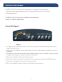
The Med Aire Plus 10” mattress replacement system is comprised of two components:
1) Therapy air cell mattress replacement with 10” high air cells and static 5” air cell base
2) Therapy control unit
The Med Aire Plus 10” control unit is available in one conguration:
Control Unit 14030XP: Digital System
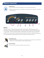
Control Unit (Figure 1)
Figure 1
• This digital control unit includes intuitive controls for adjusting the air pressure based on the patient’s
weight and comfort levels.
• Static button is available to discontinue alternation therapy for patient transfers, caregiving, comfort, or
preference.
• Low pressure, power failure and system failure indicators allow the user to be aware of any air pressure
changes, power outages or system malfunctions, respectively.
• Mute button available for silencing information signal.
• Seat inate increases air pressure for additional sacral support during head of bed (HOB) elevation.
• Cycle times are available to customize the therapy duration.
• Max rm is available for patient transfers or other patient care procedures.
PRODUCT FEATURES

8
PRODUCT FEATURES
Mattress
Warning
When using a therapy mattress system, always ensure that the patient is positioned properly within the
connes of the bed. The patient’s head should be positioned in the center of the top section of the therapy
mattress. Do not let any extremities protrude over the side or between the bed rails when the therapy
mattress is being used.
• 20 individual air cells offer pressure redistribution and low air loss.
• Cell-on-cell designed air cells prevent “bottoming out” and provide up to 24 hours of power outage
protection
• Quick cell disconnects allow for quick and easy cell replacement including stopper to prevent deation
during exchange.
• Removable quilted Nylon cover is uid resistant, low shear and vapor permeable helping protect the
skin from friction and moisture
• Able to accommodate patients up to 600 lbs (14030), 750 lbs. (14048), 1,000 lbs. (14054 & 14060).
• CPR valve available for rapid deation (deation time varies depending on patient weight and prole).
Note
Please be sure to read this manual in its entirety before attempting to set up and operate this system.

9
PRODUCT FUNCTION
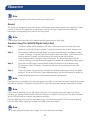
Control Unit 14030XP
Power switch is located on the side of the control unit. Use the power switch to turn the system off and on.
Cycle Time (1)
• The cycle time can be selected from the panel to choose the appropriate cycle time of the
ination modes.
• The cycle time value options are: 15, 20, 25, or 30 minutes.
Weight Settings (2)
• Weight settings range from ≤250-1,000 lbs and can be used to adjust the pressure of the
inated cells based on the patient’s weight and comfort level.
Mute Button (3)
• The audible/visible information signal turns on when low pressure, power failure or system
failure occur.
• To mute the audible information signal, press the Mute button. The visible information signal
indicator will continue ashing until the issue is resolved.
• Re-press the Mute button to reactivate the information signal.
Alternate Mode (4)
• Press to set the system to alternation therapy mode.
Static Mode (4)
• Press to set the system to static therapy mode. The system will revert to the previously
set alternation mode after 120 minutes.
Auto Firm (5)
• Press to set the air mattress to quick ination mode, which facilitates nursing and caring.
The system will revert to the previously set therapy mode after 30 minutes.
SeatInate(6)
• Press to set the air mattress to seat (fowler) mode. The pressure value will increase by
5mmHg to facilitate more comfortable seating.

10
PRODUCT FUNCTION
Lock Button (7)
• Auto: control unit panel automatically locks in 5 minutes without operation.
• Manual: press lock button for 3 seconds to lock the panel, press again for 3 seconds to
unlock the panel.
Mattress
The Med Aire Plus 10” Mattress Replacement (14030 | 14048 | 14054 | 14060) comes with a hose
connection at the foot end of the mattress and 20, 10” high individual air cells constructed with a static
5” air cell base. The cell-on-cell design prevents “bottoming out” and provides up to 24 hours of power
outage protection. The cell material, polyurethane and nylon blend, provides a specialty surface that
conforms to the specic shape of the patient, minimizing soft tissue distortion, reducing bone penetration
into muscle fascia, and promoting improved blow ow compared to traditional surfaces.
CPRDeationValve
• Pull the red CPR strap to release the air immediately from the mattress for rapid deation.
Deation time varies depending on patient weight and prole.
Quick Connector
• Used to connect the therapy mattress to the control units.
(2)
(4)(6)(5)(7)
(3)
(1)

11
Warning
For important precautions, see pages three and four
Caution
Do not place the control unit on the oor. Position the power cord to prevent tripping hazards
1) Remove all existing covers, sheets and mattress from the bed.
2) Unpack the Med Aire Plus 10” system and inspect all components for damage. Do NOT use the
system if any component is damaged.
3) Conrm there are no sharp objects in the immediate area which may risk damage to the Mattress
Replacement.
4) Position the Med Aire Plus 10” Mattress Replacement on top of bed, printed top cover facing upwards
and air hoses towards the foot end of the bed.
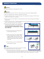
5) Secure the therapy mattress to the movable parts of
the bed frame or bed deck. Ensure buckles are
securely fastened and straps are pulled tightly.
DO NOT SECURE TO THE SIDE RAILS - STRAPS
WILL TEAR OFF.
a) Position the control unit by hanging hooks
over foot board of the bed.
b) Attach the air hoses to the therapy mattress
securely using the quick connector. When
properly installed, the quick connector will
audibly click into place. Ensure air hoses do
not kink between mattress, bed frame and
control unit.
c) Plug the power cord into an electrical outlet
with grounded AC power.
Note
Before inserting the plug into the outlet, make sure the voltage
is compatible and the product is well grounded.
d) Switch the power switch on the side of the control unit on. The mattress replacement system may
take up to 40 minutes for full ination regardless of the control unit being used. For rapid ination
an external pump may be used such as Drive’s electric quick ll pump, item #: 14427QF.
PRODUCT FUNCTION
5)
a)
b)
c)

12
Note
Always read the operating instructions in this manual before use.
General
This product is designed to provide pressure redistribution while maximizing comfort to patients. Please
be sure to operate this equipment as instructed to optimize its value. Please be sure to follow the
instructions corresponding to the control unit being used.
Note
Please follow instructions below for detailed operating procedure of each type.
Operation Using The 14030XP (Digital Control Unit)
Step 1 Turn on the power switch located on the side of the control unit. Next press the power
button on the front of the control power. A beep will sound to alert that the system is on.
Step 2 The control unit will automatically default to a static mode of therapy and begin inating
to reach 15 mmHg. It may take up to 40 minutes to reach full ination. If full ination is not
reached within 40 minutes, the low pressure information signal will illuminate.
Press the Mute button to mute the information signal. The information signal LED will
continue ashing. Press the Mute button again to re-enable the audible information signal.
Step 3 Press the Auto Firm button to automatically inate the mattress to the maximum level
(70 mmHg) for about 30 minutes. The pressure will return to a previously set level after
30 minutes.
Step 4 Once fully inated, the control unit will switch into alternating therapy mode at the default
setting of 15 min and 20mmHg. Select desired settings from the touch panel to adjust the
cycle time and pressure level to the patients’ specic requirements.
Note
Press the Autorm mode button from the touch panel to provide a rm surface that makes it easier for the patient
to transfer or reposition. The system will revert back to the previously selected therapy mode after 30 minutes.
Note
During normal operation, the unit will monitor pressure. If the mattress pressure is lower than the set
pressure, the pump will automatically inate the mattress to readjust to the set level. The alarm will beep
and its LED will come on to alert a low pressure condition.
Press the Mute button to mute the information signal. The information signal LED will continue ashing.
Press the Mute button again to re-enable the audible information signal.
Note
For suitable pressure, please refer to page 14 for the hand check procedure.
OPERATION

13
CPR Function
When there is an emergency requirement to perform CPR on the patient, pull the CPR strap at the head
section of the mattress to release the air quickly from the mattress.
Pressure Range Selection (+/-)
Users can adjust the pressure level of the air mattress, using the (+) and (-) buttons, to a desired rmness
based on personal comfort or weight setting.
Note
It is recommended to press Auto Firm on the panel when the mattress is rst inated. Users can then
easily adjust the air mattress to a desired rmness according to the patient’s weight and comfort.
Low Pressure Indicator
When the air pressure in the system falls below the selected pressure range, a low pressure condition will
signal the low pressure indicator. Check if the connections are secure and correctly installed according to
the relevant instructions.
Note
If the pressure is consistently low, open the zipper and conrm that all the hoses are properly connected.
Then check for any noticeable leakage in any of the tubes. If necessary, contact your local dealer to
replace any damaged tubes or hoses.
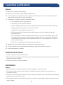
PATIENT POSITIONING AND COMFORT
General Repositioning
Patients should be turned or repositioned based on their individually planned treatment schedule or per
facility policy. Support surfaces are not substitutes for turning/repositioning or functional weight shifts.
Hand Check Procedure:
A suitable way to verify that the patient is not bottoming out is to perform a hand check as described below:
1) Ensure that the patient is lying supine (on his/her back) in the middle of the mattress.
2) Place a hand with four (4) ngers stacked vertically beneath the air cell directly underneath the sacral region.
3) Ensure that the 4 ngers can slide with minimal resistance between the patients’ sacral region and the
lower portion of the mattress.
4) Adjust the comfort setting as needs.
5) Wait for the mattress to adjust to the selected range.
6) Revaluate with the hand check and adjust to patients’ comfort level.
OPERATION

14
Recommended Linen:
Drive DeVilbiss Healthcare bed support surfaces are designed to be used with appropriate linens. Deep
pocketed tted or at sheets are recommended. Multiple layering of linens or underpads beneath the
patient should be avoided, when possible, for the prevention and treatment of pressure injuries.
Incontinence
Moisture against the skin surface is an extrinsic risk factor for acquiring a pressure injury as it weakens
the skin tissue leading to maceration. To protect skin integrity, incontinence barrier pads may be used to
absorb excess moisture.
Warning
Specialty active and reactive support surfaces are designed to redistribute pressure and reduce shearing/
friction forces against the patients’skin. Patient migration is possible due to the nature of these products.
Always ensure the patient is positioned properly within the connes of the bed and specialty system.
Note
It is important to follow these procedures before using the system or between patient use.
Control Unit (14030XP)
Caution
DO NOT immerse or soak the control unit in any water or uids.
DO NOT spray any cleaning solution directly on the surface of the control unit.
DO NOT use a Phenolic based cleaning solution as this may cause damage to the case.
1) UNPLUG the control unit from its power source prior to cleaning.
2) Check for external damage and move the control unit to the cleaning area.
3) Place the control unit on a work surface and wipe the outside of the case with a clean cloth to remove
any dust or particles. Make sure all areas are clean (top and bottom, both sides).
4) Spray cloth with cleaning solution and clean faceplate and control unit casing. DO NOT allow excess
cleaning solution on faceplate or control panel. (If solution gets inside, damage will occur.)
a. quaternary ammonium solution may be used.
5) After the control unit is thoroughly cleaned and dried, proceed to plug in the control unit and test for normal
functioning.
6) Unplug the control unit and store with proper identication tag until needed for use.
7) Avoid long exposure to sunlight.
CLEANING & MAINTENANCE

15
CLEANING & MAINTENANCE
Mattress
8) Remove any soiled or used bedding.
9) Examine the mattress for visible soilage of bodily uids.
10) If no disinfection is required, brush off or wipe down all surfaces of the cover sheet with soap and
water before wetting with any liquid disinfectant.
11) If disinfection is required, follow the procedure below:
a. Use rubber gloves and eye protection.
b. Unzip the top cover from the mattress.
c. Prepare detergent/disinfectant solution (registered by the EPA recommended) according to
the preparation recommended for correct use-dilution.
d. 1:9 Bleach and water dilution may be used.
e. With the mattress fully deated, wipe down all surfaces around and in between the air cells,
including the cells.
f. Covers may be immersed and soaked in disinfectant for the required incubation period. After
pre-soaking, the cover may be rinsed through a regular cycle in a washer with no soap then
laundered with mild detergent (wash temperature 93°F/34°C, rinse temperature 78°F/26°C or
on the coldest setting).
g. Allow all covers and parts to aerate until they are fully dry.
12) Repeat the process with the tubing set: spray/wipe, incubate, and air dry.
13) Dry the mattress on a at surface area after cleaning, away from exposure to the sun.
14) Avoid long exposure to sunlight.
HANDLING AND STORAGE
• Lay the mattress out at and upside down.
• Roll from the foot end towards the head end; the foot-end strap can then be stretched around the rolled
mattress to prevent unrolling.
• Do not fold, crease or stack the mattress.
MAINTENANCE
General
• Check the power cord and plug to see if there are abrasions or excessive wear.
• Check the mattress cover for signs of wear or damage. Ensure the mattress cover and tubes are
connected correctly.
• Plug in the control unit and check the airow from the hose connection port. The airow should alternate
between ports every half-cycle time.
• Check the air hoses to see if there are any kinks or breaks. For replacement, please contact your local
agent or dealer.

16
• Make sure the mattress tube is well connected.
• Check the control unit and make sure both power indicators are off when the switch is turned off.
Low pressure
Examine if there is any air leakage between the control unit and the mattress connections or from the air mattress tubes:
1) Check connectors between the air mattress and control unit. If there is any disconnection, please reconnect it.
2) Check the CPR Valves. Ensure their outlets are sealed.
3) Check the air-connecting tubes. Ensure each single cell is properly functioning.
4) Set the pressure at Auto Firm. Keep the tubes fully inated and inspect for air leakage.
5) Check if there is any air leakage from cells. Ensure no leakage occurs. If any leakage occurs, please
contact your local agent or dealer.
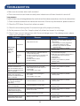
Problems Reasons Maintenance
Mattress fails
to inflate or
does not
inflate com-
pletely.
Pump issue
1. Pump does not work.
1. After powered on, check if visible LED
light turns on. If not, please check the
below issues:
1.1 Check if power cord is plugged into
appropriate voltage AC outlet.
1.2 Contact your provider for possible
warranty claim.
2. Air pressure from pump is too low.
1. Contact your provider for possible
warranty claim.
Mattress
issue
1. Quick connector on mattress does not
connect well with pump.
2. Air tube connected to T/L connector and
air valve is loose, CPR connector is
not capped.
3. One way valve is broken.
4. Air cell is leaking.
1. Make sure quick connector on mattress is
connected well with pump.
2. Make sure T/L connector and air valve is
connected well, CPR connector is
capped well.
3. Change air cell.
4. Contact your provider for possible
warranty claim.
Mattress has pillow function,
but air cells fail to inflate.
1. One way valve is assembled reversely. 1. Assemble the one way valve in correct
direction.
Pump is working but syn-
chronous motor does not
work; thus mattress does not
alternate, and alternate failure
alarm is activated.
1. Synchronous motor is out of order.
2. Wires inside synchronous motor not
connect well.
3. Lower PCB is out of order.
1. Contact your provider for possible
warranty claim.
Pump and motor keep
working, but cycle time is
incorrect. The alternate failure
alarm is activated.
1. Micro switch on the exchanger is
out of order.
2. Lower PCB is out of order.
1. Contact your provider for possible
warranty claim.
When powered on, compres-
sor stop after working some
time; but the exchanger
keep rotary.
1. Pressure detector is out of order.
1. Contact your provider for possible
warranty claim.
Mattress pressure is low but
alarm is not activated.
1. Pressure detector is out of order.
1. Contact your provider for possible
warranty claim.
Push button on panel is not
operated well, and LED
indicator does not light up.
1. Push button is not operated well.
2. LED is out of order.
1. Contact your provider for possible
warranty claim.
Mattress pressure is too high
or too low.
1. Pressure sensor is out of order.
1. Contact your provider for possible
warranty claim.
Power failure alarm can’t be
activated after power failure.
1. Battery is out of order.
1. Contact your provider for possible
warranty claim.
TROUBLESHOOTING

17
Control Unit
Item: 14030XP
Power supply: 120V/60Hz
Air output: 12 liter/min
Pressure range: 20-60 mmHg
Cycle time: 15/20/25/30 min.
Case Material: Flame Retardant ABS
Information Signal: Low pressure
Alternate/Static Mode
Size: 14.5”(L) x 5”(W) x 10”(H)
Weight: 10 lbs
FUSE: 1A 250V
Note
The above specications are also applicable to those areas operating with the same power supply range.
The Med Aire Plus 10” Mattress Replacement system has been tested and certied for the following
standards:
• UL
• c-UL
• UL 60601-1
• CAN/CSA C22.2 No. 601.1
• IEC60601-1-11
Y.Sung Handelvertretung
Duesselthaler St. 24, 40211 Duesseldorf,
Deutschland, Germany
SPECIFICATION
Mattress
Item: 14030MN, 14048MN, 14054MN, 14060MN
Size: 42” W x 80” L x 10” H (14030 model)
48” W x 80” L x 10” H (14048 model)
54” W x 80” L x 10” H (14054 model)
60” W x 80” L x 10” H (14060 model)
Top cover: Quilted Nylon / PU coating quilted stretch with zipper
Air cells: Nylon / PU Lamination
Base: 800D Nylon/PVC
Quantity & Height of Air Cells: 20 EA x 10” air cells:
- Cell on Cell Design prevents “bottoming out” and provides
up to 24 hours of power outage protection
- CPR valve for emergency procedures
- Pillow function and low air loss
- Quick connectors
Maximum Weight Capacity: 600 lbs (14030), 750 lbs. (14048),
1,000 lbs. (14054 & 14060)

18
14030|14048|14054|14060:18monthsforcontrolunitandmattress
Your Drive brand product is warranted to be free of defects in materials and workmanship for 18 months of
the original consumer purchaser.
This device was built to exacting standards and carefully inspected prior to shipment. This 18 month Limited
Warranty is an expression of our condence in the materials and workmanship of our products and our
assurance to the consumer of years of dependable service. This warranty does not cover device failure
due to owner misuse or negligence, or normal wear and tear. The warranty does not extend to non-durable
components, such as rubber accessories, casters, and grips, which are subject to normal wear and need
periodic replacement. If you have a question about your Drive device or this warranty, please contact an
authorized Drive dealer.
WARRANTY

19

99 Seaview Boulevard
Port Washington, NY 11050
Phone: 516-998-4600
Fax: 516-998-4601
www.drivemedical.com
VER.B.12.20
-
 1
1
-
 2
2
-
 3
3
-
 4
4
-
 5
5
-
 6
6
-
 7
7
-
 8
8
-
 9
9
-
 10
10
-
 11
11
-
 12
12
-
 13
13
-
 14
14
-
 15
15
-
 16
16
-
 17
17
-
 18
18
-
 19
19
-
 20
20


Drive Med Aire Plus 10" User manual
- Type
- User manual
- This manual is also suitable for
Ask a question and I''ll find the answer in the document
Finding information in a document is now easier with AI
Related papers
-
Drive LS9500N 10 Lateral Rotation Mattress Low Air Loss User manual
-
Drive 14360-P User manual
-
-
Drive Medical 14530 Owner's manual
-
Drive Medical 14048 Owner's manual
-
-
Drive DRV-14025N Operating instructions
-
Drive Medical 15030BV-PKG-1 Owner's manual
-
-
Other documents
-
Invacare SoftCloud Ace User manual
-
Apex Digital Pro-care Auto User manual
-
 Beautyrest 700753694-1030 User guide
-
Drive Medical Med-Aire 5" Alternating Pressure and Low Air Loss Overlay System Owner's manual
-
-
Port Designs 140103 Datasheet
-
 Beautyrest HDDOD7112DB Operating instructions
-
-
-
 Ultimate Healthcare UPRA3478D-2 Tamora II Digital Dynamic Mattress Overlay System User manual


