Page is loading ...

CONCRETE SAW
OPERATOR’S
MANUAL
MODELS
CC6571 and CC6571-3
September 9, 2015
Part # 1804004

CC6571 - CC6571-3 Concrete Saw Manual
Table of Contents
Safety Precautions .......................................................... 4
Safety Alerts ................................................................ 4
Proposition 65 ............................................................. 4
Spark Arrester Requirement ....................................... 4
Respiratory Hazards ................................................... 4
General Safety ............................................................ 5
Battery and Electrical Safety ....................................... 6
Blade Safety ................................................................ 6
Blade Guard Safety..................................................... 6
Fuel Safety .................................................................. 7
Engine Safety .............................................................. 7
Cutting Safety ............................................................. 8
Hydraulic Safety .......................................................... 8
Belt Safety ................................................................... 8
Transmission Safety ................................................... 8
Transporting Safety..................................................... 8
Lifting Safety ............................................................... 9
Introducing the CC6571 ................................................ 10
Components .............................................................. 10
Introducing the CC6571-3 ............................................. 11
Components .............................................................. 11
Controls ......................................................................... 12
Dimensions .................................................................... 13
Specifications ................................................................ 14
Operating the CC6571 and CC6571-3 .......................... 15
Handlebars ................................................................ 15
Adjusting the Handlebars ..................................... 15
Front Pointer ............................................................. 15
Adjusting the Front Pointer ................................... 15
Rear Pointers ............................................................ 16
Adjusting the Rear Pointers .................................. 16
Battery ....................................................................... 16
Diamond Blades ........................................................ 16
Inspecting the Blade ............................................. 16
Blade Speed ......................................................... 17
Installing the Blade ............................................... 17
Removing the Blade ............................................. 19
Blade Guard .............................................................. 20
Installing the Blade Guard .................................... 20
Removing the Blade Guard .................................. 20
Flange Guard ............................................................ 20
Installing the Flange Guard .................................. 20
Removing the Flange Guard ................................ 21
Water Supply ............................................................ 21
Using the Water Supply ........................................ 21
Water Safety Switch ............................................. 21
Water Pump .......................................................... 22
Control Grip ............................................................... 22
Raising the Saw .................................................... 22
Lowering the Saw ................................................. 22
Lowering Speed .................................................... 22
Speed Control Lever ................................................. 22
Forward Control .................................................... 22
Reverse Control .................................................... 23
Neutral Control ..................................................... 23
Transmission ............................................................ 23
Engaging the Transmission.................................. 23
Disengaging the Transmission ............................. 23
Shifting Three Speed Transmission ..................... 23
Fuel System .............................................................. 23
Adding Fuel .......................................................... 24
Cold Weather Fuel ............................................... 24
Storage ................................................................. 24
Display Panel ................................................................ 24
Soft Keys (Buttons) ................................................... 25
Status Icons .............................................................. 26
Main Menu ................................................................ 27
Arrow .................................................................... 27
DPF Commands ................................................... 27
Main Menu Action Items ........................................... 28
Gauges ................................................................. 29
Diagnostics ........................................................... 29
System Information .............................................. 30
Lamp Information ................................................. 30
User Settings ........................................................ 31
Automatic Shutdown ................................................. 32
Regeneration ............................................................ 32
Parked Regeneration Ready ................................ 32
Regeneration Message Levels ............................ 35
Engine ...................................................................... 36
Ignition Switch ...................................................... 36
Starting the Engine ............................................... 36
Stopping the Engine ............................................. 37
Concrete Cutting ....................................................... 37
Helpful Hints Prior to Cutting ................................ 37
Tasks Prior to Cutting ........................................... 37
Making a Cut ........................................................ 38
Adjusting the Depth Stop ..................................... 38
Continuing a Partial-Cut ....................................... 38
Finishing a Cut ..................................................... 38
Lighting ..................................................................... 38
Spot Light ............................................................. 38
Parking Brake ........................................................... 38
Engaging the Parking Brake ................................ 39
Disengaging the Parking Brake ........................... 39
Maintaining the CC6571 and CC6571-3 ....................... 40
Maintenance Overview ............................................. 40
Daily and/or Regularly .......................................... 40
50 Hours ............................................................... 40
500 Hours ............................................................. 40
Handlebars ............................................................... 40
Part Lubrication ........................................................ 40
Front Axle ............................................................. 40
Rear Axle.............................................................. 41
PTO ...................................................................... 41
Inner Blade Flange ................................................... 41
Installing the Inner Blade Flange ......................... 41
Removing the Inner Blade Flange ....................... 41
Rear Wheels ............................................................. 41
Battery ...................................................................... 41

CC6571 - CC6571-3 Concrete Saw Manual
Battery Type ......................................................... 41
Servicing the Battery ............................................ 42
Electrical System ...................................................... 42
Fuse Panel ........................................................... 42
Relays and Circuit Breakers ................................. 42
Magnetic Sensor ....................................................... 43
Adjusting the Magnetic Sensor ............................. 43
Replacing the Magnetic Sensor ........................... 43
Air Cleaner ................................................................ 43
Restriction Indicator .............................................. 44
Rubber Dust Ejector Boot ..................................... 44
Cleaning/Replacing the Outer Primary Filter ........ 44
Replacing the Inner Safety Filter .......................... 45
Speed Control Lever ................................................. 45
Adjusting the Speed Control Lever ....................... 45
Drive Alignment ......................................................... 46
Adjusting the Rear Drive....................................... 46
Oil Bath Blade Shaft /Oil Expansion Tank ................ 46
Changing the Oil - Single Speed .......................... 46
Changing Oil - Three Speed ................................. 47
Draining Heat Exchanger – Freezing Temps ....... 48
Hydraulic System ...................................................... 48
Adding Hydraulic Fluid.......................................... 48
Rear Drive Transmission .......................................... 49
Cooling Fan .......................................................... 49
Adding Oil ............................................................. 49
Adjusting the Rear Drive Chain ............................ 49
Belt System ............................................................... 49
Blade Drive Belts .................................................. 49
Belt Tension Setting ............................................. 49
Testing the Belt Tension ....................................... 49
Adjusting the Blade Drive Belts ............................ 50
Replacing the Blade Drive Belts ........................... 51
Primary Transmission V-Belt ................................ 52
Replacing the Primary Transmission V-Belt ......... 52
Secondary Transmission V-Belt ........................... 52
Replacing the Secondary Transmission V-Belt .... 52
Engine V-Belt ........................................................ 52
Rotary Tensioner ...................................................... 52
Adjusting the Rotary Tensioner ............................ 52
Replacing the Rotary Tensioner ........................... 53
Engine ....................................................................... 54
Engine Cooling System ........................................ 54
Radiator ................................................................ 54
Cooling Fan .......................................................... 54
In-Line Fuel Filter .................................................. 55
Oil and Fuel Lines ................................................. 55
Storing ....................................................................... 55
Disposal .................................................................... 55
References .................................................................... 56
Appendix A ................................................................ 56
Model and Serial Numbers ................................... 56
Appendix B ................................................................ 57
Daily Maintenance Task Chart ............................. 57
Appendix C ............................................................... 58
Troubleshooting .................................................... 58
Appendix D ............................................................... 60
Additional Resources ........................................... 60
Warranty………………………………………………..64

CC6
5
S
a
Ope
Con
c
acc
o
and
and
injur
pro
p
saw
s
invo
l
disc
o
liabl
e
Sa
w
Pro
d
Mod
not
t
all s
a
the
m
Ref
e
addi
t
ope
r
and
Seri
a
refe
r
The
at a
n
Saf
e
Se
r
ins
t
Se
r
the
Mil
d
the
5
71 - CC6571-
3
a
fety P
r
rate the CC
6
c
rete Saw a
o
rding to thi
s
understand
maintenanc
ies and/or d
p
erly trained
s
and shoul
d
l
ved. Impro
p
o
uraged an
d
e
for any re
s
w
modificatio
n
d
ucts to ens
u
ifications m
a
t
he responsi
a
w warranti
e
m
odification
.
e
r to the Dia
m
t
ional infor
m
r
ating the s
a
the engine’
s
a
l Tags sec
t
r
ence.
informatio
n
n
y time!
e
ty Alerts
DANGE
R
r
ious injurie
s
t
ructions ar
e
WARNI
N
r
ious injurie
s
se instructi
o
CAUTIO
N
d
and/or mo
se instructi
o
3
Concrete Sa
w
r
ecauti
6
571 Concr
e
nd all of the
s
manual. F
a
the followin
g
e instructio
n
eath. All op
e
or supervis
e
d
understan
d
p
er or unint
e
d
Diamond
P
s
ulting dam
a
n
s should b
e
u
re proper s
a
de to thes
e
bility of Dia
m
e
s if a probl
e
.
m
ond Prod
u
m
ation and p
a
a
w, record t
h
s
model and
t
ion in the In
n
in this m
a
R
s
and/or de
a
e
not followe
N
G
s
and/or de
a
o
ns are not f
o
N
derate injuri
o
ns are not f
o
w
Manual
ons
e
te Saw an
d
i
r
compone
n
a
ilure to co
m
g
safety, op
e
n
s can resul
t
e
rators mus
t
e
d prior to u
s
d
the risks a
e
nded saw u
P
roducts ca
n
a
ges.
e
made by
D
afety and a
c
e
saws by th
e
m
ond Produ
c
e
m arises a
s
u
cts’ Parts L
i
a
rt diagram
s
e saw’s ser
i
serial num
b
dex for futu
r
a
nual may
b
a
th will occu
r
d.
a
th could oc
c
o
llowed.
es could oc
c
o
llowed.
d
CC6571-3
n
ts
m
ply with
e
rations,
t
in serious
t
be
s
ing these
nd hazards
sage is
n
not be held
D
iamond
c
curacy.
e
owner are
c
ts and void
s
a result of
i
sts for
s
. Prior to
i
al numbe
r
,
b
e
r
s in the
r
e
b
e updated
r
if these
c
ur if
c
ur if
Pr
o
En
co
n
St
a
ca
n
re
p
Sp
a
In t
h
444
2
fore
s
lan
d
arre
effe
c
con
s
pre
v
Re
s
Co
kn
o
re
s
re
p
te
c
Fo
r
inf
o
Oc
A
d
In
s
(NI
o
position
6
WARNI
N
gine exhau
s
n
stituents a
r
a
te of Califo
r
n
cer, birth d
e
p
roductive h
a
a
rk Arrest
e
WARNIN
G
h
e State of
C
2
or 4443 t
o
st-covered,
d
unless the
e
ster, as defi
c
tive, worki
n
s
tructed, eq
u
v
ention of fir
s
piratory
H
WARNI
N
o
ncrete cutti
n
o
wn to caus
e
s
piratory dis
e
p
roductive h
a
c
hniques inc
Wearin
Wearin
shield.
Using
a
Washi
n
Using
w
minimi
z
Washi
n
eating/
d
r
additional
s
o
rmation co
n
c
cupational
S
ministration
s
titute for O
c
I
OSH).
6
5
N
G
s
t and some
r
e known to
r
nia to caus
e
e
fects, and/
o
a
rm.
e
r Require
m
G
C
alifornia it i
s
o
use or ope
r
brush-cove
r
engine is e
q
ned in Sect
i
n
g order or t
uipped, and
r
e pursuant
t
H
azards
N
G
n
g produce
s
e illness, d
e
e
ase, birth
d
a
rm. Safety
lude, but ar
e
g gloves.
g safety go
g
a
pproved re
s
n
g work clot
h
w
ater when
w
z
e dust.
n
g the hand
s
d
rinking.
s
afety and
s
n
tact your e
m
S
afety and
H
(OSHA), a
n
c
cupational
S
of its
the
e
o
r other
m
ent
s
a violation
r
ate the eng
r
ed, or gras
s
q
uipped wit
h
i
on 4442, m
a
he engine i
s
maintained
t
o Section 4
4
s
dusts and
f
e
ath, cancer
,
d
efects, and
/
protection
e
not limited
g
gles or a fa
s
pirators.
h
es daily.
w
et cutting
t
s
and face p
s
el
f
-protecti
o
m
ployer, th
e
H
ealth
n
d/or The N
a
S
afety and
H
of Section
ine on any
s
-covered
h
a spark
a
intained in
s
for the
4
43
f
umes
,
/
or other
to:
ce
t
o
rior to
o
n
e
a
tional
H
ealth
4

CC6
5
Ge
n
5
71 - CC6571-
3
n
eral Safet
y
Read an
d
operatio
n
provided
servicin
g
Keep sa
w
slurry, c
o
Inspect w
Clean, re
p
Raise th
e
height fo
working
u
saw. Us
e
the whe
e
frame e
d
frame fo
r
When u
s
the jack
a
frame b
a
while lifti
Repair t
h
problem
Replace
Dispose
accordin
g
regulatio
A
lways
h
the near
e
prior to
o
Operate
clothing.
A
lways
w
retaining
Persons
not oper
a
Keep all
machine
Replace
(unless
s
the saw.
A
lways
p
injuries.
DO NO
T
when in
N
the saw
o
prevent
u
All non-r
o
be perfo
r
center.
3
Concrete Sa
w
y
d
understan
n
s, and mai
n
in this man
u
g
the saw.
w
compone
n
o
ncrete dust
ater hoses p
r
p
air, or repla
c
e
saw to a p
r access w
h
u
nderneath
e
chocks to
b
e
ls, and fit bl
d
ges at the f
r
r
additional
s
s
ing a jack t
o
a
gainst a s
o
a
se to prope
r
ng.
h
e saw imm
e
arises.
saw decals
of all hazar
d
g
to city, st
a
ns.
h
ave a phon
e
e
st fire extin
o
perating th
e
the saw we
a
w
ear safety
g
rings.
under the s
t
a
te the saw.
body parts
a
r
y.
all guards
a
s
tated other
w
p
ivot guards
T
assume th
e
N
eutral or
w
o
n a slope.
C
u
nnecessar
y
o
utine main
t
r
med by an
a
w
Manual
d all of the
s
n
tenance in
s
u
al prior to
o
n
ts clean an
d
, and debris
r
ior to operati
n
c
e damaged
c
roper
en
the
b
lock
ocks or jac
k
r
ont and ba
c
s
upport.
o
raise the s
a
o
lid, flat area
r
ly support t
h
e
diately wh
e
if unreadab
l
d
ous waste
m
a
te, and fed
e
e
nearby, a
n
guisher and
e
saw.
a
ring flame
r
g
lasses wh
e
t
atutory age
a
way from r
o
a
nd access
p
w
ise) prior t
o
fully to avoi
d
e
saw will re
w
hen parkin
g
C
hock the ti
r
y
movement
t
enance tas
k
a
uthorized
s
s
afety,
s
tructions
o
perating or
d
free of
.
n
g the saw.
c
omponents.
k
s under the
c
k o
f
the
a
w, place
under the
h
e saw
e
n a
l
e.
m
aterials
e
ral
n
d locate
first aid kit
r
esistant
e
n removing
limit should
o
tating
p
anels
o
ope
r
ating
d
serious
main still
g
/stopping
r
es to help
.
k
s should
s
ervice
DO
D
h
O
o
L
t
e
O
s
O
o
w
O
a
O
h
O
a
O
o
O
a
O
h
O
b
O
O
a
O
C
r
G
s
T
s
L
a
P
d
S
S
s
NOT:
D
rop equip
m
h
andling to
h
O
perate the
o
r fumes to
L
ift and car
r
t
hat are too
e
asily.
O
perate the
s
afety equi
p
O
perate or
s
o
r accessor
i
w
hich could
O
perate the
a
rea.
O
perate the
h
ave been
r
O
perate the
a
ssociated
w
O
perate the
o
r fumes to
O
perate the
a
rea or with
O
perate the
h
ave been
r
O
perate the
b
olts.
O
perate the
O
perate the
a
nd/or alco
h
O
perate the
C
ut concret
e
r
emoved.
G
rease the
s
s
tated othe
rw
T
ouch hot c
o
s
aw.
L
eave the s
a
a
nd the bla
d
P
lace the s
a
d
own.
S
ervice the
S
ervice the
s
tated othe
rw
m
ent, suppli
e
h
elp preven
t
saw aroun
d
prevent fire
s
r
y equipmen
heavy and/
o
saw withou
p
ment requi
r
s
ervice the
s
i
es that can
lead to seri
o
saw with a
n
saw until u
n
r
emoved fro
m
saw using
a
w
ith o
r
reco
m
saw aroun
d
prevent fire
s
saw with a
n
in the direct
saw until al
r
emoved fro
m
saw with lo
saw when i
saw under
h
ol.
saw on ste
e
e
with guar
d
s
aw with th
e
r
wise).
o
mponents
w
a
w unatten
d
d
e has stop
p
a
w into stor
a
saw until it
h
saw with th
e
r
wise).
e
s, tools, et
c
t
injuries.
d
combustib
l
s
/explosion
s
t, supplies,
t
o
r cannot b
e
t using the
a
r
ed for the
w
s
aw with clo
t
snag in the
o
us injuries
n
yone near
t
n
necessary
m
the work
a
a
ttachment
s
m
mended f
o
d
combustib
l
s
/explosion
s
n
yone near
t
line of the
b
l unnecess
a
m
the work
a
ose nuts, s
c
ll or fatigue
d
the influenc
e
e
p slopes.
d
s and acce
s
e
engine ru
n
w
hen opera
d
ed until the
p
ed spinnin
g
a
ge until it h
a
h
as cooled
d
e
engine ru
n
c
., when
l
e materials
s
.
t
ools, etc.,
e
lifted
a
ppropriate
w
ork task.
t
hing, hair,
machinery,
or death!
t
he work
materials
a
rea.
s
not
o
r the saw.
l
e materials
s
.
t
he work
b
lade.
a
ry material
s
a
rea.
c
rews, and
d
.
e
of drugs
s
s panels
n
ning (unles
s
ting the
engine is o
f
g
.
a
s cooled
d
own.
n
ning (unles
s
s
s
f
f
s
5

CC6
5
Bat
t
Bla
d
A
c
N
a
b
I
d
n
D
e
K
5
71 - CC6571-
3
t
ery and E
l
Ignitable
emitted
f
NOT ex
p
sparks o
Keep th
e
ventilate
d
Keep th
e
Use prot
e
and avoi
d
handling
/
Use a pr
o
battery s
A
lways
b
cables t
o
reconne
c
Regularl
y
clamps,
a
replace,
necessa
r
A
lways
k
from the
is discon
connecti
o
Immedia
eyes wit
h
Seek m
e
Disconn
e
saw co
m
Remove
for long
e
A
lways
u
prevent
f
d
e Safety
A
lways use
r
c
entered dia
N
ever use a
a
dequate w
a
b
lade.
nspect all b
l
d
amaged bl
a
n
ecessary.
D
O NOT ins
t
e
ngine/moto
K
eep all bo
d
3
Concrete Sa
w
l
ectrical S
a
explosive g
f
rom the bat
t
p
ose the bat
t
r
open flam
e
e
area arou
n
d
.
e
battery lev
e
e
ctive eyew
e
d
contact wi
/
servicing t
h
o
per batter
y
trength.
b
e sure to c
o
o
the proper
c
ting the ca
b
y
inspect th
e
a
nd termina
tighten and
r
y.
k
eep the bat
t
battery ter
m
nected to a
v
o
ns while s
e
t
ely rinse y
o
h
water if ex
e
dical attenti
o
e
ct the batt
e
m
ponents (u
n
the battery
w
e
r periods.
u
se the corr
e
f
ires.
r
einforced a
b
mond blad
e
wet cutting
a
ter supply t
o
l
ades prior t
o
a
des. Clean
t
all or remo
v
r running.
d
y parts awa
y
w
Manual
a
fety
ases are
t
ery. DO
t
ery to
e
s.
d the batter
y
e
l when han
e
ar or a fac
e
th the skin
w
e battery.
y
tester whe
n
o
nnect the b
a
terminal wh
b
les.
e
battery, ca
ls for dama
g
grease com
t
ery cable cl
m
inals when
v
oid accide
n
e
rvicing.
o
ur clothing,
posed to ba
t
o
n immedia
t
e
ry prior to s
e
n
less stated
w
hen storin
g
e
ct size fuse
b
rasive bla
d
s.
blade witho
u
o
properly l
u
o
usage an
d
dirty blade
s
v
e a blade
w
y
from rotati
y
well-
dling it.
e
shield,
w
hen
n
testing the
a
ttery
en
bles,
g
es. Clean,
ponents as
amps away
the battery
n
tal
skin, or
t
tery acid.
t
ely!
e
rvicing all
otherwise).
g
the saw
s (amps) to
d
es or steel-
u
t an
u
bricate the
d
discard
s
as
w
ith the
ng blades.
I
a
d
D
e
w
A
c
a
T
s
W
e
W
a
b
D
r
b
r
D
a
D
l
T
p
F
b
s
L
c
A
b
t
s
s
r
.
i
Bla
D
r
B
c
W
r
s
Inspect the
b
a
nd cleanlin
d
irty/damag
e
D
O NOT ex
e
lse to the
d
w
hen opera
t
A
lways use
c
orrect blad
e
a
nd the typ
e
T
he blade
m
s
haft and/o
r
W
ear glove
s
e
nvironmen
t
W
hen instal
a
rrow printe
b
lade shaft’
s
D
O NOT ex
c
r
ecommend
b
lade spee
d
r
esulting in
s
D
O NOT us
e
a
void harmi
n
D
O NOT us
e
l
ower spee
d
T
ighten the
p
roperly se
c
F
ailure to p
r
b
lade may
c
s
aw.
L
et the blad
e
c
utting (app
A
lways inst
a
b
lade drive
b
t
he blade si
z
s
heave req
u
s
upport. Co
n
r
unning the
.Refer to th
e
i
n the Parts
de Guard
S
D
O NOT op
r
aised or re
m
B
lade expo
s
c
utting.
W
hen pivoti
r
aise/lower i
s
erious inju
r
b
lade flang
e
n
ess. Clean
o
e
d compon
e
pose yours
e
d
irect line of
t
ing the sa
w
an appropri
a
e
type base
d
e
of material
m
ust always
r
outer flang
e
s
and be al
e
t
when han
d
ling the bla
d
d on the bl
a
s
rotation.
c
eed the bl
a
ed speed w
d
s can caus
e
s
erious inju
r
e
damaged
n
g yourself,
e
a blade fo
d
than the bl
a
blade shaft
c
ure the out
e
r
operly secu
c
ause parts
t
e
cool prior
licable mod
e
a
ll the corre
c
b
elts, and fl
a
z
e. Changin
u
ires assist
a
n
tact techni
c
saw
e
RPM Char
List for addi
S
afety
erate the s
a
m
oved.
s
ure should
ng the front
i
t cautiously
r
ies.
e
s for dama
g
o
r replace
e
nts immedi
a
e
lf or anyon
e
the blade
w
.
a
te size bla
d
d
on the cut
t
being cut.
fit snug on
t
e
.
e
rt to the sur
r
d
ling blades.
d
e, always p
a
de in the di
r
a
de’s maxi
m
hen cutting.
e
blade bre
a
r
ies and/or
d
blades whe
n
others, or t
h
r cutting tha
a
de shaft s
p
screw/nut a
s
e
r flange an
d
re the outer
t
o loosen or
to removal
w
e
ls).
c
t blade sha
f
a
nges when
g the blade
a
nce from te
c
c
al support
p
r
t posted on
tional infor
m
a
w with the
b
not exceed
of the blad
e
and slowly
t
g
es, wear,
a
tely.
e
d
e and the
t
ing task
t
he blade
r
ounding
.
oint the
r
ection of th
e
m
um
Excessive
a
kage,
d
eath!
n
cutting to
h
e saw.
t requires a
p
eed.
s
directed t
o
d
blade.
flange and
fall off the
w
hen dry
f
t sheave,
changing
shaft
c
hnical
p
rior to
the saw or
m
ation.
b
lade guard
180° while
e
guard,
t
o avoid
e
o
6

CC6
5
A
g
g
u
i
D
t
A
t
I
s
d
W
p
i
Fu
e
A
S
D
D
L
R
f
A
M
p
D
o
t
C
e
D
t
e
F
(
f
En
g
R
s
R
o
A
f
5
71 - CC6571-
3
A
lways pivo
t
g
uard 180°
(
g
uard does
n
u
nexpectedl
y
njuries.
D
O NOT ins
t
he engine r
u
A
lways use
a
he blade si
z
nspect the
b
s
tarting the
s
d
irty/damag
e
W
hen loweri
p
ivot it cauti
o
njuries.
e
l Safety
A
lways use
c
S
tore all fue
l
D
O NOT op
e
D
O NOT fu
e
L
et the engi
n
R
efer to the
f
uels.
A
lways use
a
M
ove the sa
w
p
rior to start
i
D
O NOT sm
o
pen flames
ank or work
C
lean up an
y
e
ngine.
D
rain the fu
e
he saw for l
o
e
ngine man
u
F
uel may se
(
applicable
m
f
uel tank ha
s
g
ine Safet
y
R
efer to the
s
ource for e
n
R
efer to the
o
il.
A
lways kno
w
f
or emergen
c
3
Concrete Sa
w
t
the front of
fully upwar
d
n
ot swing d
o
y
, causing s
t
all or remo
v
u
nning.
a
blade gua
r
z
e.
b
lade guard
s
aw. Clean
o
e
d compon
e
ng the front
o
usly and sl
o
c
aution whe
l
in appropri
a
e
rate the sa
w
e
l the saw wi
n
e cool prio
r
engine man
a
ppropriate
f
w
away fro
m
i
ng the engi
n
oke or expo
when filling
ing with fuel
y
spilled fue
e
l tank and f
u
o
nger perio
d
u
al for additi
e
p out from
m
odels) wh
e
s
been over
f
y
engine man
n
gine safety
engine man
w
how to tur
n
c
y purpose
s
w
Manual
the blade
d
) so the
o
wn
erious
v
e the blade
r
d that corr
e
and water t
u
o
r replace
nts immedi
a
part of the
b
o
wly to avoi
d
n refueling.
a
te safety c
o
w
with a fue
th the engin
r
to adding f
u
ual for reco
m
f
uels in cold
m
the refueli
n
n
e.
se fuel to
the fuel
.
l prior to sta
u
el lines wh
e
d
s of time.
R
onal recom
m
the fuel ca
p
e
n raising th
e
f
illed.
ual as the p
.
ual for reco
m
n
off the en
g
s
.
guard with
e
sponds wit
h
u
bes prior t
o
a
tely.
b
lade guard,
d
serious
o
ntainers.
l leak.
e running.
u
el.
m
mended
weather.
n
g area
rting the
e
n storing
R
efer to the
m
endations.
p
vent
e
saw if the
rimary
m
mended
g
ine quickly
h
o
M
m
F
s
K
r
r
D
i
D
w
I
t
D
u
A
v
e
c
D
m
D
e
s
D
w
c
s
H
W
g
o
p
L
r
(
C
p
D
f
f
p
e
m
h
M
ake sure t
m
odels) is
a
F
ill the fuel
t
s
tarting the
e
K
eep all bo
d
r
otating par
t
r
unning.
D
O NOT st
a
i
nstalled.
D
O NOT all
o
w
hen cleani
Immediatel
y
t
hat may all
o
D
O NOT le
a
u
nattended.
A
lways ope
r
v
entilated a
r
e
ngine exh
a
c
onsciousn
e
D
O NOT op
m
aterials or
D
O NOT le
a
e
ngine is of
f
s
pinning.
D
O NOT to
u
w
ith the en
g
c
ool down
p
s
aw.
H
andle hot
o
W
ipe down
t
g
uards dail
y
o
perating te
DO NOT s
p
p
revent eng
L
et the engi
r
emoving p
r
(
applicable
m
C
lean the e
n
p
revent hig
h
D
O NOT us
e
f
luids (e.g.,
s
f
ilter) when
s
p
lug (applic
a
e
xtremely fl
a
m
elt parts o
h
elp start th
e
he speed c
o
a
t Neutral w
h
t
ank and ch
e
e
ngine.
d
y parts aw
a
t
s with the e
n
a
rt the engin
o
w dust to
e
ng/replacin
g
y
r
eplace da
m
o
w dust to
e
a
ve the engi
n
r
ate the sa
w
r
eas. Conc
e
a
ust can ca
u
e
ss and/or d
erate the s
a
fumes to p
r
a
ve the saw
f
and the bl
a
u
ch the engi
g
ine running
,
p
rior to touc
h
o
il carefully
w
t
he engine/
m
y
or regularl
y
mperatures
.
p
ray the eng
ine/motor d
a
ne cool prio
r
essurized c
a
m
odels).
n
gine coolin
h
operating
t
e
any starte
s
tarter fluid
s
s
tarting the
e
a
ble model
s
a
mmable a
n
r possibly e
x
e
engine.
o
ntrol lever (
h
en starting
e
ck the oil l
e
a
y from
ngine
e without th
e
e
nter the air
g
air filter(s).
m
aged saw
e
nter the en
g
ne/motor ru
n
w
in well-
e
ntrated
u
se loss of
eath.
a
w around c
o
r
event fires/
e
unattended
a
de has sto
p
ne/muffler
a
,
and alway
s
h
ing or servi
c
w
hen chan
g
m
otor exteri
o
y
to prevent
.
ine/motor
w
a
mage.
r
to
a
ps
g system re
g
t
emperature
s
r substance
s
s
prayed int
o
e
ngine usin
g
s
). These m
a
n
d explosive
x
plode whe
n
applicable
the engine.
e
vel prior to
e air filter(s
)
intake tube
component
s
g
ine.
n
ning
o
mbustible
e
xplosions.
until the
p
ped
a
ssembly
s
let them
c
ing the
g
ing the oil.
o
r and
high
w
ith water to
g
ularly to
s
.
s
or starter
o
the air
g
a glow
a
terials are
, and can
n
used to
s
7

CC6
5
Cut
t
T
o
c
w
T
t
D
a
t
s
D
o
c
D
i
s
u
Hy
d
Bel
t
5
71 - CC6571-
3
t
ing Safet
y
T
he direct w
o
r embedde
d
c
ould be da
m
w
hile cutting
T
urn off all
e
he direct w
o
D
O NOT ex
p
a
nyone else
he blade w
h
s
aw.
D
O NOT all
o
o
bject in an
d
c
utting.
D
O NOT as
s
n Neutral w
h
s
aw on a sl
o
u
nnecessar
y
d
raulic Sa
fe
Turn off
t
disconn
e
Lower th
hydrauli
c
saw.
A
lways
p
cardboa
r
against
h
compon
e
detectio
n
leaks. K
e
and/or a
r
Pressuri
z
the skin,
medical
a
t
Safety
Turn off
t
down pri
o
Regularl
y
stress cr
a
immedia
t
A
lways
c
operatin
g
Over-ten
power ta
belts ma
y
and/or p
o
3
Concrete Sa
w
y
o
rk area sh
o
d
electrical,
m
aged and/
o
.
e
lectricity, g
a
o
rk area prio
p
ose yourse
to the direc
t
h
en operatin
o
w any pers
o
d
around th
e
s
ume the sa
w
h
en stoppin
g
o
pe. Chock
t
y
movement
e
ty
t
he engine
p
e
cting hydra
u
e saw com
p
c
fluid press
u
p
lace a piec
e
r
d or paper
u
h
ydraulic
e
nts, or use
n
fluid to ch
e
e
ep all body
r
eas that m
a
z
ed hydrauli
causing se
r
a
ttention im
m
t
he engine
a
o
r to servici
n
y
inspect th
e
a
cks, and/o
r
t
ely when d
a
c
heck belt al
g
the saw.
sioning the
ke-off (PTO
y
cause slip
o
or saw per
f
w
Manual
o
uld not con
gas, or wat
e
o
r cause pe
r
a
s, and wat
e
r to cutting.
lf or
t
line of
g the
o
n, animal,
a
work area
w
w
will remai
g
and/or par
t
he wheels
t
.
p
rior to servi
c
u
lic compon
p
letely to reli
u
re prior to
s
e
of
u
p
a leak
e
ck for hydr
a
parts away
a
y eject hyd
r
c fluid can
p
r
ious injurie
s
m
ediately.
a
nd let the b
e
n
g them.
e
belts for fr
a
r
breakage
a
a
maged.
ignment pri
o
belts may d
a
). Unde
r
-te
n
page, short
e
f
ormance.
tain buried
e
r lines that
r
sonal injury
e
r around
a
nd/or
w
hile
n still while
king the
t
o prevent
c
ing and/or
e
nts.
eve some
s
ervicing th
e
a
ulic fluid
from leaks
r
aulic fluid.
p
enetrate
s
. Seek
e
lts cool
a
ying,
a
nd replace
o
r to
a
mage the
n
sioning the
e
r belt life,
e
Tra
n
Cle
a
to p
r
Tra
n
Squeali
n
DO NO
T
sheave
t
nsmissio
n
a
n the trans
m
revent high
nsporting
Remov
e
saw.
Make s
u
working
the load
vehicle.
Close th
transpo
r
Drain th
e
distanc
e
Use he
a
weight
o
or unloa
Raise th
compon
e
ramps.
Use ext
r
guiding
t
ramps.
S
saw for
w
Slowly
b
ramp. A
v
the saw
Chock t
h
truck/tra
Turn off
loaded i
n
propelle
d
lever at
N
transmi
s
Engage
the truc
k
Refer to
(DOT) f
o
transpo
r
require
m
n
g belts indi
c
T
use old an
d
t
ogether.
n
Safety
m
ission fan
oil tempera
t
Safety
e
the blade
p
u
re the truck
/
condition a
n
. DO NOT t
o
e fuel shuto
r
ting.
e
fuel tank
w
e
s.
a
vy-duty ra
m
o
f the saw a
n
ding.
e saw to av
o
e
nts while
m
r
eme cautio
n
t
he saw up
a
S
lowly drive
/
w
ard down t
h
b
ack/pull the
v
oid standin
to avoid se
r
h
e wheels a
n
iler prior to
t
the engine/
m
n
to the truc
k
d
models, p
l
N
eutral and
s
sion prior t
o
the brake o
n
k
/trailer to h
e
the Depart
m
o
r additional
r
tation techn
m
ents.
c
ate loosen
e
d
new belts
and fan gu
a
t
ures.
p
rior to trans
/
trailer is in
g
n
d sufficient
o
w the saw
b
ff valve wh
e
w
hen transp
o
m
ps that will
s
n
d yourself
w
o
id damagi
n
m
oving up a
n
n
when
a
nd down
/
push the
h
e ramp.
saw in rev
e
g directly d
o
r
ious injurie
s
n
d secure t
h
t
ransporting
.
m
otor once
t
k
/trailer. For
l
ace the sp
e
engage the
o
turning off
n
ce the sa
w
e
lp secure.
m
ent of Tra
n
information
iques and t
r
e
ss.
on the sam
e
a
rd regularly
porting the
g
ood,
to transpor
t
b
ehind a
e
n
o
rting long
s
upport the
w
hen loadin
g
n
g
n
d down
e
rse up the
o
wnhill from
s
.
h
e saw in a
.
t
he saw is
sel
f
-
e
ed control
the engine.
w
is secure i
n
n
sportation
on proper
r
uck/trailer
e
g
n
8

CC6
5
Lift
i
Sec
u
chai
n
hois
t
DO
N
impr
o
5
71 - CC6571-
3
i
ng Safety
Move yo
u
away fro
hoisting
t
crushed.
u
re the appro
p
n
s to the saw
’
t
ing.
N
OT attempt
t
o
perly.
3
Concrete Sa
w
u
rself and a
m
the lifting
t
he saw to
p
p
riate hoistin
g
’
s designated
t
o lift the sa
w
w
Manual
ll others
area when
p
revent bein
g
g
cables, stra
lift points pri
o
w
irresponsibl
y
g
ps, and/or
o
r to
y
and/or
9

CC6
5
In
t
Co
m
5
71 - CC6571-
3
t
roduci
m
ponents
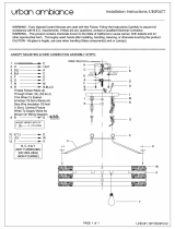
1.
F
2. I
3.
C
4.
C
5.
P
6.
W
7.
F
8.
B
9.
B
10.
D
11.
D
12.
A
13.
A
3
Concrete Sa
w
n
g the
F
rame Uprig
h
nstrument P
a
C
ontrol Leve
r
C
ontrol Grip
P
arking Brak
e
W
ater Suppl
y
F
uel Tank
B
attery
A
sse
m
B
reaker Pan
e
D
epth Indicat
o
D
epth Stop
As
A
ir Cleaner
A
ir Intake
w
Manual
CC657
h
t
a
nel
r
e
m
bly
e
l
o
r
s
sembly
1
Figure 1: Si
d
1
4
1
5
1
6
1
7
1
8
1
9
2
0
2
1
2
2
2
3
2
4
2
5
2
6
2
7
d
e Views of C
C
4
. ECU
5
. Lift Fram
e
6
. Frame B
a
7
. Rear Dri
v
8
. Eaton Tr
a
9
. Rear Axl
e
0
. Front Axl
e
1
. Front Wh
e
2
. Blade Sh
3
. Expansio
4
. Belt Ten
s
5
. Belt Gua
r
6
. Belt Driv
e
7
. Engine
C
6571
e
a
se
v
e Assembly
a
nsmission
e
e
e
el Assembly
aft
o
n Tank
s
ioner
r
d
e
Assembly
28. PTO
29. Rota
30. Tran
s
Jack
s
31. Exh
a
32. Radi
a
33. Cool
a
34. Radi
a
35. Dual
36. Blad
e
ry Tensioner
s
mission
s
haft
a
ust Pipe
ator
ant Tank
ator Shroud
Front Pointe
e
Guard
r
10

CC6
5
In
t
Co
m
5
71 - CC6571-
3
t
roduci
m
ponents
1. Fr
a
2. In
s
3. C
o
4. C
o
5. P
a
6. W
a
7. F
u
8. F
u
9. B
a
10. Br
e
11. D
e
12. D
e
13.
A
i
r
3
Concrete Sa
w
n
g the
a
me Upright
s
trument Pan
o
ntrol Lever
o
ntrol Grip
a
rking Brake
a
ter Supply
u
el Tank
u
el Cooler
a
ttery
A
ssem
b
e
aker Panel
e
pth Indicator
e
pth Stop
A
s
s
r
Cleaner
w
Manual
CC657
el
b
ly
s
embly
1-3
Figure 2: Sid
e
1
1
1
1
1
1
2
2
2
2
2
2
2
2
e
Views of C
C
4. Air Intake
5. ECU
6. Lift Fram
e
7. Frame Ba
8.
A
ccess D
o
9. Rear Driv
e
2
0. Eaton Tra
2
1. Rear Axle
2
2. Front Axl
e
3. Front Whe
e
2
4. 3 Speed
T
2
5. 3 Speed
B
2
6. Belt Guar
d
2
7. Belt Drive
C
6571-3
e
se
o
or
e
Assembly
nsmission
e
e
l Assembly
T
ransmission
B
lade Shaft
d
28. Engin
e
29. PTO
30. Rotar
y
31. Trans
m
Jacks
h
32. Exhau
33. Radia
t
34. Coola
n
35. Radia
t
36. Dual
F
37. Blade
e
Assembly
y
Tensioner
m
ission
h
aft
st Pipe
t
or
n
t Tank
t
or Shroud
F
ront Pointer
Guard
11

CC6
5
C
o
1
2
3
4
5
6
7
8
9
1
1
1
1
1
1
1
1
1
1
2
5
71 - CC6571-
3
o
ntrols
1
. Ignition
2
. Engine
T
3
. Engine
D
regener
a
4
. Parking
5
. Air Clea
6
. Depth S
t
7
. Cutting
8
. Pointer
R
9
. Water V
a
1
0. Emerge
n
1
1. Handle
L
1
2. Travel S
1
3. Raise P
u
1
4. Lower
P
1
5. Fuel Fill
e
1
6. Transmi
1
7. Water S
a
1
8. Spotlig
h
1
9. Water P
u
2
0. Lowerin
3
Concrete Sa
w
Switch–St
a
T
hrottle Ro
c
D
isplay Pa
n
a
tion, etc.
Brake Lev
e
n
er Restric
t
t
op Knob–
S
D
epth Indi
c
R
ope Cleat
–
a
lve–Contr
o
n
cy Stop B
u
L
ock Knob
s
peed Cont
r
u
shbutton
–
ushbutton
–
e
r / Gauge
C
ssion Eng
a
a
fety Switc
h
h
t Switch (
O
u
mp Switc
h
g Speed V
a
w
Manual
a
rts engine.
c
ke
r
–Incre
a
n
el – Displa
y
er
.
t
ion Indica
t
S
ecures cut
t
c
ato
r
–Indic
a
–
Secures fr
o
o
ls water flo
w
u
tton–Stop
s
s
–Secure h
a
r
ol Leve
r
–C
Raises saw
–
Lowers sa
w
C
ap–Openi
n
a
gement Le
v
h
(Optional
O
ptional Ite
m
h
(Optional
a
lve (Optio
n
Figure
a
ses and de
c
y
s specific e
t
or – Deter
m
t
ing depth.
a
tes blade’s
d
o
nt pointer
c
w
to blade.
s
engine.
a
ndlebars to
ontrols forw
and blade.
w
and blade
.
n
g to add fu
e
v
e
r
–Engag
e
Item)–Det
e
m
)–Powers
s
Item)–Pum
p
n
al Item) –
C
3: Saw Contr
o
c
reases eng
ngine infor
m
m
ines when
t
d
epth from
s
c
able.
frame uprig
ard/neutral/
r
.
e
l; indicates
e
s/disengag
e
e
cts an impr
o
s
potlight.
p
s water to
b
C
hanges sa
w
o
ls
ine speed/b
m
ation, spee
t
o service ai
s
urface.
g
ht.
r
everse mot
fuel level.
e
s transmis
s
o
per water
p
b
lade.
w
’s lowering
lade speed
d (RPM), fu
e
r cleaner.
ion of saw.
s
ion.
p
ressure.
speed.
(RPM).
e
l level, DP
F
F
12

CC6
5
D
5
71 - CC6571-
3
D
imens
i
3
Concrete Sa
w
i
ons
w
Manual
Figure 4: Si
d
d
e and Bott
o
o
m View
13

CC6571 - CC6571-3 Concrete Saw Manual
Specifications
Table 1: Saw Specifications
Maximum Cutting Depth 17-3/4” with 42” blade
Blade Shaft Diameter 2”
Arbor Diameter 1” with driven pin
Blade Shaft Bearings Oil Filled
Blade Shaft Drive 10 V-Belts
Blade Mounting Right or left
Blade Raise/Lower Electro-hydraulic pump
Blade Coolant Dual multi-spray water tubes
Blade Guard Attachment Slip-on up to 30”; bolt-on for 36” and 42”
Front Wheel Dimensions 8” × 3” × 1 5/8”
Rear Wheel Dimensions 10” × 3” × 2”
Handlebars Two-position tilt
Transmission Eaton model 10
Drive Speed 0-200 ft./min
Electric Start Standard
Hour Meter Standard
Amp Meter Warning light
Fuel Capacity Nine gallons
Tachometer Standard
Cutting Depth Indicator Standard
Quick Disconnect Blade Flanges Standard
Frame Lift Standard
Quick Release Rear Wheels Standard
Uncrated Weight
(add 100 lb. for crated weight)
1,844 – 1,901 lb.
Table 2: Engine/Motor Specifications
Manufacturer Kubota
Model V2607 Tier 4
H.P. (SAEJ1349) (HP / rpm) 2700 RPM
Fuel Type Ultra-low sulfur diesel fuel
Cylinders 4
Note: Refer to the engine manual for additional engine information and
specifications.
14

CC6
5
O
p
Ha
n
The
man
Ad
ju
1.
L
2.
H
h
h
t
w
o
l
e
3.
T
h
4.
R
h
5.
A
Fro
n
The
f
cutti
n
Ad
ju
1.
R
c
2.
L
3.
L
4.
D
5.
P
t
5
71 - CC6571-
3
p
eratin
g
n
dlebars
handlebars
euver the s
a
u
sting the H
a
L
oosen both
H
old the ha
n
h
andlebar in
h
andle lock
k
wo different
o
pening. Pl
a
e
ngth.
T
ighten the
h
h
andlebar.
Figure 5:
H
R
epeat step
s
h
andlebar.
A
djust the h
a
n
t Pointer
f
ront pointer
a
n
g line.
u
stin
g
the Fr
o
R
emove the
c
able cleat
o
L
ower the fr
o
L
oosen both
D
ivide an 8
–
P
lace the lo
o
he backsid
e
3
Concrete Sa
w
g
the
C
help the op
e
a
w.
a
ndlebars
handle loc
k
n
dleba
r
grip
to the handl
k
nob. The h
a
pathways i
n
a
ce the han
d
h
andle lock
k
H
andle Loc
k
s
2–3 to se
c
a
ndlebar le
n
a
ssembly hel
p
o
nt Pointer
tensioned
p
o
n the frame
o
nt pointer f
r
front point
e
–
10 ft. piece
o
ped end of
e
of the blad
e
w
Manual
C
C6571
e
rator guide
k
knobs.
and place t
h
ebar openi
n
a
ndlebar fit
s
n
side the ha
d
lebar at the
k
nob to sec
u
k
Knob and
H
c
ure the sec
o
n
gth as nec
e
p
s the opera
t
p
ointer lany
a
upright.
r
ame to the
e
r frame scr
e
of string in
h
string into
a
e
.
and C
C
and
h
e first
n
g below the
s
through
ndlebar
desired
u
re the
H
andlebar
o
nd
e
ssary.
t
or follow the
a
rd from the
floor.
e
ws.
h
alf.
a
gullet on
C
6571
-
6.
P
t
f
i
f
7.
c
8.
R
s
9.
L
t
10.
R
t
f
-
3
P
lace one s
t
t
he blade a
n
f
ront side of
i
n one hand
f
ront pointe
r
Figure
6
c
ap in betw
e
Figure 7:
R
etighten b
o
s
ecure the
p
L
ift the front
t
he cutting t
a
R
e-tension
t
t
he lanyard
f
ront pointe
r
t
ring line up
n
d one strin
g
f
the blade.
H
, tension th
e
r
rod.
6
: String Li
n
e
en the ten
s
Pointer C
a
Lin
e
o
th front poi
p
ointer rod.
t
pointer fra
m
a
sk is comp
t
he pointer l
a
into the cab
r
.
against the
g
line up ag
a
H
olding the
s
e
lines out t
o
n
e against
B
s
ioned strin
g
a
p between
e
s
nter frame
s
m
e off of the
lete.
a
nyard, and
le cleat to s
e
backside o
f
a
inst the
s
tring ends
o
ward the
B
lade
g
lines.
String
s
crews to
floo
r
when
then place
e
cure the
f
15

CC6
5
Re
a
The
Ad
ju
Loo
s
adju
poin
t
sec
u
Bat
t
Ign
em
ex
p
op
e
bat
Us
e
vol
t
str
e
Us
e
shi
e
ski
n
The
posi
t
cabl
e
5
71 - CC6571-
3
a
r Pointers
rear pointe
r
u
stin
g
the R
e
Fi
g
s
en the scre
st the rear
p
t
er up or do
w
u
re.
t
ery
WARNI
N
itable explo
s
itted from t
h
p
ose the bat
t
e
n flames, a
tery well-ve
n
CAUTIO
N
e
a proper b
t
meter, to te
e
ngth.
e
protective
e
ld, and av
o
n
when han
d
saw contai
n
t
ive battery
c
e
lead.
3
Concrete Sa
w
r
rods act as
e
ar Pointers
g
ure 8: Rear
P
w
on the ba
p
ointer rod’s
w
n, and the
n
N
G
s
ive gases
a
h
e battery. D
t
ery to spar
k
nd keep the
n
tilated.
N
attery teste
r
st the batte
r
eyewear or
o
id contact
w
d
ling a batt
e
n
s a charge
d
c
able lead
a
w
Manual
guides wh
e
P
ointer Rod
c
k of the fra
length and
t
n
retighten t
h
a
re
O NOT
k
s or
area aroun
d
r
, such as a
r
y
a face
w
ith the
ry.
d
battery wit
h
a
nd one neg
a
e
n cutting.
me edge to
t
o move the
h
e screw to
d
the
h
one
a
tive batter
y
y
Dia
m
D
O
ma
cut
t
ca
u
an
d
Usi
n
the
b
effi
c
ww
w
bla
d
Ins
p
Ins
p
all
d
mond Bla
d
WARNI
N
O
NOT excee
d
a
ximum reco
m
t
ting. Excessi
v
u
se blade br
e
d
/or death.
n
g the prop
e
blade and i
m
c
iency, resul
t
w
.diamondp
r
d
e types an
d
p
ectin
g
the
B
p
ect each bl
a
d
amaged bl
a
Cracks,
A dama
g
hole).
Darkne
s
blade.
A
defor
m
Segme
n
Core w
e
Bending
Uneven
d
es
N
G
d
the blade’s
m
mended sp
e
v
e blade spe
e
e
akage, resul
t
e
r blade (siz
e
m
proves cut
t
ting in lowe
r
r
oducts.co
m
d
additional
b
B
lad
e
a
de prior to
a
des. Inspe
c
nicks, and
d
g
ed and/or
d
s
s and/or di
s
m
ed blade c
i
n
t loss and/o
e
a
r
.
.
side-widths
.
e
ed when
e
ds can
t
ing in seriou
s
e
and type)
t
ing and op
e
r
costs. Ref
e
m
for a list of
b
lade infor
m
installation
a
c
t all blades
f
d
ents.
d
eformed ar
b
s
coloration n
i
rcumferenc
e
r segment
c
.
s
injuries
preserves
e
rato
r
e
r to
different
m
ation.
a
nd discard
f
o
r
:
b
or (center
ear edge o
f
e
.
c
racks.
16

CC6
5
Bla
d
Ref
e
blad
reco
NO
T
spe
e
req
u
sha
ft
Inst
a
D
O
en
g
Fai
fla
n
fall
W
e
en
v
5
71 - CC6571-
3
d
e Speed
e
r to the CC
6
e, or the bl
a
mmended
b
T
exceed th
e
e
d. DO NO
T
u
ires a lowe
r
ft
speed.
Fig
Figu
r
a
l
l
in
g
the Bl
a
WARNI
N
O
NOT instal
l
g
ine running
lure to prop
e
n
ge and bla
d
off of the s
a
CAUTIO
N
e
ar gloves a
n
v
ironment w
h
3
Concrete Sa
w
6
571 or CC
6
a
de packagi
n
b
lade speed
s
e
maximum
r
T
use a blad
r
speed than
ure 9: CC657
1
r
e 10: CC6571
a
d
e
N
G
l
a blade wit
.
e
rly secure
t
d
e may cau
s
a
w.
N
n
d be alert t
o
h
en handlin
g
w
Manual
6
571-3 RP
M
n
g informati
o
s
when cutti
n
r
ecommend
e
e for cutting
the minimu
1
RPM Chart
-3 RPM Char
t
h the
t
he outer
s
e parts to l
o
o
the surrou
g
blades.
M
Chart, the
o
n for the
n
g. DO
e
d blade
that
m blade
t
o
osen or
nding
Use
with
A
pp
tigh
t
sec
u
me
a
Inst
a
sa
w
tas
k
nec
e
she
a
cha
n
req
u
Co
n
sa
w
in t
h
info
r
Re
m
Left
1.
R
(
h
f
2.
L
f
T
e
the 15/16”
c
the saw w
h
p
ly force to t
h
t
en the bolt
t
u
re the oute
a
surement c
a
ll the blad
e
w
; utilize the
m
k
. Adjust the
e
ssary, and
a
ve, blade
d
n
ging the bl
a
u
ires assis
t
n
tact techn
i
w
. Refer to t
h
h
e Diamond
r
mation.
m
ove Mount
e
Side of Saw
w
R
emove th
e
(
attached to
h
inge knuc
k
f
langes.
Figure 1
L
ift up the f
r
f
ront hinge
k
T
his preven
t
c
ombinatio
n
h
en installin
g
h
e opposite
t
o 125 ft-lb
(
r flange an
d
an be verifi
e
Figure 11:
W
e
on either t
h
most appro
p
engine gov
e
install the a
d
rive belts,
a
a
de size. C
h
t
ance from
i
cal suppor
t
h
e RPM Ch
a
Products’ P
e
d Blade Gu
a
w
ith 26” to 42
”
e
blade guar
d
blade guar
d
k
le to gain a
c
2: Lock Pin t
h
r
ont half of t
h
k
nuckles co
n
t
s the front
h
n
wrench th
a
g
/removing
a
end of the
w
(
169.5 Nm)
t
d
blade. Thi
s
e
d with a tor
q
W
rench
h
e right or le
p
riate side f
o
e
rnor settin
g
ppropriate
b
a
nd flanges
w
h
anging th
e
technical s
t
prior to r
u
a
rt posted o
n
arts List for
a
rd
”
Guards
d
or insert l
o
d
) through t
h
c
cess to the
h
rough Rear
H
h
e blade gu
a
n
tact this lo
c
h
alf of the g
u
a
t comes
a
blade.
w
rench and
t
o properly
s
q
ue wrench
ft side of th
e
or
the cuttin
g
g
, as
b
lade shaft
w
hen
e
blade siz
e
upport.
u
nning the
n
the saw, o
r
additional
o
ck pin
h
e wide rea
r
blade
H
inge
a
rd until the
c
k pin. (Not
e
u
ard from
.
e
g
r
r
:
17

CC6
5
c
u
W
3.
S
r
i
t
Righ
t
Mou
n
1.
R
g
b
5
71 - CC6571-
3
c
ontacting t
h
u
sing secon
d
Figu
W
arning: Fr
o
secure
d
S
ecure front
r
ing of first l
o
nsert throu
g
he front 2 h
i
Figu
r
t
Side of Saw
n
ted Blade G
u
R
emove the
g
uard 180°
(
b
lade flange
3
Concrete Sa
w
h
e engine D
P
d
lock pin lo
c
re 13: Front
H
Contacts L
o
o
nt half of
b
d
in this u
p
half of blad
e
o
ck pin to all
g
h this ring
a
i
nge knuckl
e
r
e 14: Second
Ring
o
and Left Side
u
ards
blade guar
d
fully upwar
d
s
. Secure w
w
Manual
P
F canister.
c
ated on be
H
inge Knuckle
o
ck Pin
b
lade guard
right positi
e
guard by
p
ow second
l
nd continue
e
s.
Lock Pin thr
o
o
f First
(less than 26
”
d
or pivot th
e
d
) to gain ac
c
ith pin.
) Secure by
lt guard.
must be
on!
p
ositioning
l
ock pin to
on through
o
ugh
”
to 42”)
e
front of th
e
c
ess to the
e
Re
m
1.
R
T
t
(
2.
R
c
f
Figure
m
ove Outer
B
Figur
e
R
emove th
e
T
urn the bol
t
he right sid
e
(
right-hand
t
R
emove th
e
c
arefully pul
f
lange align
m
Figur
e
15: Blade Gu
B
lade Flange
e
16: Blade Fl
e
blade shaf
t
l
t clockwise
e
of the sa
w
t
hreads) on
e
bolt and w
e
l
l the outer f
l
m
ent pin ho
l
e
17: Blade Fl
a
ard Locking
P
e
anges Toget
h
t
bolt using
t
(left-hand t
h
w
, and count
e
the left side
e
dge lock w
a
l
ange out of
l
e and blad
e
a
nges Separa
t
P
in
h
e
r
t
he wrench.
h
reads) on
er
clockwise
of the saw.
a
sher, and
the inner
e
shaft.
t
ed
18

CC6
5
3. I
i
d
n
4.
S
a
5.
R
t
6.
P
p
d
i
7.
A
s
b
F
i
8.
S
b
b
9.
P
s
s
10.
T
a
t
11.
T
(
a
w
5
71 - CC6571-
3
nspect the
b
nner flange
d
amages an
n
ecessary.
S
elect the c
o
a
nd inspect
t
R
aise the s
a
he blade.
P
lace the bl
a
p
oint the arr
o
d
irection of t
nstalling th
e
A
lign and fit
s
haft throug
h
b
lade shaft
a
i
gure 18: In
s
S
lightly
r
ota
t
b
ackward to
b
etween pa
r
P
lace the w
e
s
haft bolt an
s
haft.
T
ighten the
b
a
nd slowly l
o
he ground’s
T
ighten the
b
(
169.5 Nm)
t
a
nd blade.
T
w
ith a torqu
e
3
Concrete Sa
w
b
olt, outer fl
a
alignment p
d clean, re
p
o
rrect blade
t
he blade fo
a
w slightly t
o
a
de next to
t
o
w printed
o
he blade sh
a
e
blade.
the outer fl
a
h
the blade
h
a
nd inner fla
s
erting the
O
t
e the outer
f
eliminate b
a
r
ts.
e
dge lock w
a
d
insert the
b
olt by hand
o
wer the bla
d
surface.
b
olt, using t
h
t
o properly
s
T
his measur
e
e
wrench.
w
Manual
a
nge, inner
f
in hole for v
air, or repla
c
type for the
r
visible da
m
provide ro
o
t
he inner fla
n
o
n the blade
a
ft’s rotatio
n
a
nge alignm
e
h
oles, and i
n
nge alignm
e
O
uter Flang
e
f
lange and
b
a
cklash (loo
s
a
sher onto t
h
bolt into the
as much a
s
d
e until it ju
s
h
e wrench, t
o
s
ecure the o
u
e
ment can
b
f
lange, and
isible
c
e or as
cutting tas
k
m
ages.
o
m to install
n
ge.
A
lways
in the
n
when
e
nt pin and
n
to the
e
nt pin hole.
e
b
lade
s
eness)
h
e blade
blade
s
possible,
s
t touches
o
125 ft-lb
u
ter flange
b
e verified
k
12.
R
t
Re
m
A
r
e
d
1.
R
g
g
2.
S
g
3.
R
w
4.
C
f
t
a
5.
I
i
d
n
6.
A
s
a
7.
P
s
s
8.
T
o
9.
R
t
Fig
R
eattach th
e
t
he guard d
o
m
ovin
g
the B
CAUTI
O
A
lways let th
e
e
moving or
r
ry cutting.
R
emove th
e
g
uard 180°
(
g
ain access
S
lowly lowe
r
g
round’s su
r
R
emove th
e
w
asher fro
m
C
arefully pu
f
lange align
m
t
hen remov
e
a
ppropriate
Inspect the
b
i
nner flange
d
amages a
n
n
ecessary.
A
lign and fit
s
haft into th
e
a
lignment p
i
P
lace the w
e
s
haft bolt a
n
s
haft.
T
ighten the
o
uter flange
R
eattach th
e
t
he guard d
o
ure 19: Tight
e
e
blade gua
r
o
wn and ov
e
B
lad
e
O
N
e
blade cool
r
eplacing bl
a
e
blade guar
d
(
fully upwar
d
to the blad
e
r the blade
u
r
face.
e
blade shaf
t
m
the blade
s
ll the outer
f
m
ent pin ho
l
e
the blade.
storage loc
a
b
olt, outer fl
a
alignment
p
n
d clean, re
p
the outer fl
a
e
blade sha
f
i
n hole.
e
dge lock w
n
d insert the
bolt by han
d
together.
e
blade gua
r
o
wn and ov
e
e
ning the Bolt
r
d or pivot t
h
e
r the blade
prior to
a
des when
d
or pivot th
e
d
, secure wi
t
e
flanges.
u
ntil it just t
o
t
bolt and w
e
s
haft.
f
lange out o
f
l
e and blad
e
Place the b
l
a
tion.
a
nge, inner
p
in hole for
v
p
air, or repl
a
a
nge alignm
f
t and inner
f
asher onto
t
bolt into th
e
d
to secure
t
r
d or pivot t
h
e
r the blade
h
e front of
to secure.
e front of th
e
th pin) to
o
uches the
e
dge lock
f
the inner
e
shaft, and
l
ade in the
flange, and
v
isible
a
ce as
ent pin and
f
lange
t
he blade
e
blade
t
he inner an
d
h
e front of
to secure.
e
d
19

CC6
5
Bla
d
DO
rai
s
DO
run
n
Bla
d
18
0
A
l
w
up
w
swi
n
The
be i
n
a gu
Inst
a
1.
R
f
a
2.
P
b
m
3. I
i
4.
F
g
s
g
t
5
71 - CC6571-
3
d
e Guard
WARNI
N
NOT operat
e
s
ed or remov
e
NOT remov
e
n
ing.
d
e exposure
w
0
°.
w
ays pivot the
w
ard) and se
c
n
g down une
x
blade guar
d
n
place whe
n
ard that ma
t
a
l
l
in
g
the Bl
a
R
egularly in
s
f
or cuts, slur
a
wire brush
P
lace the ta
p
b
lade guard
m
ount on th
e
Fig
u
nsert the lo
c
nto the tape
F
or the 36-4
g
uard cap s
c
s
ide (facing
a
g
uard, and t
h
hreaded ho
l
3
Concrete Sa
w
N
G
e
the saw wit
h
e
d.
e
the blade g
u
w
hen cutting
front of the
b
c
ure with pin
s
x
pectedly, ca
d
shields the
n
operating
t
t
ches the bl
a
a
de Guard
s
pect the bl
a
ry, and/or d
e
or replace
t
p
ered moun
t
down onto
t
e
frame bas
e
u
re 20: Loweri
c
k pin, conn
e
red blade g
u
2
” blade gu
a
c
rew throug
h
a
way from t
h
h
en tighten
t
l
e on the sid
w
Manual
h
the blade g
u
u
ard with the
should not e
x
b
lade guard 1
8
s
o the guard
d
using seriou
s
blade and
m
t
he saw. Be
a
de size.
a
de guard w
e
bris. Clean
t
he tubes as
t
from one s
t
he tapered
b
e
.
ng the Guard
e
cted to the
u
ard mount
a
rds; place
t
h
the hole o
n
h
e saw) of t
h
t
he screw in
e of the fra
m
u
ard
engine
x
ceed
8
0° (fully
d
oes not
s
injuries.
m
ust alway
s
sure to use
ater tubes
them using
necessary.
ide of the
b
lade guard
lanyard,
hole.
he blade
n
the rear
h
e blade
to the
m
e base.
s
5.
C
t
g
Re
m
1.
D
b
2.
R
g
3.
F
g
s
g
4.
U
g
o
Fla
n
Inst
a
1
Figur
e
C
onnect on
e
t
he water v
a
g
uard hose
Figur
e
m
o
v
in
g
the B
D
isconnect
t
b
lade guard
R
emove th
e
g
uard moun
F
or the 36-
4
g
uard cap s
c
s
ide of the f
r
g
uard.
U
se the ha
n
g
uard back
a
o
f the taper
e
n
ge Guar
d
a
l
l
in
g
the Fl
a
. Remov
e
guard m
e
21: Blade G
u
e
end of the
a
lve and the
fitting.
e
22: Blade G
u
B
lade Guard
t
he wate
r
s
u
hose fitting
e
lock pin fr
o
n
t hole.
4
2” blade gu
crew from t
h
r
ame base
a
n
dle on the
b
a
nd forth w
h
e
d blade gu
a
d
a
n
g
e Guard
e
the lock pi
n
ount hole.
u
ard Cap Scr
e
water supp
l
other end t
o
u
ard Hose Fitt
i
u
pply hose f
r
.
o
m the taper
e
ard; remov
e
h
e threaded
a
nd from th
e
b
lade guard
t
h
ile lifting th
e
a
rd mount.
n
from the t
a
e
w Hole
l
y hose to
o
the blade
i
ng
r
om the
e
d blade
e
the blade
hole on the
e
blade
t
o rock the
e
guard off
a
pered blad
e
e
20
/