Page is loading ...

RFP Inst -Warn (Rev. 02/11/19) Page 1 of 14
P/N 230418
BUCKINGHAM MFG.
P/N’s RFPDELUXE; RFPBASIC; RFPREDIRECT
Instructions / Warnings
The Buckingham P/N RFPBASIC, P/N RFPREDIRECT and Patent Pending P/N RFPDELUXE (consists of P/N RFPBASIC [Fig. 1] and P/N
RFPREDIRECT [Fig. 2]) provides a temporary system that allows the user to set a lifeline and Re-Direct lines from the ground to keep
them 100% Fall Protected while ascending a ladder, working on the ladder or elevated surface and descending the ladder.
Note: hardware / material colors and or lengths may vary from that shown.
Fig. 1
Fig. 2

RFP Inst -Warn (Rev. 02/11/19) Page 2 of 14
P/N 230418
Review of Job Site
1. Observe and inspect the work area.
2. Determine installation location and locate suitable anchors (anchors need to be located on the opposite side of the
structure from the work being performed).
3. Determine Application needed.
a. Basic Application (Pages 3 - 6) (P/N RFPBASIC)
• Work area is easily reached from ladder or minimal access to the roof is required
• No chance of a swing fall
b. Re-Direct Application (Pages 6 - 12) (P/N RFPDELUXE)
• Work area is close to a peak or edge
• Chance of swing fall
• Chance of lifeline sliding off peak or edge
c. Load Sharing Application (Pages 6 - 12) (P/N RFPDELUXE)
• Questionable anchorage. Must share the load between multiple anchors.
• Set-up the same as Re-Direct Application (‘b’ above)
d. Load Sharing / Re-Direct Application (Pages 6 - 12) (P/N RFPDELUXE)
• Questionable anchorage. Must share the load between multiple anchors.
• Work area is close to a peak or edge
• Chance of swing fall
• Chance of lifeline sliding off peak or edge
• Set-up the same as Re-Direct Application (‘b’ above)
4. Suitable Anchorages:
▪ Trees
Trees may be used as a suitable anchor when the following criteria is met:
• Healthy, with no signs of rot or decay.
• Minimum of 6” diameter trunk (measured 6” up from the ground).
• Stable ground.
• Packed / compressed soil (avoid loose soil).
• Always keep anchor point at ground level.
• Work practice is approved by employer.
▪ Vehicle
Vehicles may be used as a suitable anchor when the following criteria is met:
• Has a minimum weight of 4,000 lbs.
• Is in good repair.
• Keys have been removed from ignition and vehicle has been locked out.
• Has at least a Class III hitch and the user ONLY connects to the hitch or similarly rated tow hooks.
• Is parked on a stable and level surface.
• Has parking brake engaged.
• Work practice is approved by employer.
▪ Utility Pole
Utility poles may be used as a suitable anchor when the following criteria is met:
• Well maintained pole that is free of rot and decay.
• Minimum 30, class 4 pole.
• Pole is straight (avoid crooked and leaning poles).
• Stable ground.
• Packed / compressed soil (avoid loose soil)
• Always keep anchor point at ground level.
• Work practice is approved by employer.

RFP Inst -Warn (Rev. 02/11/19) Page 3 of 14
P/N 230418
A. Installing the P/N 39Y11Q2-150 Lifeline (Basic Application – see Fig. 1 for components):
1. Determine ladder placement to reach the work area.
2. Ensure the area behind the structure is clear of objects, persons, animals or anything that the throw bag could contact /
damage / injure.
3. Ensure the path of the throw bag and line are clear of any powerlines, phone line or other utility cables and wires.
4. Follow the BuckLaunch product instructions and launch the throw bag with throw line attached over the structure and
towards the anchor or the work area (Fig. 3). When launching the throw bag ensure the path and area where the throw bag
will land is clear as noted in steps 2 and 3 above.
5. Attach the end of the throw line to the anchor eye of the lifeline and pull over the structure towards the anchor
(Fig. 4 - 5). Note: If the BuckArrester is installed on the lifeline you must maintain the position of the BuckArrester so that
when you pull the lifeline over the structure it will remain where you can access it. If the BuckArrester is not installed on the
lifeline, follow Section E below.
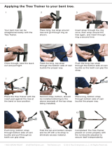
B. Installing P/N 3904J12-8 Lifeline Temporary Anchor Strap:
1. Choose a suitable fall arrest anchor point (see 4 under Review of Jobsite above). Anchor needs to be located such that when
the lifeline is installed the position of the anchor will keep the lifeline in the work area, away from any edges and prevent a
swing.
2. Wrap temporary anchor strap around suitable anchor (Fig. 6).
3. Insert the small D-ring through the larger D-ring (Fig. 7).
4. Pull end of strap with smaller D-ring through larger D-ring choking the strap around the anchor (Fig. 8).
Note: On a smaller diameter anchor, it may be necessary to wrap the strap around the anchor multiple times before
choking the strap (Fig. 9).
C. Attaching Lifeline to Temporary Anchor Strap:
1. Untie throw line from eye of lifeline (Fig. 10).
2. Attach P/N 5005 Carabiner to eye of lifeline (Fig. 11).
3. Connect the carabiner to the small D-ring on the temporary anchor strap (Fig. 12).
Fig. 3
Fig. 4
Fig. 5
Suitable
Anchor
Fig. 6
Fig. 7
Fig. 8
Fig. 9
Suitable
Anchor
Suitable
Anchor
Lifeline
Fig. 10
Fig. 11
Fig. 12
Lifeline
Throw
Line
Throw
Line
Work
Area
Large
D-Ring
Small D-Ring

RFP Inst -Warn (Rev. 02/11/19) Page 4 of 14
P/N 230418
D. Installing the RFP Lifeline Flag:
1. Open the hook & loop fastener strap located at the top of the flag (Fig. 13).
2. Wrap the hook & loop fastener strap around the previously installed lifeline or re-direct line and secure the hook & loop
fastener together (Fig. 14). Note: Install the RFP lifeline flag in a location that is close to the anchor point and easily seen.
E. Installing the Ladder:
1. Following the ladder manufacturer’s instructions and your employer’s work practices, install the ladder in the desired
location to reach the work area (Fig. 15). Note: The ladder must be installed at the proper angle (approx. 75.5° or 4:1 ratio)
with a minimum of 3’ (but less than 6’) extended past the roof line. Failure to properly install the ladder could result in
your serious injury or death.
F. Attaching the P/N 5004BQ1 BuckArrester Mobile Fall Arrester (MFA) to the Lifeline:
1. Ensure the UP arrow on the frame of the BuckArrester is facing the top of the ladder and up the lifeline (Fig. 16 - 17).
2. Rotate the cam up into the open position (Fig. 18).
3. Insert the tail of the lifeline through the top of the BuckArrester channel between the frame and the cam (Fig. 19 - 20).
4. Slide the BuckArrester into the desired position on the lifeline (Fig. 21).
Integral
Attachment
Carabiner
(Z359.12)
BuckArrester
Mobile Fall Arrester
(MFA)
UP Arrow
(Must Point to Anchor)
Cam Lever
Locking Nut
Integral Lanyard
(with impact load indicator)
(MFA)
Frame
Fig. 16
Fig. 15
Work
Area
Lifeline
Patent Pending
Hook & Loop
Fastener Strap
(open)
RFP Lifeline Flag
Fig. 13
Fig. 14

RFP Inst -Warn (Rev. 02/11/19) Page 5 of 14
P/N 230418
G. Securing the Tail of the Lifeline to the Ladder:
1. Pull the slack out of the lifeline (pulling away from anchor) and form a loop in the lifeline in front of the 2
nd
or 3
rd
rung (on
the bottom) on the ladder (Fig. 22).
2. Wrap the loop behind the rung (Fig. 23).
3. Bring loop around behind the doubled lifeline and back through the doubled loop formed (Fig. 24 - 25).
4. Pull knot tight (Fig. 26).
Note: Securing the lifeline to the ladder allows for the user to remove slack from the lifeline.
H. Attaching BuckArrester to Harness:
1. Open the Integral Attachment Carabiner gate (Fig. 27).
2. Connect the carabiner to the Harness Sternal D-ring (Fig. 28).
3. Ensure the carabiner gate is completely closed (Fig. 29).
0
Note: When ascending and descending the ladder the BuckArrester Mobile Fall Arrester (MFA) will freely follow the user up and
down the lifeline. If the BuckArrester should catch on the rope (the BuckArrester may catch on the lifeline prematurely if the user is
climbing too fast or if their body is too far away from the ladder) the user should stop and release the cam of the BuckArrester, (to
release, take the tension off of the lanyard and press the cam towards the body of the BuckArrester) reposition the BuckArrester
below your sternal connection and then continue descending down the ladder. Always Follow employer’s work practices and
maintain 3 points of contact while ascend and descending the ladder.
Top of the
Ladder / Lifeline
Fig. 17
Fig. 18
Fig. 19
Fig. 20
Fig. 21
Fig. 22
Fig. 23
Fig. 24
Fig. 25
Fig. 26
Fig. 27
Fig. 28
Fig. 29

RFP Inst -Warn (Rev. 02/11/19) Page 6 of 14
P/N 230418
Tip for descending:
Placing your hand in the center of the rung behind the lifeline will guide it away from the rung preventing the BuckArrest from
contacting the rung and accidentially engaging.
P/N RFPREDIRECT
I. Determining Attachment Point for Re-Direct Line
Note: The Re-Direct Application (Fig. 2) is used in conjunction with the Basic Application (Fig. 1)
1. Determine placement of the ladder to reach the work area.
2. Review the work area and determine if the lifeline will be near an edge or has the potential for a swing fall based on the
location of a suitable anchor for the lifeline (Fig. 33)
3. If the lifeline is near an edge or has the potential for a swing fall determine suitable attachment point(s) for the Re-Direct
line(s) that will keep lifeline from an edge and prevent a swing fall (Fig. 34). Note: It may be necessary to use multiple Re-
Direct lines
4. Once you have the determined position for the Re-Direct lines, estimate the approximate distance from the lifeline anchor
to the first position of a Re-Direct line attachment and install a P/N P9C6A-10-18 lifeline prusik in this location (see section I
below).
5. If a second Re-Direct line is needed, estimate the approximate distance from the lifeline anchor to the position of second
Re-Direct line attachment and install a P/N P9C6A-10-18 lifeline prusik in this location (see section I below).
Path of
Lifeline
Work
Area
Potential for Swing Fall
Fig. 33
Suitable
Lifeline
Anchor
Attachment
Point for
Re-Direct Line
Attachment
Point for
Re-Direct Line
Suitable
Lifeline
Anchor
Fig. 34
Fig. 30
Fig. 31
Fig. 32

RFP Inst -Warn (Rev. 02/11/19) Page 7 of 14
P/N 230418
J. Attaching Lifeline Prusik to Lifeline:
1. Pass the prusik loop behind the lifeline and then pass the end with the stitching over the line and through the opposite side
of the prusik forming the first wrap (Fig. 35 - 36).
2. Next pass the end with the stitching over the line and through the opposite side of the prusik a second time forming the
second wrap (Fig. 37 - 38).
3. Again, pass the end with the stitching over the line and through the opposite side of the prusik a third time forming the third
wrap (Fig. 39 - 40).
4. Finally pass the end with the stitching over the line and through the opposite side of the prusik a fourth time forming the
fourth and final wrap (Fig. 41 - 42).
5. Dress / set the prusik by aligning the wraps of the prusik around the line while pulling prusik tight (Fig. 43).
K. Attaching the Re-Direct Line to the Lifeline Prusik:
1. Insert the girth hitch loop end of the Re-Direct line through the loop of the lifeline prusik previously attached to the lifeline
(Fig. 44 - 45).
2. Insert the tail end (end opposite the girth hitch loop) of the Re-Direct line through the opening of the girth hitch loop
(Fig. 46).
3. Feed the tail of the Re-Direct line through the girth hitch loop pulling the full length of the Re-Direct line through the girth
hitch loop (Fig. 47 - 48).
4. Push the stitching of the girth hitch loop through the girth hitch loop and pull down tight (Fig. 49 - 50). Note: the prusik must
be tight to grab the rope. Verify the prusik is set by pulling the prusik and lifeline in opposite directions. The prusik must not
slide.
Fig. 35
Fig. 36
Fig. 37
Fig. 38
Fig. 39
Fig. 40
Fig. 41
Fig. 42
Fig. 43
Fig. 44
Fig. 45
Fig. 46

RFP Inst -Warn (Rev. 02/11/19) Page 8 of 14
P/N 230418
L. Tying the Slip Knot: Left off here.
1. Form a loop in the lifeline just below the lifeline prusik (Fig. 51 - 52).
2. Form a second loop in the lifeline below the first loop and insert through the first loop (Fig. 53 - 54).
3. Tighten the first loop onto the second loop from above (Fig. 55).
4. Position the lifeline prusik on top of the slip knot and re-tighten the prusik in place (Fig. 56).
Notes: Slip knot is used to prevent the prusik from slipping if the prusik gets caught on the eves / gutter when pulling
lifeline onto the roof. The user must not connect to the slip knot.
M. Installing the Lifeline with Re-Direct Line(s) Installed:
1. Ensure the area behind the structure where the anchor is located is clear of objects, persons, animals and anything that the
throw bag could contact / damage / injure.
2. Ensure the path of the throw bag and line are clear of any powerlines, phone lines or other utility cables and wires.
3. Follow the BuckLaunch product instructions and launch the throw bag with throw line attached over the structure and
towards the anchor or the work area (Fig. 57). When launching the throw bag ensure the path and area where the throw
bag will land is clear as noted in steps 1 and 2 above.
4. Attach the end of the throw line (with the Re-Direct lines already installed and positioned in desired locations) to the
anchor eye of the lifeline and the tail of the Re-Direct line(s) (Fig. 58) and pull over the structure towards the anchor (Fig. 59
- 60).
5. Untie the throw line from the lifeline and Re-Direct lines.
Fig. 47
Fig. 48
Fig. 49
Fig. 50
Tie slip
knot here
Lifeline
Prusik
Fig. 51
Fig. 52
Fig. 53
Fig. 54
Fig. 57
Fig. 55
Fig. 56
Fig. 53
Fig. 59
Fig. 60

RFP Inst -Warn (Rev. 02/11/19) Page 9 of 14
P/N 230418
N. Positioning the Re-Direct Prusik on Structure:
1. Slowly pull the end of the lifeline to position the lifeline prusik with the Re-Direct line attached in the desired position.
2. Using step G (above) loosely tie off the opposite end of the lifeline to the ladder to prevent the lifeline prusik with
Re-Direct line attached from being pulled too far over the structure.
O. Attaching the Anchor Prusik to Re-Direct / Load Sharing Line:
1. Pass the anchor prusik behind the Re-Direct line and then pass the end with the ring over the line and through the opposite
side of the prusik forming the first wrap (Fig. 61 - 62).
2. Next pass the end with the ring over the line and through the opposite side of the prusik a second time forming the second
wrap (Fig. 63 - 64).
3. Again, pass the end with the ring over the line and through the opposite side of the prusik a third time forming the third
wrap (Fig. 65 - 66).
4. Finally pass the end with the ring over the line and through the opposite side of the prusik a fourth time forming the fourth
and final wrap (Fig. 67 - 68).
5. Dress / set the prusik by aligning the wraps of the prusik around the line while pulling prusik tight (Fig. 69). Note: the prusik
must be tight to grab the rope. Check the prusik to verify it is tight and verify it is set by pulling the prusik and lifeline in
opposite directions. The prusik must not slide.
P. Installing P/N 3904Q2-8 Re-Direct Line Temporary Anchor Strap:
1. Choose a suitable fall arrest anchor point (see 4 under Review of Jobsite above). Anchor needs to be located such that when
the Re-Direct line is installed, the position of the anchor will keep the lifeline in the work area, and away from any edges to
prevent a swing.
2. Wrap temporary anchor strap around suitable anchor (Fig. 70)
3. Insert the small D-ring through the larger D-ring (Fig. 71)
4. Pull end of strap with smaller D-ring through larger D-ring choking the strap around the anchor (Fig. 72)
Note: On a smaller diameter anchor, it may be necessary to wrap the strap around the anchor multiple times before
choking the strap (Fig. 73).
Fig. 61
Fig. 62
Fig. 63
Fig. 64
Fig. 65
Fig. 66
Fig. 67
Fig. 70
Fig. 71
Fig. 72
Fig. 68
Fig. 69
Fig. 73
Large
D-Ring
Small
D-Ring

RFP Inst -Warn (Rev. 02/11/19) Page 10 of 14
P/N 230418
Q. Attaching Re-Direct Line to Temporary Anchor Strap Using the Anchor Prusik:
1. Attach P/N 5005 Carabiner to ring of the anchor prusik previously installed on the Re-Direct line in Section M (Fig. 74).
2. Connect the carabiner to the small D-ring on the temporary anchor strap (Fig. 75).
R. Attaching Lifeline Prusik to Lifeline on Anchor end:
1. Follow Section I above to install the lifeline prusik on the anchor end of the lifeline.
S. Installing P/N 3904J12-8 Lifeline Temporary Anchor Strap:
1. Choose a suitable Fall Arrest anchor point. Anchor needs to be located such that when the lifeline is installed, the position
of the anchor will keep the lifeline in the work area, and away from any edges to prevent a swing.
2. Wrap temporary anchor strap around suitable anchor (Fig. 76)
3. Insert the small D-ring through the larger D-ring (Fig. 77)
4. Pull end of strap with smaller D-ring through larger D-ring choking the strap around the anchor (Fig. 78)
Note: On a smaller diameter anchor, it may be necessary to wrap the strap around the anchor multiple times before
choking the strap (Fig. 79).
T. Attaching Lifeline to Temporary Anchor Strap Using the Lifeline Prusik:
1. Attach P/N 5005 Carabiner to the lifeline prusik previously installed on the lifeline in Section P (Fig. 80).
2. Connect the carabiner to the small D-ring on the temporary anchor strap (Fig. 81).
U. Adjusting the Location of the Re-Direct Line
1. To Adjust the Location of the Re-Direct Lines Closer to the Anchors:
a. Pull the lifeline through the lifeline prusik from the tail end until the Re-Direct prusik is at the desired location on the
roof and tighten prusik (Fig. 82).
b. Using Section T below, tie an overhand knot in the tail of the lifeline behind the prusik. Note: The overhand knot is used
to maintain the position of the prusik while there is slack in the line and the lines are being moved into position.
c. Pull the Re-Direct line through the anchor prusik from the tail end to remove the slack in the Re-Direct line and tighten
prusik (Fig. 83).
d. Again, using Section T below, tie an overhand knot in the tail of the Re-Direct line behind the prusik. Note: The
overhand knot is used to maintain the position of the prusik while there is slack in the line and the lines are being
moved into position.
e. Follow Section E – H above to complete set up.
Fig. 76
Fig. 77
Fig. 78
Fig. 79
Large
D-Ring
Small D-Ring
Fig. 74
Fig. 75
Fig. 80
Fig. 81

RFP Inst -Warn (Rev. 02/11/19) Page 11 of 14
P/N 230418
2. To Adjust the Location of the Re-Direct Lines Away from the Anchors:
a. Pull the lifeline through the lifeline prusik from the ladder side until the Re-Direct line attached to the lifeline is at the
desired location on the roof and tighten prusik (Fig. 84).
b. Using Section T below, tie an overhand knot in the tail of the lifeline behind the prusik. Note: The overhand knot is used
to maintain the position of the prusik while there is slack in the line and the lines are being moved into position.
c. Pull the Re-Direct line through the anchor prusik from the ladder side of Re-Direct line to form slack in the Re-Direct
line and tighten prusik (Fig. 85).
d. Again, using Section T below, tie an overhand knot in the tail of the Re-Direct line behind the prusik. Note: The
overhand knot is used to maintain the position of the prusik while there is slack in the line and the lines are being
moved into position.
e. Move to the opposite side of the structure and pull on the lifeline to remove slack.
f. Follow Section E – H above to complete set up.
V. Tying the Overhand Knot:
1. Form a loop in the tail of the lifeline / redirect line just behind the prusik (Fig. 86).
2. Bring the loop around in front of the doubled rope (Fig. 87).
3. Then bring loop behind the doubled rope and into the loop formed by step 2 (Fig. 88).
4. Pull knot tight (Fig. 89).
Re-Direct Attachment
Point on Lifeline
Tail of Lifeline
Tail of Re-
Direct Line
Fig. 82
Fig. 83
Tail of Lifeline
Tail of Re-
Direct Line
Fig. 84
Fig. 85
Ladder Side of Lifeline
Re-Direct Attachment
Point on Lifeline
Ladder Side of Lifeline
Fig. 86
Fig. 87
Fig. 88
Fig. 89
Ladder Side of Lifeline / Re-Direct Line

RFP Inst -Warn (Rev. 02/11/19) Page 12 of 14
P/N 230418
W. Installing RFP Lifeline Flag:
1. Follow section D above to install the RFP lifeline flag(s) onto the re-direct line(s).
Inspect Prior To Each Use: Inspection should occur prior to each use by the user and at a minimum of once a year by a competent
person. Carefully inspect for indications of wear, deterioration, or impact loading. The inspection should include, but not be limited
to, inspecting for:
Rope Inspection:
Inspection of your rope should be a continuous process of observation before, during, and after each use.
• Inspect rope for signs of excessive wear, abrasions, broken or pulled strands, burns, cuts, frayed strands, hockling, ice buildup,
kinks, knots in any given area of the rope. A pulled strand should be re-threaded into the rope if possible, otherwise it may snag
on a foreign object during use.
• Both inner and outer fibers contribute to the ropes strength. If either is worn, the rope will naturally be weakened.
• Inconsistent texture or stiff areas of rope indicate excessive dirt or grit embedded in the rope or rope has been exposed to a
shock load. A hard or compacted rope indicates reduced strength.
• Inconsistent diameter (flat areas, bumps, or lumps)
indicates core or internal damage from overloading or shock loading.
• With use, all ropes become dirty. Inspect for areas of discoloration that could have been caused by chemical contamination and
may result in the rope becoming brittle or stiff.
• Glossy or glazed areas that generally indicate signs of heat damage.
• Rope cover is not damaged, missing or torn, splicing, whipping is in place, stitching is free of defects and stitched eyes have a
protective cover (shrink tube) over the stitching.
• Contrasting color warning center / core is exposed
If any evidence of wear, deterioration or impact loading as outlined is observed, immediately cease use, destroy the product and
replace it with new equipment. Should any unusual conditions not outlined above be observed, or you have reasonable doubt about
a particular condition, remove the equipment from service and notify your Supervisor, Safety Director or contact Buckingham Mfg.
for clarification.
See photos below for rope examples displaying a variety of conditions indicated above:
Pulled Strand Broken or Cut Strands Inconsistent Diameter / Compacted Area
Melted / Glossy or Glazed Strands Excessive Abrasion / Wear
Contrasting Core visible
Carabiner - Inspect to ensure:
• Component is free of cracks, distortion, corrosion, or nicks.
• The locking gate operates freely and smoothly, and automatically returns to the locked position (Note: Light oil lubrication
such
as WD-40™ may be used in pivoting areas).
5004BQ1 BuckArrester Mobile Fall Arrester (MFA) – Inspect to ensure:
• Component is free of cracks, distortion, corrosion, or nicks.
• The arrow on the BuckArrester is pointing to the anchor / top of ladder.
• Proper operation of the device.
• Refer to these as well as the Mobile Fall Arrester Instructions and Warnings for component Inst / Warn.

RFP Inst -Warn (Rev. 02/11/19) Page 13 of 14
P/N 230418
Harness Inspection:
• webbing cuts, kinks, abrasions, burns, excessive swelling, excessive wear, discoloration, cracks, charring, broken fibers, loose
stitching, chemical or physical exposures, and buckle holes in strap are not damaged.
• loose, bent or pulled rivets, bent grommets, and broken, cut or burned threads.
• tongue of buckle does not bind on buckle frame.
• nicks, cracks, distortion, excessive wear or corrosion of hardware (buckle, "D"-ring, etc.)
• Refer to these as well as the Harness Instructions and Warnings.
NOTE: Buckingham harnesses are equipped with an impact load indicator label that is designed to deploy upon arresting a fall.
An impact load will tear the thread exposing this label making the text visible. If you can see the text, the
harness has been impact loaded. If any evidence of wear, deterioration or impact loading as outlined is observed,
immediately cease use, destroy the product, and replace it with new equipment. Should any unusual conditions not
outlined above be observed, or you have reasonable doubt about a particular condition, remove the equipment from
service and notify your Supervisor, Safety Director or contact Buckingham Mfg. for clarification. Failure to carefully and
completely inspect your equipment could result in serious injury or death.
Temporary Anchor Inspection:
• webbing cuts, kinks, abrasions, burns, excessive swelling, excessive wear, discoloration, cracks, charring, broken fibers, loose
stitching, chemical or physical exposures.
• broken, cut or burned threads.
• nicks, cracks, distortion, excessive wear or corrosion of hardware (Rings, "D"-ring, etc.)
• Refer to these as well as the Temporary Anchor Instructions and Warnings.
BuckLaunch:
• Refer to Buckingham P/N 230422 BuckLaunch Instructions / Warnings.
Ladder:
• Refer to the Ladder Manufacturer’s Instructions / Warnings for inspection criteria of your ladder
Warnings:
• Know the job and the regulations governing performance requirements and select the proper equipment.
• Read carefully, understand, and heed these and all other included instructions, warnings, and cautions before using this
equipment. Failure to do so could result in your serious injury or death. If any evidence of wear or deterioration as outlined
above is observed, immediately cease use, destroy the product, and replace it with new equipment.
• This equipment is intended for use by properly trained professionals only.
• Employer – instruct employees as to proper use, warnings, and cautions before use of this equipment.
• Never climb over the peak, and edge or any point on the structure that would cause the “UP” arrow to face down towards the
ground or a lower level. The “UP” arrow must always point up.
• Do not overload the rope or the system.
• Only use this lifeline with the attached BuckArrester Mobile Fall Arrester (MFA). Never attach an additional MFA or similar device as
Buckingham cannot guarantee rope will properly compliment the device and function as designed.
• All affixed labels should be left in place and all instructional material kept for future reference.
• To eliminate the potential for gate of the carabiner attached to the BuckArrester from opening / releasing, ensure the carabiner
is positioned so that the gate is never load bearing (i.e. never lean into the ladder so far as to press the carabiner gate against a
surface while ascending, descending, or working from the ladder).
• This product is designed to be used by a person with a maximum weight of 310 lbs. when fully equipped. Tested in accordance
with ANSI Z359.15
• Avoid contact of this equipment with sharp edges or pointed tools, high temperature surfaces, welding or other heat sources.
• Destroy any and all equipment subjected to impact loading.
• Only Buckingham Mfg. Co., or those authorized in writing by Buckingham Mfg. Co., may make repairs to this equipment.
• Product covered under these instructions / warnings should not be resold / redistributed or re-used after use by original user.
If any evidence of wear or deterioration as outlined is observed, immediately cease use, and replace with new equipment. Should
any unusual conditions not outlined above be observed, or you have reasonable doubt about a particular condition, remove the
equipment from service and notify your Supervisor, Safety Director, or contact Buckingham Mfg. Co. for clarification.

RFP Inst -Warn (Rev. 02/11/19) Page 14 of 14
P/N 230418
Cleaning / Storage Instructions:
A dirty product should be washed and rinsed in clean water, then dried. Do not store near solvents, corrosive chemicals or at
extreme temperatures. Inspect your equipment carefully before use. This product should be stored in a clean and dry environment,
out of direct sunlight and away from extreme climate conditions. Ropes should be stored on racks or hooks to provide ventilation
and should never be stored on concrete or dirt surfaces.
Buckingham Mfg. Co
Binghamton, NY
www.buckinghammfg.com
1-800-937-2825
Information contained in these written instructions supersedes all other information (written, audio, video etc.) produced by Buckingham Mfg. prior to the revision date
of this document.
/