Page is loading ...

User Manual
PROFLEX
VERSATILE HEADEND MODULE
Ref. 5500 - 5501

5500 - 5501 ProFlex
1
Contents
1. Introduction ................................................................................................................................ 2
1.1. Product description ..................................................................................................... 2
1.2. Typical installation ...................................................................................................... 3
1.3. Package contents ........................................................................................................ 3
1.4. Product dimensions .................................................................................................... 4
1.5. Front view of the module ........................................................................................... 5
1.6. Mounting ..................................................................................................................... 6
2. Configuring the ProFlex using the webinterface ..................................................................... 7
MINIMAL SYSTEM REQUIREMENTS ........................................................................................ 7
LOGGING IN TO THE DEVICE ................................................................................................. 7
GENERAL CONFIGURATION ................................................................................................... 8
DEVICE CONFIGURATION .................................................................................................... 10
1. Input ................................................................................................................... 10
2. Output....................................................................................................................... 12
3. CAM........................................................................................................................... 16
3. Technical Specifications ........................................................................................................... 17
4. Safety Instructions .................................................................................................................... 22
5. Conditions of warranty ............................................................................................................ 23
No part of this manual may be copied, reproduced, transmitted, transcribed or
translated into any language without permission.
Unitron reserves the right to change the specifications of the hardware and software
described in these manuals at any time.
Unitron cannot be held liable for any damages resulting from the use of this
product. Specifications are subject to change without notice. 06/19
© Unitron - Frankrijklaan 27 - B-8970 Poperinge - Belgium
T +32 57 33 33 63 F +32 57 33 45 24
email sales@unitrongroup.com
www.unitrongroup.com

5500 - 5501 ProFlex
2
1. INTRODUCTION
1.1. Product description
The ProFlex satellite module has 4 inputs allowing the reception of 4 different
satellite bands per module. Because the module has 8 satellite tuners and a built-in
multiswitch, reception of 8 different transponders coming from any of the 4 input
satellite bands is possible.
Depending on the type of configuration, up to 8 DVB-T/C multiplexes, 4 MPTS or 64
STPS streams can be distributed per module, offering you one of the most flexible
and cost-efficient solutions available on the market. Other benefits include:
- versatile: one module for multiple applications
- flexible: tailor-made configuration
- future proof: configuration upgradable
- scalable: features upgradable
- feature activation can be time based
The ProFlex should be slid in a 19 inch or wall mount DMH rack (Ref. 5065W or 5066W).

5500 - 5501 ProFlex
3
1.2. Typical installation
The ProFlex can be used to provide high quality satellite television in a wide range of
projects, both in the hospitality as in the residential market. Typical buildings or
infrastructures where the ProFlex can be used include, but are not limited to:
- Large and small hotels, hostels, bed and breakfasts, holiday parks
- Hospitals, resthomes, prisons
- Large and small multi-dwelling units with an international public, settlements
- Maritime infrastructure such as boats, yachts, barges
1.3. Package contents
- 1 x ProFlex (ref. 5500 or 5501)
- 2 x DC banana bridges
- 5 x 75 Ohm terminators
- 4 x RF bridges

5500 - 5501 ProFlex
4
1.4. Product dimensions

5500 - 5501 ProFlex
5
1.5. Front view of the module

5500 - 5501 ProFlex
6
1.6. Mounting
Proper installation is critical to system performance. It is particularly important to
install the ProFlex correctly in order to receive optimal signal quality.
- Install the ProFlex in a well ventilated and cool room in combination with a fan
unit (Ref. 5062W or use in combination with Ref. 5066W). Keep the ambient
temperature of the room lower than 30°C (or 91°F).
- Slide the ProFlex in a 19 inch DMH rack (Ref. 5065W or 5066W). screw 4 bolts
in the front plate of the ProFlex to secure it to the DMH rack.
- Plug the 4 satellite cables in the Satellite in ports. If applicable, loop the
satellite signal through to the next module using the RF bridges. If not
applicable, insert a 75 Ohm terminator in each Satellite out port.
- If the ProFlex should receive RF signal from a previous module in the rack,
plug the 125mm coaxial cable in the RF in port.
- If the ProFlex is configured to read CAM cards, insert the CAM cards* and
smart cards* in the slots on the backside of the ProFlex. (*Not included with
the ProFlex).
- Depending on your video communication network: If video communication is
over IP network: plug an Ethernet cable in the streaming port and insert a 75
Ohm terminator in the RF out port. If video communication is over coaxial
network: insert a coaxial cable in the RF out port.
- Connect the ProFlex to the power supply unit (Ref. 5050W or 5051W) (power +
GND) using the DC banana bridges. If applicable, also connect the ProFlex to
the next module in the rack, making sure they are powered as well.
Once it is powered, a RED LED above the control port will start blinking. When
the LED stops blinking and turns BLUE, the module is completely booted and
ready for configuration. This will take approximately 4 minutes.
- For configuration of the module, plug one end of the Ethernet cable in the
control port, and the other end in a computer (or connect via a network switch)
to access the webinterface. Connecting with a remote control unit (Ref. 5951
or 5952) is also possible (to remotely access the Universal User Interface).
- More information about configuration of the ProFlex module can be found in
the next section

5500 - 5501 ProFlex
7
2. CONFIGURING THE PROFLEX USING THE
WEBINTERFACE
MINIMAL SYSTEM REQUIREMENTS
The WebGUI is supported by the following web browsers:
- Google Chrome
- Mozilla Firefox
- Internet Explorer
- Safari
Make sure to use the most recent version of the browser. When using a different
browser, we cannot guarantee a correct functioning of the interface.
LOGGING IN TO THE DEVICE
To connect the module to your computer, plug one end of the Ethernet cable in the
control port, and the other end in a computer (or connect via a network switch). Once
the ProFlex is powered and fully booted, the module is reachable and ready to be
configured.
- The module will obtain an IP address from your PC, this will take a little while.
- For this operation to work, it is important that the PC is NOT set with a
manual IP address!
o Set the adapter to obtain an automatic IP address as explained in the
following procedure (for Microsoft Windows7®)
o Navigate to the Control Panel (Start → Control Panel).
o Enter the Network and Sharing Center and go to the Adapter Settings
o Right-click on the Local Area Connection and choose Properties.

5500 - 5501 ProFlex
8
o Double click on Internet Protocol Version 4 (TCP/IPv4) to enter the IP
settings of your adapter.
o Make sure the ‘Obtain an IP address automatically’ checkbox is
selected.
o Click OK to save the settings.
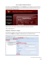
GENERAL CONFIGURATION
- Open your network browser, and go to:
- The landing page to login to the device will appear. On this screen, you get an
overview of the output status of the module. In the top right corner, you will
see the device status. If the status “LED” is green, there are no alarms. When
you move your cursor over the status “LED”, the alarm status will appear.
- By clicking on login, you can log in to the module. Use the password “admin”.
! change the password as soon as you log in to the module via Management Port”!
- After logging in, the Device information window will appear again. On this
screen, you see information about the device type, name, ID, serial number,
firmware version, hardware version and device features. The menu structure of
the web interface can be found in the left column.

5500 - 5501 ProFlex
9
The following actions are critical for optimal system performance:
• Management port:
o Define the hostname and IP settings of your management port:
Here you can configure the hostname of the module. This name
can be used to access the module by simply typing it into your
browser as the address and surf to it. This is more convenient
than using the IP address.
o Change your password to secure your module for unauthorized users
• Streaming port:
o Define the IP settings of your streaming port.
o Set Time-to-Live according to your network needs (default is 64)
o Set Encapsulation to UDP or RTP
• Firmware Upgrade:
o Click on the BROWSE button and open the upgrade file. Click UPLOAD to
send the file to the device, this will install the new firmware on the
device.
• License management:
o For first configuration, the device license is already set and should not
be altered.
o For a license upgrade, first upload the license file* and then activate the
device license via “Activate Device License” and press Apply. Finally,
reboot the device to make sure the firmware upgrade succeeds.
* the procedure to obtain a new license file is to send your current license identifier (LID) to
UnitronGroup and request for a new configuration according to your needs
• Device Settings:
o Go to this tab if you want to import a settings file from another module
(click on choose file and select the .exp file on your computer), or
export a settings file (so you can later upload it to another module).
o This tab can also be used to store and restore the device settings
• Reset device:
o If it is at issue, go to the Reset Device tab to reboot your ProFlex. Via
this tab you can also reset certain settings or restore the default
configurations of your ProFlex. All settings can be reset to default by
means of a factory reset.
o The ProFlex can also be manually reset. This can be done by inserting a
pin (e.g. a paperclip) in the small opening in the front plate of the
ProFlex right above the letters “GND” (between the power and alarm
LEDs).
▪ By pressing this button less than 2 seconds (LED above
management port will turn RED), the device will reboot
▪ By pressing this button longer than 5 seconds (LED above
management port will blink GREEN), the device will reboot, the IP
settings will be reset and the password will be reset to the
default, i.e. “admin”.
• Logout:
o When you are finished configuring the ProFlex, click logout to secure
the web interface for unauthorized users.

5500 - 5501 ProFlex
10
DEVICE CONFIGURATION
It is of utmost importance that your device is configured in a right way in order to make the
ProFlex installation successful. To do so, follow the below mentioned steps carefully.
1. Input
1.1 Define the LNB settings (INPUT > LNB)
o Label: custom label for each input (e.g. VLow, or ASTRA
19.2VLow, …)
o Voltage: The LNB voltage to select the polarization
▪ 13V: Vertical polarization
▪ 18V: Horizontal polarization
o Extended Voltage: Add 1V to the LNB voltage to compensate the
cable losses for long coaxial cables.
o Tone: LNB tone to select low/high band
▪ ON: high band
▪ OFF: low band
o DiSEqC®: control of a DiSEqC® switch (A/B/C/D)
o Band: Satellite band
▪ Ku-band (LO 9750/10600)
▪ C-band (LO 5150)
▪ S-band (LO 3620)
▪ KU (LO 10750)
▪ KU (LO 11300)
o Enable: do not forget to enable the LNB input, this is disabled by
default)
o Press APPLY to confirm the parameters.

5500 - 5501 ProFlex
11
1.2 Define the settings for each of the 8 tuners (INPUT > TUNER)
o Input: this refers to the LNB inputs; make sure the transponder
frequencies you choose correspond to the right polarity of the LNB
inputs
o Frequency: choose the frequency of the transponder you want to
receive
o Baud Rate: choose the baud rate of the transponder signal you want to
receive
o Modulation: choose between DVB-S and DVB-S2
o Enable: click the tick box to enable the tuner (this is disabled by
default)
o Press APPLY to confirm the parameters.
o Check the lock status, signal level, signal quality and signal to Noiseto
see if the tuner locks on the selected transponder
o The module will now set the tuner to this frequency. Wait until the
correct parameters are loaded. When the tuner is able to lock on
the frequency, the services status from this transponder will be
shown.

5500 - 5501 ProFlex
12
2. Output
* depending on the configuration of your ProFlex
2.1 Set all the SPTS* (OUTPUT > SPTS)
o Status
▪ The bitrate bar shows the total bitrate of all enabled services
combined in the cluster. The ProFlex disposes of 4 SPTS clusters,
each cluster can contain up to 16 services. The maximum bitrate
per cluster is 100 Mbps. It is however advisable to keep a buffer
of 20%, to prevent possible overflow (bitrate of services can
fluctuate in time).
o Service Settings
▪ To add a service, select tuner, name, CI and Priority, then click +
▪ Click arrow down symbol (V) to drop down the tuner menu. If
necessary, you can block services. Click the save icon to save
your changes.
▪ Select another cluster by clicking on the tabs on top of the page
to add more services.
o PID Settings
▪ Block Private Data: This option blocks private data tables that do
not serve a clear purpose. Everything what is not recognized as
video or audio will be blocked.
* or MPTS according to the configuration of your ProFlex

5500 - 5501 ProFlex
13
2.2 Set all the Mux* (OUTPUT > MUX)
o Modulation Settings
▪ Frequency(kHz): Here you can select the frequency you want to
transmit on. For DVB-T: 47000 to 862000, for DVB-C: 47000 to
1002000
▪ Bandwidth: Choose the desired bandwidth.
▪ Constellation: Choose the type of constellation you want to use.
(64QAM, 16QAM, QPSK)
▪ Code Rate: select the code rate (N/A, 1/2, 2/3, 3/4, 5/6 or 7/8)
▪ Guard Interval: select the guard interval (N/A, 1/32, 1/16, 1/8,
or 1/4)
▪ Level(dBm): define the level of RF (between -25 to -40)
▪ Enable: click the tick box to enable the tuner (this is
disabled by default)
▪ Press APPLY to confirm the parameters.
o Transport Stream Settings
▪ TSID: Choose your Transport Stream ID

5500 - 5501 ProFlex
14
o Status
▪ The bitrate bar shows the current bitrate of the selected
multiplex. Depending on the model, the ProFlex disposes of 4 or
8 multiplexes. The maximum bitrate per MUX is 31 Mbps (DVB-T)
or 50 Mbps (DVB-C). It is however advisable to keep a buffer of
20% to prevent possible overflow (bitrate of services can fluctuate
in time). Select another multiplex by clicking on the tabs on top
of the page.
o Service Settings
▪ To add a service, select tuner, name, CI and Priority, New Sid, LCN
then click +
▪ Click arrow down symbol (V) to drop down the tuner menu. If
necessary, you can block services. Click the save icon to save
your changes.
▪ Select another cluster by clicking on the tabs on top of the page
to add more services.
o PID Settings
▪ Block Private Data: This option blocks private data tables that do
not serve a clear purpose. Everything what is not recognized as
video or audio will be blocked.

5500 - 5501 ProFlex
15
2.3 Define the networks (OUTPUT > NETWORK)
o ONID: The Original_Network_ID (ONID) is defined as the “unique
identifier of a network”, check the spreadsheets on
http://www.dvbservices.com to find your correct ONID
o NID: Choose your Network ID
o Network Name: set your network name
o Version: set the version of the network (value between 0 and 31)
o Private Data Specifier: choose between EACEM – ITC – NORDIG
o Press APPLY to confirm the parameters.

5500 - 5501 ProFlex
16
3. CAM
3.1 Set the CAM configurations for the ProFlex (CAM)
o Type: To prevent network overflow, it is important to choose the type of
the CAM (this can be found on you CAM-card:
▪ Low-speed (legacy CAM) up to 50 Mbps
▪ High-speed (modern CAM) up to 100 Mbps
o Watchdog: The watchdog monitors the scrambling status of all services
going through the CAM. In case one or more service sare no longer
descrambled, the watchdog will proceed to the reset of the CAM module
to try to restore the descrambling of the service(s). Activate this feature
only once all services are properly descrambled by the CAM module.
o Reference Transponder: It is necessary to enable and select a reference
transponder in the CAM menu (for each CAM individually). The CAM
module needs authorization to descramble services. Select the reference
transponder with authorization information for each CAM individually.
o Press APPLY to confirm the parameters.

5500 - 5501 ProFlex
17
3. TECHNICAL SPECIFICATIONS
General
Dimensions
-
5 RU x 8 TE x 367 mm
Consumption
A
1.2 (ref. 5500) - 1.8 (ref. 5501)
Power supply voltage
VDC
15
Integrated multiswitch
-
Yes, allows flexible routing of satellite programs to
multiplexes (QAM or QOFDM)
Configuration
-
Built-in webserver or optional UUI configuration software
Remote access
-
via RMU ref. 5951 or 5952
Encoded programs
-
From all 8 tuners.
Can be routed through the CAMs and can be decoded
using multi-service CAMs
Configuration possibilities
1
-
DVB-S/S2 to DVB-C
2
-
DVB-S/S2 to DVB-T
3
-
DVB-S/S2 to IPTV
4
-
DVB-S/S2 to IP
Feature possibilities
1
#Tuners
1 to 8
2
#Mux
1 to 8
3
#CAM
0 to 4
4
#SPTS
16, 32, 48, 64
5
#MPTS
1 to 4

5500 - 5501 ProFlex
18
Input: DVB-S/S2
Inputs
-
4 x F female (75Ω) (with passive loop-through)
Loop-through loss
dB
2.5
RF switch
-
4 x 8
Number of satellite tuners
-
8
Input level
dBµV
42 – 98
Frequency range
MHz
950 – 2150
LO frequency
- Ku-band
- C-band
- S-band
- Ku-band
- Ku-band
MHz
9750/10600
5150
3620
10750
11300
Supported modulation
-
DVB-S QPSK: 1/2, 2/3, 3/4, 5/6, 7/8
DVB-S2 QPSK: 1/2, 3/5, 2/3, 3/4, 4/5, 5/6, 8/9, 9/10
DVB-S2 8PSK: 3/5, 2/3, 3/4, 5/6, 8/9, 9/10
LNB control and powering
- band
- polarity
- current
- control
kHz
V
mA
-
0, 22
0, 13, 18
350 per input
DiSEqC 1.0
Output: DVB-T
Standard
-
EN 300 744
DVB-T output connector
-
F female (75Ω)
DVB-T input
- connector type
loop-through
-
F female (75Ω)
directional coupled
Loop-through loss
dB
2.5
Return loss
dB
10
RF channel(s)
- Quad
- Octo (only for Ref. 5501)
-
-
4 adjacent channels in a 32 MHz window
4+4 adjacent channels in a 32+32 MHz window
Number of services per
multiplex
-
up to full bandwidth
(up to 31.7 Mbps / multiplex)
Selectable channel
frequency range
MHz
47 – 862
Output frequency step
KHz
1
Bandwidth
MHz
6,7,8
Output level
dBm
69 – 84
Output level step
dBm
1
Spurious in band
dBc
-50
MER (Modulation Error Ratio)
dB
≥ 43

5500 - 5501 ProFlex
19
OFDM mode
-
2K
Constellation
-
QPSK, 16-QAM, 64-QAM
FEC (forward error
correction)
-
1/2, 2/3, 3/4, 5/6, 7/8
Guard interval
-
1/4, 1/8, 1/16, 1/32
Transmission
-
Non-hierarchical
Shoulder Attenuation
dB
4
Frequency stability
ppm
-5 - +5
Phase noise @ 10 KHz
dBc/Hz
-98
Output: DVB-C
Standard
-
EN 300 429
ITU-T J.83 Annex A & Annex C
DVB-C output connector
-
F female (75Ω)
DVB-C input connector
(loop-through)
-
F female (75Ω)
Loop-through loss
dB
2.5
Return loss
dB
10
RF channel(s)
- Quad
- Octo (only for 5501)
-
-
4 adjacent channels in a 32 MHz window
4+4 adjacent channels in a 32+32 MHz window
Number of services per
multiplex
-
up to full bandwidth
(up to 51.3 Mbps / multiplex)
Selectable channel
frequency range
MHz
47 - 1002
Output frequency step
KHz
1
Bandwidth
MHz
6,7,8
Baudrate
Mbaud
1.0 – 7.0
Constellation
-
16-QAM, 32-QAM, 64-QAM, 128-QAM, 256-QAM
Output level
dBµV
69 – 84
Output level step
dBµV
1
Spurious in band
dBc
-50
Spectral inversion
-
ON/OFF
Unequalized MER
dB
≥ 43
Shoulder Attenuation
dB
43
Frequency stability
ppm
-5 - +5
Phase noise @ 10 KHz
dBc/Hz
-98
/