SystemAir SYSPLIT DUCT 24 LNS HP Q Owner's manual
- Category
- Split-system air conditioners
- Type
- Owner's manual

MIDDLE STATIC PRESSURE DUCT TYPE AIR CONDITIONER
Installation Manual
Middle Static Pressure Duct Type
IMPORTANT NOTE:
Read this manual carefully before
installing or operating your new air
conditioning unit. Make sure to save
this manual for future reference.
SYSPLIT DUCT

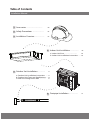
Accessories .................................................... 04
a. Indoor Unit Parts ........................................ 08
b. Indoor Unit Installation Instructions ....... 08
Safety Precautions ..................................... 05
Outdoor Unit Installation ......................... 13
a. Outdoor Unit Installation Instructions ...... 13
b. Outdoor Unit Types and Specifications .... 14
c. Notes on Drilling Hole in Wall .................... 15
Drainpipe Installation ............................... 16
Table of Contents
Installation Manual
Indoor Unit Installation ........................... 08
Installation Overview ............................... 07
1
2
5
3
4
6
Indoor Unit Installation ........................... 07

Page 3
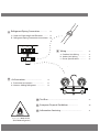
Refrigerant Piping Connection ....................... 18
A. Notes on Pipe Length and Elevation .............. 18
B. Refrigerant Piping Connection Instructions ...20
Wiring ................................................. 22
a. Outdoor Unit Wiring .................. 22
b. Indoor Unit Wiring ..................... 23
c. Power Specifications ................... 25
Air Evacuation .................................................. 27
a. Evacuation Instructions ................................ 27
b. Note on Adding Refrigerant ....................... 28
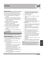
Test Run .......................................................................................... 29
MC MC
7
8
9
10
L N
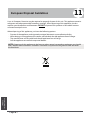
European Disposal Guidelines ............................ 30
11
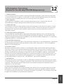
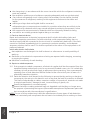
Information Servicing ............................................................... 31
12
(R32/R290 refrigerant )
C au t i o n: Risk of fire

Page 4
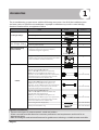
Accessories 1
The air conditioning system comes with the following accessories. Use all of the installation parts
and accessories to install the air conditioner. Improper installation may result in water leakage,
electrical shock and re, or equipment failure.
Connecting wire for display (2m)
Cord protection rubber ring
QUANTITY
SHAPENAME
Soundproof / insulation sheath 2
1
1
1
Tubing & Fittings
Others
Installation manual
Transfer connector(Φ12.7-Φ15.9)/
( )(Packed with the indoor unit )
NOTE: Pipe size may dier from appliance to
appliance. To meet dierent pipe size requirements,
sometimes the pipe connections need a transfer
connector installed on the outdoor unit .
Transfer connector(Φ6.35-Φ9.52)/
( )(Packed with the indoor unit)
NOTE: Pipe size may dier from appliance to
appliance. To meet dierent pipe size requirements,
sometimes the pipe connections need a transfer
connector installed on the outdoor unit .
Transfer connector(Φ9.52-Φ12.7)/
( ) (Packed with the indoor unit,
used for multi-type models only )
NOTE: Pipe size may dier from appliance to
appliance. To meet dierent pipe size requirements,
sometimes the pipe connections need a transfer
connector installed on the outdoor unit .
1
Owner‘s manual
Drain joint (some models)
Seal ring (some models)
Drainpipe Fittings
(for cooling & heating)
Seal sponge (some models)
EMC Magnetic Ring
(some models)
Magnetic ring
(wrap the electric wires S1 & S2 ( P & Q & E )
around the magnetic ring twice)
Magnetic ring
(Hitch on the connective cable between the indoor
unit and outdoor unit after installation.)
1
1
Orice (some models) 1
Φ0.5in-Φ0.63in
Φ0.25in-Φ0.375in
Φ0.375in-Φ0.5in
1
(on some models)
1
(on some models)
1
(on some models)
1(on some models)
1(on some models)
1
Optional accessories
There are two types of remote controls: wired and wireless.
Select a remote controller based on customer preferences and requirements and install in an
appropriate place.
Refer to catalogues and technical literature for guidance on selecting a suitable remote controller.
•
S1&S2(P&Q&E)

Page 5
Safety Precautions 2
Read Safety Precautions Before Installation
Incorrect installation due to ignoring instructions can cause serious damage or injury.
The seriousness of potential damage or injuries is classified as either a WARNING or CAUTION.
Failure to observe a warning may result in death. The appliance must be installed in
accordance with national regulations.
Failure to observe a caution may result in injury or equipment damage.
WARNING
CAUTION
WARNING
•Appliance shall be installed, operated and stored in a room with a oor area larger than X m²,
installation of pipe-work shall be kept to a minimum X m²(Please see the following form ).
The appliance shall not be installed in an unventilated space, if that space is smaller than X m²
(Please see the following form ).Spaces where refrigerant pipes shall be compliance with
national gas regulations.
•Any person who is involved with working on or breaking into a refrigerant circuit should hold a
current valid certicate from an industry-accredited assessment authority, which authorises their
competence to handle refrigerants safely in accordance with an industry recognised assessment
specication.
•Servicing shall only be performed as recommended by the equipment manufacturer.
Maintenance and repair requiring the assistance of other skilled personnel shall be carried out
under the supervision of the person competent in the use of ammable refrigerants.
•Appliance shall be stored in a well-ventilated area where the room size corresponds to the room
area as specied for operation.
•Appliance shall be stored in a room without continuously operating open ames (for example
an operating gas appliance) and ignition sources (for example an operating electric heater).
•The appliance shall be stored in a room without continuously operating ignition sources
(for example: open ames, an operating gas appliance or an operating electric heater).
•Do not pierce or burn.
•The appliance shall be stored so as to prevent mechanical damage from occurring.
•
• Be aware that the refrigerants may not contain an odour.
•Keep ventilation openings clear of obstruction.
Compliance with national gas regulations shall be observed.
•A warning that the appliance shall be stored in a well-ventilated area where the room size
corresponds to the room area as specied for operation.
•The appliance shall be stored in a room without continuously operating ignition sources
(for example: open ames, an operating gas appliance or an operating electric heater).
Do not pierce or burn.
The appliance shall be stored so as to prevent mechanical damage from occurring.
Be aware that the refrigerants may not contain an odour.
Compliance with national gas regulations shall be observed.
Keep ventilation openings clear of obstruction.
A warning that the appliance shall be stored in a well-ventilated area where the room size
corresponds to the room area as specied for operation.
•
•
•
•
•
•

Page 6 Page 6
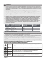
Amount of refrigerant
to be charged (kg) maximum installation
height (m) Minimum room
area (m²)
≤2.048 1.8m 4
2.048-3.0 1.8m 8
>3.0 1.8m 9
Model
(Btu/h)
≤30000
30000-48000
>48000
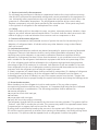
Note about Fluorinated Gasses
1. This air-conditioning unit contains fluorinated gasses. For specific information on the type of gas
and the amount, please refer to the relevant label on the unit itself.
2.
Installation, service, maintenance and repair of this unit must be performed by a certified technician.
3. Product uninstallation and recycling must be performed by a certified technician.
4. If the system has a leak-detection system installed, it must be checked for leaks at least every 12
months.
5.
When the unit is checked for leaks, proper record-keeping of all checks is strongly recommended.
CAUTION
CAUTION
CAUTION
This symbol shows that a service personnel should be handling this
equipment with reference to the installation manual.
This symbol shows that information is available such as the operating
manual or installation manual.
This symbol shows that this appliance uses a ammable refrigerant. If the
refrigerant is leaked and exposed to an external ignition source, there is a
risk of re.
This symbol shows that the operation manual should be read carefully.
WARNING
CAUTION
Explanation of symbols displayed on the indoor unit or outdoor unia
(applicable to the unit adopts R32/R290 Refrigerant only):
WARNING
•Appliance shall be installed, operated and stored in a room with a oor area larger than X m²,
installation of pipe-work shall be kept to a minimum X m²(Please see the following form ).
The appliance shall not be installed in an unventilated space, if that space is smaller than X m²
(Please see the following form ).Spaces where refrigerant pipes shall be compliance with
national gas regulations.
•Any person who is involved with working on or breaking into a refrigerant circuit should hold a
current valid certicate from an industry-accredited assessment authority, which authorises their
competence to handle refrigerants safely in accordance with an industry recognised assessment
specication.
•Servicing shall only be performed as recommended by the equipment manufacturer.
Maintenance and repair requiring the assistance of other skilled personnel shall be carried out
under the supervision of the person competent in the use of ammable refrigerants.
•Appliance shall be stored in a well-ventilated area where the room size corresponds to the room
area as specied for operation.
•Appliance shall be stored in a room without continuously operating open ames (for example
an operating gas appliance) and ignition sources (for example an operating electric heater).

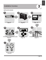
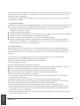
Overview
Installation Overview 3
L N
123
4
5
MC MC
6
7
Install the indoor unit
(Page 8)
INSTALLATION ORDER
Install the outdoor unit
(Page 13) Install the drainpipe
(Page 16)
Evacuate the refrigeration system
(Page 27) Connect the wires
(Page 22) Connect the refrigerant pipes
(Page 18)
Perform a test run
(Page 29)
Page 7

Page 8
Unit Installation
Indoor Unit
Installation
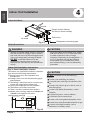
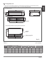
Indoor Unit Installation 4
Indoor Unit Parts
Fig. 4.1
WARNING
•Securely install the indoor unit on a structure
that can sustain its weight. If the structure is
too weak, the unit may fall causing personal
injury, unit and property damage or death.
•DO NOT install the indoor unit in the
bathroom or laundry room as excessive
moisture can short the unit and corrode the
wiring.
CAUTION
•Install the indoor and outdoor units, cables
and wires at least 1m (3.2’) from televisions
or radios to prevent static or image
distortion. Depending on the appliances, a
1m (3.2’) distance may not be sufficient.
•If the indoor unit is installed on a metal
part of the building, it must be electrically
grounded.
Indoor Unit Installation Instructions
Step 1: Select installation location
The indoor unit should be installed in a location
that meets the following requirements:
Enough room exists for installation and
maintenance.
Enough room exists for the connecting pipe
and drainpipe.
The ceiling is horizontal and its structure can
sustain the weight of the indoor unit.
The air inlet and outlet are not impeded.
The airflow can fill the entire room.
There is no direct radiation from heaters.
CAUTION
DO NOT install the unit in the following
locations:
In areas with oil drilling or fracking
In coastal areas with high salt content in the
air
In areas with caustic gases in the air, such as
near hot springs
In areas with power fluctuations, such as
factories
In enclosed spaces, such as cabinets
In kitchens that use natural gas
In areas with strong electromagnetic waves
In areas that store flammable materials or gas
In rooms with high humidity, such as
bathrooms or laundry rooms
Fig. 4.2
Air outlet
Air inlet
Air filter(on some models)
Drain hose
Electric control cabinet
Refrigerant connecting pipe
checking orice
60cmX60cm
30cm or more
20cm or more
Maintenance roomage
√
√
√
√
√
√
Safety Precautions
Models with a cooling capacity of 9000Btu to
18000Btu only apply to one room.
√

Page 9
Indoor Unit
Installation
Fig. 4.3
Step 2: Hang indoor unit.
1. Please refer to the following diagrams to locate the four positioning screw bolt holes on the
ceiling. Be sure to mark the paces where you will drill ceiling hook holes.
Air outlet dimensions
Air inlet dimensions
Air lter
Descending ventilation opening and mounted hook
Air lter
Electric control box
Table.4-1 (unit: mm/inch)
MODEL
(Btu/h)
Outline dimension
A B C
air outlet opening size
D E F
air return opening size
Size of mounted lug
I
J
G
H
18K 210/8.3 674/26.5880/34.6
24K 249/9.8 774/30.51100/43.3
36K 249/9.8 774/30.51360/53.5
48K~60K 300/11.8 874/34.41200/47.2
136/5.4 706/27.8600/23.6
175/6.9 926/36.5700/27.6
175/6.9 1186/46.7700/27.6
227/8.9 1044/41.1800/31.5
190/7.5
228/8.9
228/8.9
280/11
920/36.2782/30.8
1140/44.91001/39.4
1400/55.11261/49.6
1240/48.81101/43.3
508/20
598/23.5
598/23.5
697/27.4
12K 200/7.9 506/19.9700/27.6 152/6 537/21.1450/17.7 186/7.3 741/29.2599/23.6
360/14.2

Indoor Unit
Installation
Page 10
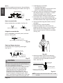
Cut o the roof beam.
Strengthen the point at which the cut was
made. Consolidate the roof beam.
Fig. 4.6
Fig. 4.7
Original concrete bricks
Use an embedding screw bolt, crock, and stick
harness. (See Fig.4.6)
Steel roof beam structure
Install and use the supporting steel angle.
(See Fig.4.7)
Fig. 4.4
Wood
Place the wood mounting across the roof beam,
then install the hanging screw bolts.(See Fig.4.4)
Wood mounting
Roof beam
Hanging screw bolts
Ceiling
Fig. 4.5
New concrete bricks
Inlay or embed the screw bolts. (See Fig. 4.5)
(Blade shape insertion) (Slide insertion)
Steel bar
Embedding screw bolt
(Pipe hanging and embedding screw bolt)
Hanging screw bolt
Hanging
bolts
Supporting
angle steel
Fig. 4.9
Screw nut
Washer
Hanging screw bolt
Overhang part
Shockproof cushion
NOTE:
Conrm the minimum drain tilt is 1/100
or more.
CAUTION
The unit body must be completely aligned with
the hole. Ensure that the unit and the hole are
the same size before moving on.
2. Install and t pipes and wires after you have
nished installing the main body.When
choosing where to start, determine the
direction of the pipes to be drawn out.
Especially in cases where there is a ceiling
involved, align the refrigerant pipes, drain
pipes, and indoor and outdoor lines with their
connection points before mounting the unit.
3. Install hanging screw bolts.
4. After you select an installation location,align
the refrigerant pipes, drain pipes, as well as
indoor and outdoor wires with their
connection points before mounting the unit.
5. Drill 4 holes 10cm (4”) deep at the ceiling
hook positions in the internal ceiling. Be sure
to hold the drill at a 90° angle to the ceiling.
6. Secure the bolt using the washers and nuts
provided.
7. Install the four suspension bolts.
8. Mount the indoor unit with at least two
people to lift and secure it. Insert suspension
bolts into the unit’s hanging holes. Fasten
them using the washers and nuts provided.
(See Fig. 4.8).
9. Mount the indoor unit onto the hanging
screw bolts with a block. Position the indoor
unit at using a level indicator to prevent
leaks. (See Fig. 4.9).
Fig. 4.8

Page 11
Indoor Unit
Installation
Fig. 4.10
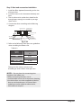
Step 3: Duct and accessories installation
NOTE: 1. Do not place the connecting duct
weight on the indoor unit.
2.When connecting the duct, use an
nonammable canvas tie-in to prevent vibrating.
3.Insulation foam must be wrapped outside the
duct to avoid condensate. An internal duct
underlayer can be added to reduce noise,
if the end-user requires.
1. Install the lter (optional) according to the size
of the air inlet.
5. Refer to the following static pressure guidelines
when installing the indoor unit.
Change the fan motor static pressure
according to external duct static pressure.
2. Install the canvas tie-in between the body and
duct.
3. The air inlet and air outlet duct should be far
enough apart enough to a avoid air passage
short-circuit.
4. Connect the duct according to the following
diagram:
Canvas tie-in Canvas tie-in
Air outlet Isolation booth
Isolation booth
checking orice
Air inlet
Air dust lter
Table.4-2
12K 0~60
18K 0~100
24K~36K 0~160
48K~60K 0~160
MODEL
(Btu/h)
Static Pressure
(Pa)

Page 12
Indoor Unit
Installation
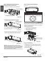
Step 4: Adjust the air inlet direction
(From rear side to under-side.)
1. Take o the ventilation panel and ange.
2. Change the mounting positions of the
ventilation panel and air return ange.
Air return ange
Ventilation panel
3. When installing the lter mesh, t it into the
ange as illustrated in the following gure.
NOTE: All the gures in this manual are for
demonstration purposes only. The air conditioner
you have purchased may be slightly dierent in
design, though similar in shape.
Step 5: Fresh air duct installation
Dimension : Duct joint for fresh air
Ø125mm(4.92”) Ø160mm(6.3”)
MODLE
18-60
Step 6: Motor and drain pump maintenance
Motor maintenance:
Take o the ventilated panel.
Take o the blower housing.
Take o the motor.
1.
2.
3.
(the rear ventilated panel is used as an example)
Mofor
Blower housing
Ventilated panel
Pump maintainance:
Remove four screws from the drain pump.
Unplug the pump power supply and water
level switch cable.
Detach the pump.
1.
2.
3.
Pump
Fig. 4.11
Fig. 4.12
Fig. 4.13
Fig. 4.14
Fig. 4.15
Fig. 4.16
Air return ange
Ventilation panel

Installation
Page 13
Outdoor Unit Installation
Outdoor Unit Installation Instructions
Step 1: Select installation location.
The outdoor unit should be installed in the
location that meets the following requirements:
Place the outdoor unit as close to the indoor
unit as possible.
Ensure that there is enough room for
installation and maintenance.
The air inlet and outlet must not be
obstructed or exposed to strong wind.
Ensure the location of the unit will not be
subject to snowdrifts, accumulation of leaves
or other seasonal debris. If possible, provide
an awning for the unit. Ensure the awning
does not obstruct airflow.
The installation area must be dry and well
ventilated.
There must be enough room to install the
connecting pipes and cables and to access
them for maintenance.
The area must be free of combustible gases
and chemicals.
The pipe length between the outdoor and
indoor unit may not exceed the maximum
allowable pipe length.
If possible, DO NOT install the unit where it
is exposed to direct sunlight.
If possible, make sure the unit is located far
away from your neighbors’ property so that
the noise from the unit will not disturb them.
If the location is exposed to strong winds (for
example: near a seaside), the unit must be
placed against the wall to shelter it from the
wind. If necessary, use an awning.
(See Fig. 5.1 & 5.2)
Install the indoor and outdoor units, cables
and wires at least 1 meter from televisions or
radios to prevent static or image distortion.
Depending on the radio waves, a 1 meter
distance may not be enough to eliminate all
interference.
Strong wind
Strong wind
Strong wind
Fig. 5.1 Fig. 5.2
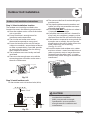
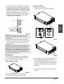
Step 2: Install outdoor unit.
Fix the outdoor unit with anchor bolts (M10)
>60cm / 23.6”
Fix with bolts
CAUTION
•Be sure to remove any obstacles that
may block air circulation.
•Make sure you refer to Length
Specifications to ensure there is
enough room for installation and
maintenance.
Fig. 5.3
5
√
√
√
√
√
√
√
√
√
√
√
√

Page 14
Outdoor Unit
Outdoor Unit
Installation
Air Outlet
(Wall or obstacle)
H
D
W
Air inlet
Air inlet Air inlet
Air inlet
(Wall or obstacle)
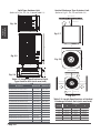
Table 5.1: Length Specifications of Split
Type Outdoor Unit (unit: mm/inch)
Table 5.2: Length Specifications of Vertical
Discharge Outdoor Unit (unit: mm/inch)
MODEL
DIMENSIONS
W H D
18 633/25 554/21.8554/21.8
24 633/25 554/21.8554/21.8
36 759/29.8 554/21.8554/21.8
36 633/25 600/23.6600/23.6
48 759/29.8 710/28710/28
60 843/33 710/28710/28
Split Type Outdoor Unit
(Refer to Fig 5.4, 5.5, 5.6, 5.10 and Table 5.1)
Vertical Discharge Type Outdoor Unit
(Refer to Fig 5.7, 5.8, 5.9 and Table 5.2)
Fig. 5.7
Fig. 5.8
Fig. 5.9
Fig. 5.6
Fig. 5.5
A
B
D
W
H
W
H
Fig. 5.4
Outdoor Unit Dimensions
W x H x D
Mounting Dimensions
Distance A Distance B
760x590x285 (29.9x23.2x11.2) 530 (20.85) 290 (11.4)
810x558x310 (31.9x22x12.2) 549 (21.6) 325 (12.8)
845x700x320 (33.27x27.5x12.6) 560 (22) 335 (13.2)
900x860x315 (35.4x33.85x12.4) 590 (23.2) 333 (13.1)
945x810x395 (37.2x31.9x15.55) 640 (25.2) 405 (15.95)
990x965x345 (38.98x38x13.58) 624 (24.58) 366 (14.4)
946x810x420 (37.24x31.9x16.53) 673 (26.5) 403 (15.87)
946x810x410 (37.24x31.9x16.14) 673 (26.5) 403 (15.87)
952x1333x410 (37.5x52.5x16.14) 634 (24.96) 404 (15.9)
952x1333x415 (37.5x52.5x16.34) 634 (24.96) 404 (15.9)
845x702x363 (33.27x27.6x14.3) 540 (21.26) 350 (13.8)
938x1369x392 (36.93x53.9x15.43) 634 (24.96) 404 (15.9)
900x1170x350 (35.4x46x13.8) 590 (23.2) 378 (14.88)
800x554x333 (31.5x21.8x13.1) 514 (20.24) 340 (13.39)
>152.4cm / 60”
>45.7cm / 18” >45.7cm / 18”
>45.7cm / 18”
>45.7cm / 18”

Page 15
Outdoor Unit
Installation
NOTE: The minimum distance between the
outdoor unit and walls described in the
installation guide does not apply to airtight
rooms. Be sure to keep the unit unobstructed
in at least two of the three directions (M, N, P)
(See Fig. 5.10)
M
N
P
30 cm / 11.8” from back wall
60 cm / 23.6” on right
60 cm / 23.6” above
30 cm / 11.8” on left
200 cm / 78” in front
Fig. 5.10
Fig. 5.11
NOTE: Make sure the water drains to a safe
location where it will not cause water damage
or a slipping hazard.
Seal
Drain joint
(A) (B)
Base pan hole of
outdoor unit
Seal
Fig. 5.12
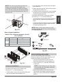
Notes On Drilling Hole In Wall
You must drill a hole in the wall for the
refrigerant piping, and the signal cable that will
connect the indoor and outdoor units.
1. Determine the location of the wall hole
based on the location of the outdoor unit.
2. Using a 65-mm (2.5”) core drill, drill a hole
in the wall.
NOTE: When drilling the wall hole, make
sure to avoid wires, plumbing, and other
sensitive components.
3. Place the protective wall cu in the hole.
This protects the edges of the hole and will
help seal it when you nish the installation
process.
Fig. 5.11
L
H
300 cm / 118” or more
A
60 cm / 23.6”
or more
150 cm / 59”
or more
25 cm / 9.8”
or more
25 cm / 9.8”
or more
Rows of series installation
L ≤ H L ≤ 1/2H
L A
25 cm / 9.8” or more
1/2H < L ≤ H
30 cm / 11.8” or more
L H Can not be installed
Table 5.3 The relations between H, A and L
are as follows.
Drain Joint Installation
If the drain joint comes with a rubber seal
(see Fig. 5.12 - A ), do the following:
1. Fit the rubber seal on the end of the drain joint
that will connect to the outdoor unit.
2. Insert the drain joint into the hole in the base
pan of the unit.
3. Rotate the drain joint 90° until it clicks in place
facing the front of the unit.
4. Connect a drain hose extension (not included)
to the drain joint to redirect water from the
unit during heating mode.
If the drain joint doesn’t come with a rubber
seal (see Fig. 5.12 - B ), do the following:
Insert the drain joint into the hole in the base
pan of the unit. The drain joint will click in
place.
Connect a drain hose extension (not included)
to the drain joint to redirect water from the
unit during heating mode.

Page 16
Drainpipe
Installation
Fig. 6.3
(39-59”)
(7.9”)
<20cm
(21.7”)
55cm
Lean over 1/50
1-1.5m1-1
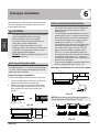
Drainpipe installation for units with a pump
Ceiling
0 - 75mm
(3”)
NOTE ON DRAINPIPE INSTALLATION
•When using an extended drainpipe, tighten
the indoor connection with an additional
protection tube. This prevents it from
pulling loose.
•The drainpipe should slope downward at a
gradient of at least 1/100 to prevent water
from flowing back into the air conditioner.
•To prevent the pipe from sagging, space
hanging wires every 1-1.5m (39-59”).
•If the outlet of the drainpipe is higher than
the body’s pump joint, use a lift pipe for
the indoor unit’s exhaust outlet. The lift
pipe must be installed no higher than
55cm (21.7”) from the ceiling board. The
distance between the unit and the lift pipe
must be less than 20cm (7.9”). Incorrect
installation could cause water to ow back
into the unit and ood.
The drainpipe is used to drain water away from
the unit. Improper installation may cause unit
and property damage.
CAUTION
•Insulate all piping to prevent condensation,
which could lead to water damage.
•If the drainpipe is bent or installed
incorrectly, water may leak and cause a
water-level switch malfunction.
•In HEAT mode, the outdoor unit will
discharge water. Ensure that the drain hose
is placed in an appropriate area to avoid
water damage and slippage.
•DO NOT pull the drainpipe forcefully. This
could disconnect it.
NOTE ON PURCHASING PIPES
This installation requires a polyethylene tube
(outside diameter = 3.7-3.9cm, inside diameter
= 3.2cm), which can be obtained at your local
hardware store or dealer.
Indoor Drainpipe Installation
Install the drainpipe as illustrated in Figure 6.2.
1.
2.
Drainpipe
connecting port
Drain hose
Pipe clasp Insulation
Fig. 6.1
Drainpipe Installation
Fig. 6.2
6
Cover the drainpipe with heat insulation to
prevent condensation and leakage.
Attach the mouth of the drain hose to the
unit’s outlet pipe. Sheath the mouth of the
hose and clip it rmly with a pipe clasp.
(Fig 6.1)
NOTE: When connecting multiple drainpipes,
install the pipes as illustrated in Fig 6.4.
(39-59”)
1-1.5m1-1
Lean over 1/50
Ceiling
•To prevent air bubbles, keep the drain hose
level or slightly tiled up (<75mm / 3”).
0-53cm
(20.8”)
≥10cm
(4”)
Fig. 6.4

Page 17
Drainpipe
Installation
Drainage test
Check whether the drainpipe is unhindered.
This test should be performed on newly built
houses before the ceiling is paved.
Units with a pump.
Units without a pump.
1. Remove the test cover.
Fill the water pan with 2 liters of water.
2. Turn on the unit in COOLING mode. You will
hear the drain pump.Check whether the
water is discharged properly (a 1-minute lag
is possible, depending on the length of the
drain pipe), Check whether water leaks from
the joints.
3. Turn o the air conditioner and put the cap
back on.
3. Using a 65-mm (2.5”) core drill, drill a hole in
the wall. Make sure that the hole is drilled at
a slight downward angle, so that the outdoor
end of the hole is lower than the indoor end
by about 12mm (0.5”). This will ensure proper
water drainage (See Fig. 6.5). Place the
protective wall cu in the hole. This protects
the edges of the hole and will help seal it
once you nish installation.
Wall
IndoorOutdoor
≈ 12mm 0.5 inch
Fig. 6.5
NOTE: When drilling the hole, make sure to
avoid wires, plumbing, and other sensitive
components.
4. Pass the drain hose through the wall hole.
Make sure the water drains to a safe location
where it will not cause water damage or a
slipping hazard.
NOTE: The drainpipe outlet should be at least
5cm (1.9”) above the ground. If it touches the
ground, the unit may become blocked and
malfunction. If you discharge the water directly
into a sewer, make sure that the drain has a U
or S pipe to catch odors that might otherwise
come back into the house.
Test cap Fig.6.7
Fig.6.8
C
L
O
S
E
D
O
P
E
N
C
L
O
S
E
D
O
P
E
N
Stow tube
Fig.6.6
Stow tube
Fill the water pan with 2 liters of water.
Check that the drainpipe is unhindered.

Page 18
Refrigerant Piping
Connection
Refrigerant Piping Connection
Safety Precautions
WARNING
•All eld piping must be completed by a
licensed technician and must comply with
the local and national regulations.
•When the air conditioner is installed in a
small room, measures must be taken to
prevent the refrigerant concentration in
the room from exceeding the safety limit
in the event of refrigerant leakage. If the
refrigerant leaks and its concentration
exceeds its proper limit, hazards due to
lack of oxygen may result.
•When installing the refrigeration system,
ensure that air, dust, moisture or foreign
substances do not enter the refrigerant
circuit. Contamination in the system may
cause poor operating capacity, high
pressure in the refrigeration cycle,
explosion or injury.
•Ventilate the area immediately if there is
refrigerant leakage during the installation.
Leaked refrigerant gas is both toxic and
flammable. Ensure there is no refrigerant
leakage after completing the installation
work.
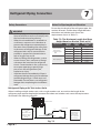
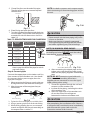
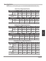
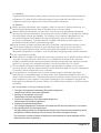
Notes On Pipe Length and Elevation
Ensure that the length of the refrigerant pipe, the
number of bends, and the drop height between
the indoor and outdoor units meets the
requirements shown in Table 7.1:
Table 7.1: The Maximum Length And Drop
Height Based on Models. (Unit: m/ft.)
Type of model Capacity
(Btu/h) Length of
piping Maximum drop
height
North America,
Australiaand the
eu frequency
conversion Split
Type
<15K 25/82 10/32.8
≥15K - <24K 30/98.4 20/65.6
≥24K - <36K 50/164 25/82
≥36K - ≤60K 65/213 30/98.4
Other Split Type
12K 15/49 8/26
18K-24K 25/82 15/49
30K-36K 30/98.4 20/65.6
42K-60K 50/164 30/98.4
Refrigerant Piping with Twin Indoor Units
When installing multiple indoor units with a single outdoor unit, ensure that the length of the
refrigerant pipe and the drop height between the indoor and outdoor units meet the requirements
illustrated in the following diagram:
LL1
L2
H2
The line branch pipe
Indoor unit
Outdoor unit
H1
Indoor unit
The drop height
between two
indoor units
must be less
than or equal to
50cm (19.6”)
The drop height
between indoor
unit
and outdoor unit
must be less than
or equal to 20m
(65.6’)
Fig. 7.1
7

Page 19
Refrigerant Piping
Connection
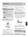
Fig. 7.2 Fig. 7.3
Oil traps
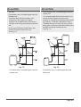
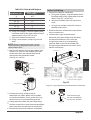
CAUTION
•
If the indoor unit is installed higher than the
outdoor unit:
An oil trap should be installed every 10m
(32.8ft) of vertical suction line riser.
(See Fig. 7.2)
-If oil flows back into the outdoor unit’s
compressor, this might cause liquid
compression or deterioration of oil return.
Oil traps in the rising gas piping can prevent
this.
CAUTION
The indoor unit is installed higher than the
outdoor unit
If the outdoor unit is installed higher than the
indoor unit:
-It is recommended that vertical suction risers
not be upsized. Proper oil return to the
compressor should be maintained with suction
gas velocity. If velocities drop below7.62m/s
(1500fpm (feet per minute)), oil return will be
decreased. An oil trap should be installed every
6m(20ft) of vertical suction line riser.
(See Fig. 7.3)
The outdoor unit is installed higher than the
indoor unit

Refrigerant Piping
Connection
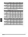
Table 7.2
Permitted length
Piping
length
Total piping length 18K+18K 30/98’ L+Max
(L1, L2)
24K+24K
30K+30K
50/164’
(farthest distance from
the line pipe branch)
15/49’ L1, L2
(farthest distance from
the line pipe branch)
10/32.8’ L1-L2
Drop
height
Drop height between
indoor and outdoor unit
20/65.6’ H1
Drop height between
two indoor units
0.5/1.6’ H2
Refrigerant Piping Connection Instructions
CAUTION
•The branching pipe must be installed
horizontally. An angle of more than 10° may
cause malfunction.
•DO NOT install the connecting pipe until both
indoor and outdoor units have been installed.
•Insulate both the gas and liquid piping to
prevent water leakage.
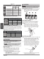
Step1: Cut pipes
When preparing refrigerant pipes, take extra
care to cut and flare them properly. This will
ensure efficient operation and minimize the
need for future maintenance.
1. Measure the distance between the indoor
and outdoor units.
2. Using a pipe cutter, cut the pipe a little
longer than the measured distance.
CAUTION
DO NOT deform pipe while cutting. Be extra
careful not to damage, dent, or deform the pipe
while cutting. This will drastically reduce the
heating efficiency of the unit.
1.
Make sure that the pipe is cut at a perfect
90° angle. Refer to Fig. 7.4 for examples
of bad cuts
Oblique
Rough
Warped
90°
Fig. 7.4
Step2: Remove burrs.
Burrs can aect the air-tight seal of refrigerant
piping connection. They must be completely
removed.
1. Hold the pipe at a downward angle to
prevent burrs from falling into the pipe.
2. Using a reamer or deburring tool, remove
all burrs from the cut section of the pipe.
Pipe
Reamer
Point down
Fig. 7.5
Step 3: Flare pipe ends
Proper flaring is essential to achieve an airtight seal.
1. After removing burrs from cut pipe, seal
the ends with PVC tape to prevent foreign
materials from entering the pipe.
2. Sheath the pipe with insulating material.
3. Place flare nuts on both ends of pipe. Make
sure they are facing in the right direction,
because you can’t put them on or change
their direction after flaring. See Fig. 7.6
Flare nut
Copper pipe
Fig. 7.6
4. Remove PVC tape from ends of pipe when
ready to perform flaring work.
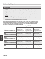
Size of joint pipes for indoor unit
Gas side
Capacity
of indoor
unit (A)
Size of main pipe(mm)
Liquid side
Φ12.7(0.5”)
Φ15.9(0.626”)
Φ15.9(0.626”)
Φ6.35(0.25”)
Φ9.5(0.375”)
Φ9.5(0.375”)
18K
24K
30K
Size of joint pipes for 410A indoor unit
Table 7.3
JOINT IN 01 2P
JOINT IN 01 2P
JOINT IN 01 2P
Available
branching pipe
Size of joint pipes for outdoor unit
Base on the following tables, select the diameters
of the outdoor unit connective pipes. In case of the
main accessory pipe large than the main pipe, take
the large one for the selection.
Model Gas side Liquid side
Φ15.9(0.626”)
Φ15.9(0.626”)
Φ15.9(0.626”)
Φ9.5(0.375”)
Φ9.5(0.375”)
Φ9.5(0.375”)
the size of main pipe(mm)
36K
48K
60K
Size of joint pipes for 410A outdoor unit
Table 7.4
The 1st branching pipe
JOINT IN 01 2P
JOINT IN 01 2P
JOINT IN 01 2P
Page 20
Page is loading ...
Page is loading ...
Page is loading ...
Page is loading ...
Page is loading ...
Page is loading ...
Page is loading ...
Page is loading ...
Page is loading ...
Page is loading ...
Page is loading ...
Page is loading ...
Page is loading ...
Page is loading ...
Page is loading ...
Page is loading ...
Page is loading ...
-
 1
1
-
 2
2
-
 3
3
-
 4
4
-
 5
5
-
 6
6
-
 7
7
-
 8
8
-
 9
9
-
 10
10
-
 11
11
-
 12
12
-
 13
13
-
 14
14
-
 15
15
-
 16
16
-
 17
17
-
 18
18
-
 19
19
-
 20
20
-
 21
21
-
 22
22
-
 23
23
-
 24
24
-
 25
25
-
 26
26
-
 27
27
-
 28
28
-
 29
29
-
 30
30
-
 31
31
-
 32
32
-
 33
33
-
 34
34
-
 35
35
-
 36
36
-
 37
37


SystemAir SYSPLIT DUCT 24 LNS HP Q Owner's manual
- Category
- Split-system air conditioners
- Type
- Owner's manual
Ask a question and I''ll find the answer in the document
Finding information in a document is now easier with AI
Related papers

Other documents
-
 AlpicAir AWI-26HRDC1TB User manual
-
Hisense R32 User manual
-
Cooper & Hunter CH-M09DTUI Installation guide
-
 AlpicAir AWO-54HRDC1C User manual
-
 Kaisai KCA3U-12HRF47 Installation guide
-
 Kaisai KCD-36HRF47 Installation guide
-
Keystone KSTAW08INV-HC User manual
-
-
Klimaire KDIS060-H2G1 Installation guide
-
 Opal A007-05C User manual


