Page is loading ...

NTI AG / LinMot Dok-Nr. 0185-0121-E_1V0_IG_Linear_Rotary_Motors_PR01-70-SSC
Installation Guide
Linear Rotary Motors
ENG
PR01-70-SSC

Installation Guide Linear Rotary Motors ENG
Page 2 / 60 PR01-70-SSC NTI AG / LinMot
Content
1 General Information ................................................................................................................................. 5
1.1 Introduction ........................................................................................................................................ 5
1.2 Explanation of Symbols ..................................................................................................................... 5
1.3 Qualified Personnel ........................................................................................................................... 5
1.4 Liability ............................................................................................................................................... 5
1.5 Copyright............................................................................................................................................ 5
2 Safety Instructions ................................................................................................................................... 6
3 Intended Use ............................................................................................................................................. 8
3.1 Linear Rotary Motor ........................................................................................................................... 8
3.2 Stainless Steel Front Flange (SSC) ................................................................................................... 8
3.3 Internal Mechanical Stops ................................................................................................................. 9
3.4 Max. Speed ........................................................................................................................................ 9
3.5 Pneumatic Brake ............................................................................................................................... 9
4 Installation Instructions ........................................................................................................................... 9
4.1 Operating Conditions ......................................................................................................................... 9
4.2 Installation Options ............................................................................................................................ 9
4.2.1 Vertical Installation ....................................................................................................................... 10
4.2.2 Horizontal installation ................................................................................................................... 12
4.3 Mounting the Load on the Shaft ...................................................................................................... 13
4.3.1 Shaft-Hub Clamping .................................................................................................................... 13
4.4 Material Data ................................................................................................................................... 13
5 Connections ............................................................................................................................................ 14
5.1 Motor Cable ..................................................................................................................................... 14
5.1.1 Technical Data ............................................................................................................................. 14
5.1.2 Rotatability of Motor Connector ................................................................................................... 14
5.2 Connector Wiring Linear Motor ........................................................................................................ 15
5.3 Connector Wiring Rotary Motor ....................................................................................................... 15
5.4 Connecting the Drive to the Motor ................................................................................................... 16
5.5 Pneumatic Air Connection ............................................................................................................... 16
6 Start-up .................................................................................................................................................... 17
6.1 Linear Motor and Rotary Motor ........................................................................................................ 17
6.2 Default Values of the Coordinate System ........................................................................................ 17
6.2.1 Angle of Rotation ......................................................................................................................... 17
6.2.2 Position ........................................................................................................................................ 17
6.3 Plug and Play Function for Linear Rotary Motors ............................................................................ 17
6.4 Setting Motor Parameters ................................................................................................................ 18
6.4.1 Selection of the Motor Data Files................................................................................................. 18
6.4.2 Application-specific Parameters .................................................................................................. 18
6.4.3 Inverting the Coordinate System ................................................................................................. 18
6.4.4 Selection of the Linear and Rotary Unit System .......................................................................... 20
6.4.5 Referencing the Linear Motor ...................................................................................................... 20
6.4.6 Referencing the Rotary Motor ...................................................................................................... 21

Installation Guide Linear Rotary Motors ENG
NTI AG / LinMot PR01-70-SSC Page 3 / 60
7 Accessories ............................................................................................................................................ 22
7.1 Overview .......................................................................................................................................... 22
7.2 Motor Cable ..................................................................................................................................... 23
7.2.1 Linear Motor / Rotary Motor ......................................................................................................... 23
7.3 Fan Kit .............................................................................................................................................. 24
7.4 Mounting Flanges for Linear Motor .................................................................................................. 24
7.5 Cooling Profile for Linear Motor ....................................................................................................... 25
7.6 Shaft-Hub Clamping ........................................................................................................................ 25
7.6.1 Dimensions and Technical Data .................................................................................................. 26
7.6.2 Mounting ...................................................................................................................................... 26
7.7 Wiper ................................................................................................................................................ 26
7.8 Magnetic Spring «MagSpring®» Kit UNO ....................................................................................... 27
7.8.1 Overview ...................................................................................................................................... 27
7.8.2 Dimensions and Technical Data .................................................................................................. 28
7.9 Magnetic Spring «MagSpring®» Kit UNO 30° ................................................................................. 30
7.9.1 Overview ...................................................................................................................................... 30
7.9.2 Dimensions and Technical Data .................................................................................................. 31
7.10 Magnetic Spring «MagSpring®» Kit DUO ....................................................................................... 33
7.10.1 Overview .................................................................................................................................. 33
7.10.2 Dimensions and Technical Data .............................................................................................. 34
7.11 Magnetic Spring «MagSpring®» Kit SYM........................................................................................ 36
7.11.1 Overview .................................................................................................................................. 36
7.11.2 Dimensions and Technical Data .............................................................................................. 37
7.12 MagSpring Kit Mounting Orientation ................................................................................................ 39
7.13 Direction of Force MagSpring Kit ..................................................................................................... 40
7.14 Holding Brake Kit ............................................................................................................................. 40
7.14.1 Overview .................................................................................................................................. 41
7.14.2 Dimensions and Technical Data .............................................................................................. 42
7.14.3 Holding Brake Kit Mounting Orientation .................................................................................. 43
7.15 Cam Kit ............................................................................................................................................ 44
7.15.1 Overview .................................................................................................................................. 44
7.15.2 Dimensions and Technical Data .............................................................................................. 45
8 Maintenance and Test Instructions ...................................................................................................... 46
8.1 Maintenance .................................................................................................................................... 46
8.2 Inspection......................................................................................................................................... 47
8.3 Maintenance Instructions ................................................................................................................. 48
8.3.1 Cleaning the visible Part of the Slider .......................................................................................... 48
8.3.2 Cleaning the Inside of the Linear Motor ....................................................................................... 49
8.4 Full Maintenance ............................................................................................................................. 51
8.4.1 Linear Ball Bearing / Plain Bearing .............................................................................................. 51
8.4.2 Ball Bearing .................................................................................................................................. 51
8.4.3 Air Coupling / Rotary Coupling (Hollow Slider) ............................................................................ 51
8.5 Cleaning Agents / Lubricants ........................................................................................................... 52

Installation Guide Linear Rotary Motors ENG
Page 4 / 60 PR01-70-SSC NTI AG / LinMot
8.6 Electrical Resistance Test ............................................................................................................... 53
8.6.1 Linearmotor PS01–48x240F-C .................................................................................................... 53
8.6.2 Drehmotor-Stator RS01-70x100-C .............................................................................................. 53
9 Transport and Storage ........................................................................................................................... 53
10 Dimensions......................................................................................................................................... 54
10.1 PR01-70x100-SSC-C/48x240F-C-150 (L) ....................................................................................... 54
11 International Certificates ................................................................................................................... 55
12 EU Declaration of Conformity CE-Marking ..................................................................................... 58
13 UK Declaration of Conformity UKCA-Marking ................................................................................ 59

Installation Guide Linear Rotary Motors ENG
NTI AG / LinMot PR01-70-SSC Page 5 / 60
1 General Information
1.1 Introduction
This manual includes instructions for the assembly, installation, maintenance, transport, and storage of linear
rotary motors. The document is intended for electricians, mechanics, service technicians, and warehouse
staff.
Read this manual before using the product and observe the general safety instructions and those in the
relevant section at all times.
Keep these operating instructions in an accessible place and make them available to the personnel
assigned.
1.2 Explanation of Symbols
Triangular warning signs warn of danger.
Round command symbols tell what to do.
1.3 Qualified Personnel
All work such as installation, commissioning, operation and service of the product may only be carried out by
qualified personnel.
The personnel must have the necessary qualifications for the corresponding activity and be familiar with the
installation, commissioning, operation and service of the product. The manual and in particular the safety
instructions must be carefully read, understood and observed.
1.4 Liability
NTI AG (as manufacturer of LinMot and MagSpring products) excludes all liability for damages and
expenses caused by incorrect use of the products. This also applies to false applications, which are caused
by NTI AG's own data and notes, for example in the course of sales, support or application activities. It is the
responsibility of the user to check the data and information provided by NTI AG for correct applicability in
terms of safety. In addition, the entire responsibility for safety-related product functionality lies exclusively
with the user.Product warranties are void if products are used with stators, sliders, servo drives or cables not
manufactured by NTI AG unless such use was specifically approved by NTI AG.
NTI AG’s warranty is limited to repair or replacement as stated in our standard warranty policy as described
in our "terms and conditions" previously supplied to the purchaser of our equipment (please request copy of
same if not otherwise available). Further reference is made to our general terms and conditions.
1.5 Copyright
This work is protected by copyright.
Under the copyright laws, this publication may not be reproduced or transmitted in any form, electronic or
mechanical, including photocopying, recording, microfilm, storing in an information retrieval system, not even
for training purposes, or translating, in whole or in part, without the prior written consent of NTI AG.
LinMot® is a registered trademark of NTI AG.

Installation Guide Linear Rotary Motors ENG
Page 6 / 60 PR01-70-SSC NTI AG / LinMot
2 Safety Instructions
Pacemaker / Implanted heart defibrillator
Sliders could affect the functioning of pacemakers and implanted heart defibrillators. For the
duration of a strong approach to a magnetic field, these devices switch into test mode and
will not function properly.
• If you wear one of those devices keep a minimum distance of 300 mm (12ʺ) between
the pacemaker / defibrillator and the housing of the linear rotary motor.
• Inform others who wear these devices to comply with this minimum distance!
Caution - Risk of Electric Shock !
Before working, make sure that there are no high voltages.
Fast-moving machine parts
The sliders of LinMot linear motors are fast-moving machine parts. All necessary
precautions must be taken to prevent persons approaching the moving elements during
operation (provide covers, guards, etc.).
Automatic restart
The motors can start automatically under certain cricumstances!
If necessary, a corresponding warning symbol must be provided and protection against
entering the hazardous area or a suitable safe electronic disconnection must be provided!
Risk of injury due to a defect or fault
For areas where a defect or fault can result in substantial property damage or even serious
personal injury, additional external precautions must be taken or devices must be installed
to ensure safe operation even if a defect or fault occurs (eg. suitable safe electronic
disconnection, mechanical interlocks, barriers, etc.).
Magnetic field
Magnets integrated in the sliders produce a strong magnetic field. They could damage TVs,
laptops, computer hard drives, credit and ATM cards, data storage media, mechanical
watches, hearing aids, and speakers.
• Keep magnets away from devices and objects that could be damaged by strong
magnetic fields.
• For the above mentioned objects, keep a minimum distance as described in the
"Pacemaker / implanted defibrillator" section.
• For non-anti-magnetic watches, keep the double minimum distance.
Burn hazard
The shaft of LinMot linear rotary motors can reach temperatures of 80 °C, which may cause
burns upon contact.
Grounding
All metal parts that are exposed to contact during any user operation or servicing and likely
to become energized shall be reliably connected to the means for grounding.

Installation Guide Linear Rotary Motors ENG
NTI AG / LinMot PR01-70-SSC Page 7 / 60
Effects on people
According to the current level of knowledge, magnetic fields of permanent magnets do not
have a measurable positive or negative effect on people. It is unlikely that permanent
magnets constitute a health risk, but it cannot be ruled out entirely.
• For your own safety, avoid constant contact with magnets.
• Store large magnets at least one meter away from your body.
Temperature resistance
Keep motors away from unshielded flame or heat.
Temperature above 120°C will cause demagnetization.

Installation Guide Linear Rotary Motors ENG
Page 8 / 60 PR01-70-SSC NTI AG / LinMot
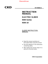
3 Intended Use
3.1 Linear Rotary Motor
1: Linear rotary shaft
2: Stainless steel front
flange
2: Stator (rotary motor)
3: Stator (linear motor)
4: Slider linear motor
The PR01 linear rotary motors are electric direct drives for use in industrial and commercial installations. For
correct handling, observe the warnings listed in chapter 2.
The PR01 linear rotary motor is designed for simultaneous linear and rotating movements. This means that
the rotary and linear movements can be performed simultaneously and completely independently of each
other. If the application allows it, it is recommended to perform the rotary motion with the linear rotary shaft
retracted. The rotary and linear movements should also be carried out one after the other if possible. This
reduces the bearing loads and increases the service life of the bearings.
3.2 Stainless Steel Front Flange (SSC)
The stainless steel front flange offers the user hygiene at the highest level. Linear rotary motors with a
stainless steel front flange can be used in machines and systems for processing food products or in the
pharmaceutical and medical industries. With this, the user benefits from a partially increased IP degree of
protection as well as the possibility to use the front of the linear rotary motor even in extremely rough or
corrosive environments where aggressive cleaning agents are used.
• The IP degree of protection of the stainless steel front reaches IP67. The remaining part
of the linear rotary motor achieves a reduced IP degree of protection IP64.
• The exact list of materials used can be found in chapter 4.4.
• The user is obliged to check whether the cleaning agents used are compatible with the
materials of the stainless steel front flange.
• The stainless steel front flange may only be cleaned when the axle is at a standstill. It is
recommended that cleaning is carried out with the linear rotary shaft extended.
The linear rotary shaft must be dried before it is put back into operation.
• Any parts that do not belong to the zone of the stainless steel front flange may not be
corrosion-resistant and can therefore only be cleaned to a limited extent. They have a
reduced IP degree of protection.
• The specified IP degree of protection is achieved at standstill.

Installation Guide Linear Rotary Motors ENG
NTI AG / LinMot PR01-70-SSC Page 9 / 60
3.3 Internal Mechanical Stops
Do not drive into the internal mechanical stops!
It must be ensured that the linear motor does not move to the lower or upper internal stop
during operation, as otherwise the linear motor may be damaged! The internal stops may
only be used for homing purposes. The homing speed must not exceed the value of 0.01
m/s.
3.4 Max. Speed
The mechanically maximum permissible speed of 1000 rpm must not be exceeded.
3.5 Pneumatic Brake
As an option, a brake can be attached to the linear motor. The pneumatic brake is controlled by the servo
drive. To open and close the brake, an additional electric solenoid valve is required. The brake acts on the
shaft arranged parallel to the rotor and is released by compressed air.
• The brake has a purely holding function and is not designed to slow down or stop
dynamic movements.
• Not to be used for safety devices!
• Not approved as a safety element!
4 Installation Instructions
4.1 Operating Conditions
Maximum ambient temperature limits:
• -10 °C…80 °C
Internal temperature sensor error occurs at:
• 90 °C
Max. Installation altitude
• The maximum installation altitude is 4,000 m above sea level.
From 1,000 m upwards, a derating of 1 °C per 100 m must be taken into account for air
cooling.
4.2 Installation Options
The PR01 linear rotary motors have a centric fit on the front side, so that an exact alignment of the rotation
axis is possible.
Mounting only via the front screws is generally not sufficient (vibrations, transverse load) and must be
supplemented by an additional support. For vibration reasons, a support as far back as possible is
preferable. See the mounting examples in the following chapter. Please note that a tolerance compensation

Installation Guide Linear Rotary Motors ENG
Page 10 / 60 PR01-70-SSC NTI AG / LinMot
(see next chapter) must be provided so that the motor is not installed in the machine under tension. The
detailed mounting dimensions can be found in chapter 10 "Dimensions". The corresponding CAD files are
available in the LinMot eCatalog https://shop.linmot.com/
4.2.1 Vertical Installation
Support via lateral surface on the rotary motor
In order to avoid overdetermination of
the different motor bearings, the
support must have a minimum
clearance. This compensates for any
tolerances in the linear rotary motor.
Support via angle and cooling flange of the
linear motor
In order to avoid overdetermination of
the different motor bearings, the
support must have a minimum
clearance. This compensates for any
tolerances in the linear rotary motor.

Installation Guide Linear Rotary Motors ENG
NTI AG / LinMot PR01-70-SSC Page 11 / 60
Support via lateral bracing on the cooling flange
of the linear motor
In order to avoid overdetermination of
the different motor bearings, the
support must have a minimum
clearance. This compensates for any
tolerances in the linear rotary motor.
Support via lateral bracing at the end of the
linear motor
In order to avoid overdetermination of
the different motor bearings, the
support must have a minimum
clearance. This compensates for any
tolerances in the linear rotary motor.

Installation Guide Linear Rotary Motors ENG
Page 12 / 60 PR01-70-SSC NTI AG / LinMot
Support via lateral bracing on the multi-function
flange
In order to avoid overdetermination of
the different motor bearings, the
support must have a minimum
clearance. This compensates for any
tolerances in the linear rotary motor.
4.2.2 Horizontal installation
Attachment to lower surface on rotary motor
If the lower mounting holes are used, tolerance
compensation with a washer should be provided.

Installation Guide Linear Rotary Motors ENG
NTI AG / LinMot PR01-70-SSC Page 13 / 60
4.3 Mounting the Load on the Shaft
The assembly and disassembly of the load mass must not take place in the mechanical end
stops of the linear movement. An external support must be used.
4.3.1 Shaft-Hub Clamping
The shaft-hub clamping is a non-positive
connection which is produced by means of two
conical rings.
The use of drivers or the production of grooves is
completely eliminated. The suitable shaft-hub
clamping type can be ordered from LinMot.
Mounting instructions and ordering information can
be found in the "Accessories" chapter.
4.4 Material Data
Component
Material
Linear rotary shaft
Stainless Steel Mat. 1.4404 / 316 L (hardened)
Front flange (Rotary motor)
Stainless Steel Mat. 1.4404 / 316 L
Housing (Rotary motor)
Anodized Aluminum
Wiper (Front flange)
HPU
Plain bearing (Front flange)
HPV PPS Food Grade

Installation Guide Linear Rotary Motors ENG
Page 14 / 60 PR01-70-SSC NTI AG / LinMot
5 Connections
5.1 Motor Cable
Only connect or disconnect the motor connector and sensor cable if no voltage is applied to
the servo drive! Only original LinMot cables may be used for wiring the motor and sensor!
Even assembled cables may only be manufactured from the original LinMot components
and must be checked carefully before commissioning!
Incorrect motor wiring can damage the motor and/or the servo drive!
5.1.1 Technical Data
Wiring Linear Rotary Motor
Cable type
Standard cable
High-flex cable
Robot cable
Cable name
K15-04/05
KS10-04/05
KR10-04/05
Min. bending radius
stationary
50 mm (2 in)
50 mm (2 in)
50 mm (2 in)
Min. bending radius
moving
Not suitable for
applications with moving
motor cable
100 mm (4 in)
No torsion
100 mm (4 in)
Max. torsion:
±270° pro 0.5 m
Approval
UL / CSA 300V
E467697
UL / CSA 300V
E172204
UL / CSA 300V
E172204
Material wire insulation
TPE-U
TPE-E
TPE-E
Material cable sheath
PUR
PUR
PUR
Oil resistance
very good
very good
very good
Chemical resistance (to
acids, alkalis, solvents,
hydraulic fluid)
good
good
good
Outdoor durability
very good
very good
very good
Flammability
flame retardant
flame retardant
flame retardant
5.1.2 Rotatability of Motor Connector
The motor connectors of the linear motor (C-connector) and the rotary motor (C-connector) can be turned by
hand in both directions (see illustration below). The maximum angle of rotation for the C connector is 330°.

Installation Guide Linear Rotary Motors ENG
NTI AG / LinMot PR01-70-SSC Page 15 / 60
5.2 Connector Wiring Linear Motor
View: Motor connector, plug side
Connector wiring
Linear Motor:
C-Connector
Wire colour
Motor cable
Ph 1+ / Ph A
A
red
Ph 1- / Ph B
B
pink
Ph 2+ / Ph C
C
blue
Ph 2- / Ph D
D
grey
+5VDC
E
white
GND
F
inner shield
Sin
G
yellow
Cos
H
green
Temp.
L
black
Shield
Housing
outer shield
5.3 Connector Wiring Rotary Motor
View: Motor connector, plug side
Connector wiring
Rotary Motor:
C-Connector
Wire colour
Motor cable
Ph 1+ / Ph A
A
red
Ph 1- / Ph B
B
pink
Ph 2+ / Ph C
C
blue
Ph 2- / Ph D
D (not connected)
grey
+5VDC
E
white
GND
F
inner shield
Sin
G
yellow
Cos
H
green
Temp.
L
black
Shield
Housing
outer shield
Motor extension cables are double shielded. The two shields of the extension cable are
insulated from each other. The inner shield of the extension cable may only be connected to
GND (no contact to the outer shield).
The outer shield must be connected to the shield of the connector.

Installation Guide Linear Rotary Motors ENG
Page 16 / 60 PR01-70-SSC NTI AG / LinMot
5.4 Connecting the Drive to the Motor
The following diagram shows the connection of the linear motor with the LinMot Drive.
5.5 Pneumatic Air Connection
All linear rotary motors of the size PR01-70-SSC are optionally available in a hollow shaft L-version. This
motor type has a through bore of Ø 4 mm, which passes through the rotor and the rotary shaft. This enables
the user to implement pneumatic applications with an operating pressure of max. 6 bar. In the case of a
vacuum application, it is recommended to use a unit with sufficient power, since experience has shown that
any air coupling points generate minor losses.
The specifications of the connections are shown in the drawing above.
G1/8 x 8
G1/4 x 8

Installation Guide Linear Rotary Motors ENG
NTI AG / LinMot PR01-70-SSC Page 17 / 60
6 Start-up
6.1 Linear Motor and Rotary Motor
Linear motor and rotary motor are electrically independent units. The commissioning of the linear motor can
therefore be performed sequentially. It does not matter which motor (linear motor or rotary motor) is
commissioned first.
The various parameters for the linear motor and the rotary motor are set on the drive side via the Motor
Wizard in the LinMot Talk configuration program.
Do not drive into the internal mechanical stops!
It must be ensured that the linear motor does not move to the internal stop during operation
under any circumstances, as otherwise the linear motor may be damaged! The internal
stops may be used for the purpose of homing, but the homing speed must not exceed 0.01
m/s.
6.2 Default Values of the Coordinate System
6.2.1 Angle of Rotation
Looking into the shaft, the positive
counterclockwise counting direction of the angle of
rotation is defined.
6.2.2 Position
With regard to the motor, the positive counting
direction of the position is defined by retracting the
stroke rotary shaft.
To invert the coordinate system you will find detailed information in chapter 6.4.3.
6.3 Plug and Play Function for Linear Rotary Motors
LinMot linear rotary motors of the latest generation are Plug and Play capable (see motor label "PnP"). This
means that they register with the drive independently. The module- and motor-specific parameters are
automatically stored in the drive and the motor is ready for operation.
Application-specific parameters, such as cable length, load mass, PID control settings etc. can be entered by
the user using the Motor Wizard.
To do this, click on the Motor Wizard symbol in the task bar of the LinMot-Talk software.
Then follow the sequence of steps from chapter 6.4.2.

Installation Guide Linear Rotary Motors ENG
Page 18 / 60 PR01-70-SSC NTI AG / LinMot
6.4 Setting Motor Parameters
The various parameters for the linear motor and the rotary motor are set via the corresponding motor wizard
in the LinMot Talk configuration program. To open the wizard, select the "Motor Wizard" icon in the task bar.
6.4.1 Selection of the Motor Data Files
If the connected motor is a module with plug and play functionality, the following step can be skipped.
If no "PnP" symbol is printed on the motor nameplate, the module and motor-specific parameters must be
loaded manually via the Motor Wizard. So-called motor data files are available for this purpose. The motor
data file corresponding to the module (*.adf or *.adp) must be selected in the first step of the Motor Wizard.
The linear rotary motors are located in the installation directory of the LinMot-Talk software (download at
www.linmot.com) in the folder "Motors\LinMot Linear Rotary Motors\...".
Please contact support if the motor data files are not available.
6.4.2 Application-specific Parameters
Application-specific parameters, such as cable length, load mass, PID control settings, etc. can be entered
by the user using the Motor Wizard. The Motor Wizard must be started for this purpose. Once the Motor
Datafile has been selected (according to the previous chapter), the Motor Wizard guides you through the
menu step by step.
Application parameters should be entered as accurately as possible to ensure the best possible motor
control.
6.4.3 Inverting the Coordinate System
Starting with LinMot-Talk version 6.8 the direction of the coordinate system can be selected.
Default value for rotary motors: Positive counting direction = counterclockwise (see figure chapter 6.2.1)
Default value for linear motors: Positive direction of movement = Regular (see figure in chapter 6.2.2)
If the coordinate system is reversed, this has an influence on the current and the
force/torque of the motor. In case of any uncertainties, the LinMot support should definitely
be contacted.

Installation Guide Linear Rotary Motors ENG
NTI AG / LinMot PR01-70-SSC Page 19 / 60
Figure: Selection of the positive counting direction (rotary motor)
Figure: Selection of the positive direction of movement (linear motor)

Installation Guide Linear Rotary Motors ENG
Page 20 / 60 PR01-70-SSC NTI AG / LinMot
6.4.4 Selection of the Linear and Rotary Unit System
In step 4 of the Motor Wizard the GUI (Graphical User Interface) of the LinMot-Talk software can be set. This
setting only affects the display of the LinMot-Talk software. The resolution and scaling of the transmission
data (raw data) to the higher-level PLC are retained.
Figure: Selection of the units to be displayed in the LinMot-Talk software
6.4.5 Referencing the Linear Motor
The built-in linear motor has a position detection system which must be referenced. Various modes are
available to the user for this purpose. Depending on the selected mode, the linear motor searches for a
mechanical stop and/or an electronic switch, for example.
Figure: Selection of reference run linear motor
/