Page is loading ...

ACE INDUSTRIAL
PRODUGTS
PORTABLE
AIR
GLEANER
MODEL
73-250
INSTRUGTION
&
MAINTENANCE
MANUAL
CAUTION:
This device is
powered
by rotating
elect cal
machinery!! Careless
or
improper
use
may result
In
personal
injury.
Read the Safety
Precautions
ancl Warnings
contained
within
plig!
to operating
this
machine
READ
AND SAVE
THESE
INSTRUCTIONS.
cAUTION:
(AIRFLOW
BLOCKAGE)
Since exhaust
air
teaves the
bottom
of this unit,
caution should
be
obseNed
not to
set unit
down
in
such a
way as to
block the
exhaust
MISCELLANEOUS
GAUTIONS:
1. Use of any
attachment
not recommended
or
sold by
the air cleaner
manufacturer
may result
in risk of
fire. eleciric
shock,
or
injury
to
persons
2.
To reduce the
risk
ofdamage
to the
elect
cplug
orcord, disconnect
by
pulling
plug
ratherthan
cod when
rcmoving
power
from
the
air
cleaner'
3.
I\rake sure
cord
and hose
are
located
so they
will not
be stepPed
on,
tripped
over'
oa otnerwise
subjected
to
damage
or stress
4. An
extension
cord
should
not be
used
unless
absolutelv
necessary.
Use
of
improper
extensio; cord could
result
in risk offire
and
etectric
shock.
lf extens;on
cord
must
be used'
use only
a
grounded cord and
follow
lhese
rccommendations:
25
ft.
-#14
AWG.
50
ft.
-
#1
2 AWG
100 ft.
-#10
AWG.
5- Do
not disassemble
the
air cleaner.
Takeittoa
qualified
seNiceman
when
seryice
or
repalr
ls
;quired,
incorrect
reassembly
may
result
in risk
ot electric
shock
or fire-
6.
To reduc€
the
risk of
electric
shock
or bodily
injury, unplug
the aircleanerfrom
outlet
before
attempting
any
maintenance
or cEanlng
Turning
off the
power
switch
will
not eliminate
this
risk.
SAFETY
WARNINGS
&
CAUTIONS
FAILURE TO OBSERVE
THE FOLLOWING
PRECAUTIONS
COULD
RESULT
IN SERIOUS
INJURY,
INCLUDING
DEATH IN
EXTREME
CASES, SAVE
THESE
INSTRUCTIONS.
WARNING:
(EXPLoSION HAZARD)
This unit
contains unive6al
motors,
which spark
during
normal operation.
Do
not use
in areas
contaminated
by
volatile or
flammable
materials
as
these sparks
may ignite
the contaminates
and cause
a dangerous
explosion.
WARNING:
(HARMFUL FUMES)
The filters
used in this
unitwill
remove
solid
padiculate
ONLY,
and do
not eliminate
fumes
and
gases
that may
be a health
hazard
Failure
to
observe
the
presence
of such
fumes
could
cause
serious
illness or
death.
CAUTION:
(SHOCK
HAZARD)
To insure
continued
protection against
shock
hazard, connect
AC cord
only to
pfoperly
gfounded
outtets.
Reolace defective
cords
immediately
Do
not expose
to moisture
or liquid
as
this could
defeat
the electrical
insulation
thus
causing
electrical
snocK.
CAUTION:
(STRONG
VACUUM)
Care must
be taken to
avoid
personal
injury by
not
allowing
hose inlet
to contact
any
body area
such as
eyes,
ears,
mouth, etc.
CAUTION:
(LIFTING)
Although
this unit weighs
less than
40
lbs w,th
filiers,
improper lifting
or handling
ofthis
unit could
cause
back injury.
Follow the
recommended
method
for lifting.

THEORY
OF OPERATION
This
unit
is a lightweight,
portable
air
cleaner
ernploying
two thermally
protected, high
performance,
flow thrcugh
vacuum
molors
producing
very high
velocity
arrflow
through
the
unit
'By
utilizing
a large
(2
%")
inlet
plus
a variety
of
collectrng
nozzles and
fittings
flne
solid
padiculate
maierial;nd smoke
maY
be
removed
from
the air
by
the
filter media.
An initial
spark trap
collects
large
partioles
before
thev
reach the
filter. An
easy to
emPty
tray
is
attachecl
to the
front cover
to enable
the
removal
of
lhe
larqe
garticles
collected
by
the spark
trap
without
removing
the
filter. This
tap
further
isolates
the
filter
from sparks
in the
case
of a weld,ng
operatlon.
A"cloooed" fllter
liqht.
actuated
by a
d ferential
oress;;
switch
is-an
integral
part
ofthe
unit
When
ihe filters
becote
clogged,
the
light
will
illuminate'
At
this
point,
the filter
should
be
changed
GENERAL
MAINTENANCE
ONLY QUALIFIED
SERVICE
TECHNICIANS
SHOULD
MAKE
REPAIRS
TO
THIS UNIT'
DO NOT
REPLACE
THESE
MOTORS
WITH
MOTORS
OTHER
THAN
THOSE
RECOMMENDED
BY THE
MANUFACTURER,
UNPACKING
Carefully
inspect the
unit
for concealed
damage
that
mav
have occuned
during
shipping
and
handling
lf
ani
damage
is found,
immediately
contact
the
Fr;ioht comoanv.
Make
sure
there
are
no dents
in
the
iousing,
as they
might
prevent
the
filter
from
sliding
into the unit
smoolhly
lf there
is
no
evidence
of da;aqe,
remove the
end
cover
by
releasing
the
two rubGr
latches.
Removal
of
the
front cover
will
allow
inspection
of
the inside
of
the
unit
After
unpacking
the
machine,
check
to
see
that the
following
parts
and
accessories
are
presenl:
1)
-
10'Flexible
Hose
1)
-
Coupling
1i
-
Flexibbtetal
Hose/Magnetic
Base
comPonent
Parts.
(See
Figlre
#2
For Individual
Parts
Included)
1)
-
Slot
Nozzle
1)
-
Filter
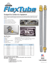
INSTALLATION
(See
Fisure
#1)
1.
lnsert the
filter,
gasketfrrst,
into the
unit. Then
Dlace the rubberthen
steelwashers
over the
threaded
rod. Tighten
the
wing
nut down
so that
the filter
is sealed
and
will not
rotate.
2. Reolace
the front
cover/spark
trap
assembly
and
re-iatch
the cover
using
the
rubber
latches.
3. Connect
the unit
to the
power
source
and
test
the
operation
of
the unit
by
turning
it ON
with the
On/Off switch.
Should
the
motors
not
start, or
should the
machine
make
unusual
noises'
immediatelv
turn
the
machine
off
and
seek
trained
maintenance
personnel.
Once
the
test is
complete,
turn
the unit
back
OFF
4. Attach
the
hose
to the
inlet
5. Assemble
the flexible
metal
hose
and
nozzle
per
Figure
#2.
6 Connect the
hose/nozzle
comolnatlon
assembled
in Step
5 above
to the
machinewith
the
10'flexible
hose
and
the
supplied
coupling
This comDletes
the
basic assembly
ofthe
unit
Deoendinq
upon
the
accessories
ordered
and
the
looistica
oithe
wo*
place,
lhe
installation
oo'nfiguration
maY vary.

Figure I
Figure
2
OPERATION
Your
ACE
Industial Producls
machine
is designed
as a
source
caolure
device,
i.e., il is
inlended
to eliminale
smoke
and
partrculale
at theit
point ol origin
Keeping this
jn
mind, the
machine should
be operated
in the
following
Re-read the
section on
Safety
Wamings
& Caulions
before
prcceeding any turther.
1. Place
lhe machine
on a flat,
level
surface
Pick a
location that
will allo"v
unrestricted
flow of the
exhausl
air to
lh€ atmosphere.
2.
For units wilh
wheels or
casters,
lock lhe
wheels or
block
lhe wheels.
3. Place
lhe coltection
nozzle
as close
to the wolft
as
practical
without
intedering
wilh the
operator. Sec|lrc
the nozzle
if necessary.
lJsinothe
ON/OFF
switch,
tum
lhe machine
on
Should
the motor
not
start,
or should
the
machine
make unusualnoises.
immediately
lum he
machine
off and seek
trained
maintenance
personnel Do
nol
conlinue
to
use the
unit.
lJDon completion
ol the
speofic
manufacturing
or
w;bino
ooeralon,
tum
lhe
machine
ofl
Contnuous
runnin; oi|he unit
will
r€duce
the
litu ol lhe
frltet
and
the
mdtor brushes
as
well
as increase
utility
cosl
When lhe
"clogged'
filte. lighl
indicates
ihal
the
filter
is dogged,
tlm lhe
machine
off and
remove
power
cord
ftom its
Power
source
See the section
on
installation
and use
the
reverse
process
to remove
lhe
dirty
lillers
Re_inslall
the new
iilter and
reconnect
the
machine
to
its
power source'
MAINTENANCE
& REPLACEMENT
PARTS
FILTERS:
As oreviouslv stated
in lhe
Theory
of
Operation'
seclion
oitiris
r"nuit, ttte
"Aogged'lilter
indicator
light willlight
whenever the
dfierental
pressure
across
the
nller
incticates
lhat
lhe flter-rs
ctogged.
\ryhen
opening
the
unn'
there are no vacuum
hoses
to
disconnect
since
lhe
o.essure sensinq
is acaomplished
by
measunng
al the
inletand insid€the
suclion
chamber'
The drffetential
pressure ttip
poinl
is
preset
and
is not
field
adjuslable-
\ r'hen
the nlter
gets
dirty,
il needs to
be
€placed
wilh a
new one or
the-fitter
can
becleaned
Toclean
take
lhe
flter out
of lhe
unil. Hotd
the
flter 2 to
3 inches
above
a
concrete foor.
Gentiv
clrop
the fller.
Iotate
and
repeat unttl
mosl of the dirt
falls orn
of lhe
liller or
lhe
fher can
be
vacuumed
with a
Dortable
sh
vac
(lf
needed'
order
8G
201MD).
To re_assemble,
use
reverse
process fo
remove
flter and s\N€ep
up
dirt lhat
is on the
ioor'
q
6.

REPLACEMENT FILTER
CartddgeFilter........................................................65250
I.IAINTENANCE:
waB!!!g
MAINTENANCE ON THIS
UNIT SHOULD
BE
PERFORMED ONLY
BY
QUALIFIED,
TRAINED
TECHNICIANS.
1.
Motor brushes are available
from lhe
factory by
ordedng
Part No.65077.
The use ofhigh
perfo.mance,
ball sleeve
motors
provide
about 500
hours of brush
operation
(depending
upon
filter condilion).
Btushes
should b€
periodically
checked
after 500
hours use and
if
wom, replace as a matter
or
prevenlative
mainlenance.
2, Vacuum
Molors
are
available
from the
factory by
ordering
Part No. 65001 . These
motors are
thermally
protecled
by an aulomatic
resel thermal
circuil breaker
and will shut do\*n
if
they
are ovefpaled
due to
lack ot
airflow
or locked rctor condition.
DO I{OT REPLACE THESE
MOTORS WITH
A MOTOR
THAT DOES NOT
HAVE A THERMAL
OVERLOADI
REPAIR
PARTS
'1)
lvlotorWscrews-...........-
...................
. .
-
65001
2)[,lotorGasket..............-....................................65002
3)RubberLatch.-.......-..............-......
...
65003
4)
Clogged
Filter Indicalot
1i9h1............
.
.. . .. 65004
5) ON/OFF Toggle
Switch............
..
. .
65005
6)DifferentialPressureSwitch.....................
.65006
7) Motor brushes.....-.......-.............--....
..
-
...
65077
ACCESSORIES
The followiog accessories
and
attachments
are available
faom the factory or
fiom
yout
ACE dealer:
FlexTube.......
"
-
65012
MagnelicBase-...-....................
. ...-.-..-
.
65014
8" Diameter Round
Nozzle.
.. . .........-.........
..- .65015
4" Suction Cup
Base...-.......................
...
. . ... ...
65016
10' Extension Hose
& Coup|ing....
.. .
.. . ..
65017
3"Castert obilityKit...........-................-.......-.
. .65018
Stot Nozzle._...._..........................-
. .......................65019
20' Slol Nozzle
...........................
..-
.- . ..
. . . . 65036
Mobite Cart....._.._......-...-..........
. .. ......................--..
65038
'T' Adapter..................................
. ...
.. . ..
.. .. .65040
Reducer, 1-1/4'(Smoke
Exlractrng
Gun)-
.
-.
..65041
Reducer, 1-112'
(Smoke
Enracting
Gun) .
-
.. ..65043
PoweFMatic Induclive
switch
. .. ......
.. ...
.. 99-800
ACE INDUSTRIAL
PRODUCTS
A Division ofi
Associated Equlpment
Corporation
5043 Farlin
Avenue
St.
Louis, MO 63115
Tel.
(314)
3€t5178
Fax.
(314)
385'3254
SCHEi'ATIG WIRING
DIAGRAM
Figure
3
w2051
Rev.
0205 91
990009
/