When building in ceramic glass cooking areas the
front cross-rail of the build-in cupboard must be
removed in order to have the heat radiating off
escape without any obstacles.
The space under the hob unit must be closed at all
sides in a way that the lower side of the cooking
area is no longer accessible.
The distance from the hob to the furniture part
under the hob must at least amount to 20 mm. If
needed, please fix an insulation. Drawers must not
be located under a hotplate.
The distance from the hob to a high cupboard
beside right or left must at least amount 55 mm, to
the back wall at least amount 55 mm.
With regard to the protection against overheating of
surrounding furniture surfaces this appliance
corresponds to type Y (EN 60335). This appliance
or the built-in cupboard for the appliance
respectively may be located with the rear wall and
one side wall to whatever high walls or furniture
respectively and with the other side to another
appliance or furniture of the same height as this
appliance.
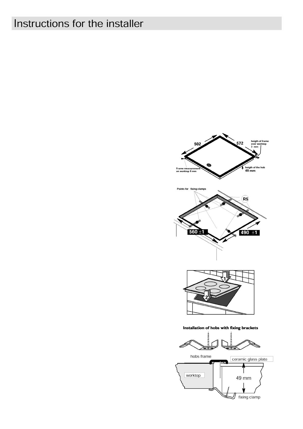
Built-in dimensions
The opening in the worktop must correspond to
commercial dimensions. The hints required are
given in the dimension sketch.
Built-in
Cut out the worktop acc. to prescribed cutout size.
The tolerance sizes must not be exceeded. Do
precisely saw at the mark line. Recommendation:
Mark the cut-out with a steel needle. Glue
something on the line in order to avoid shattering of
the coat when cutting.
With tile-coated worktop areas the slits in the
supporting area for the cooking area must be filled
up completely.
Clean the worktop in the cutout area.
From the top lay the cooking area into the cutout,
adjust concentrically and firmly press down.
Check the sealing in the supporting frame for
perfect seating and resting without a gap. Please
do not apply additional silicone sealing material,
the closure will make it harder to dismantle in case
of need for service, and may damage the worktop if
removing the hob.
5 holes in the bottom of the build-in case are
provided for the screws of the fitting plates.
At first screw on the fitting plates by a screwdriver
and afterwards regularly tighten the plates
alternatively and diagonally offset, until the frame of
the cooking area is perfectly laying on the worktop.
Over-tightening must be avoided! Electric
screwdrivers or pusher airscrews must be
exclusively used with slip clutch (setting value 1 --
1.1 Nm).
13


