English
IOM X 03-N-3GB
Part number / Code / Teil Nummer / Codice / Código : 3990529GB
Supersedes / Annule et remplace / Annulliert und ersetzt /
Annulla e sostituisce / Anula y sustituye : IOM X 03-N-2GB
Français EspañolDeutsch Italiano
Installation and maintenance manual
Manuel d’installation et de maintenance
Installations- und Wartungshandbuch
Manuale di installazione e di manutenzione
Manual de instalación y de mantenimiento
IOM X 03-N-3
Part number / Code / Teil Nummer / Codice / Código : 3990529
Supersedes / Annule et remplace / Annulliert und ersetzt /
Annulla e sostituisce / Anula y sustituye : IOM X 03-N-2
Packaged Air Conditioners
air cooled: X ARV water cooled: X AO
Centrales Autonomes de Climatisation
à condensation par air: X ARV à condensation par eau: X AO
Zentralklimageräte
luftkühlung: X ARV wasserkühlung: X AO
Centrali Autonome di Climatizzazione
con raffreddamento ad aria: X ARV con raffreddamento ad acqua: X AO
Centrales Autónomas de Climatisación
con condensación por aire: X ARV con condensación por agua: X AO
X
4650
6450
UC
74
104


INSTALLATION INSTRUCTION
NOTICE D’INSTALLATION
INSTALLATIONSHANDBUCH
ISTRUZIONI INSTALLAZIONE
INSTRUCCIONES DE INSTALACIÓN

CONTENTS
GENERAL RECOMMENDATIONS ...............................................................................................................3
SAFETY DIRECTIONS ................................................................................................................................................................ 3
WARNING ............................................................................................................................................................................... 3
EQUIPMENT SAFETY DATA ....................................................................................................................................................... 4
INSPECTION AND STORAGE .....................................................................................................................5
WARRANTY ...............................................................................................................................................5
CONTENTS OF PACKAGE ..........................................................................................................................6
DIMENSIONS ............................................................................................................................................6
NET WEIGHT ........................................................................................................................................................................... 6
TECHNICAL SPECIFICATIONS ....................................................................................................................7
POWER SUPPLY ........................................................................................................................................................................ 7
INTERCONNECTION WITH OUTDOOR UNIT (AIR COOLED UNIT) ........................................................................................... 7
DESCRIPTION ............................................................................................................................................ 8
INSTALLATION ..........................................................................................................................................9
INSTALLATION OF THE INDOOR UNIT ..................................................................................................................................... 9
CLEARANCE .............................................................................................................................................................................................. 9
UNIT LOCATION ....................................................................................................................................................................................... 9
AIR DISCHARGE AND INTAKE ................................................................................................................................................................... 10
ACCESS TO THE FILTERS .......................................................................................................................................................................... 10
INSTALLATION OF THE OUTDOOR UNIT................................................................................................................................ 11
CLEARANCES. .......................................................................................................................................................................................... 11
INSTALLATION. ........................................................................................................................................................................................ 11
ATTACHMENT TO THE GROUND ............................................................................................................................................................. 11
REFRIGERANT CONNECTIONS (AIR COOLED UNIT) ...............................................................................12
REFRIGERANT LINES ............................................................................................................................................................... 12
REFRIGERANT ........................................................................................................................................................................ 12
PIPES TO BE MADE ON SITE ................................................................................................................................................... 12
REFRIGERATION PIPE BENDING ............................................................................................................................................. 13
TIGHTENING TORQUE FOR REFRIGERANT VALVES ................................................................................................................. 13
FOLLOW THE CONNECTION INSTRUCTIONS FOR THE VALVES WITH NON-REMOVABLE MEMBRANES ................................... 13
HYDRAULIC CONNECTIONS ................................................................................................................... 14
SAFETY DRAIN. ...................................................................................................................................................................... 14
ELECTRICAL CONNECTIONS ................................................................................................................... 14
TRANSFORMER ...................................................................................................................................................................... 14
INTERCONNECTIONS ........................................................................................................................................................... 15
INTERCONNECTIONS WITH REMOTE CONTROL ................................................................................................................... 15
CONTROL PANEL ....................................................................................................................................16
2

POWER SUPPLY MUST BE
SWITCHED OFF
BEFORE STARTING WORK
IN THE ELECTRIC
CONTROL BOX
GENERAL RECOMMENDATIONS
Please read the following safety precautions very carefully before installing the unit.
SAFETY DIRECTIONS
Follow the safety rules in forces when you are working on your appliance.
The installation, commissioning and maintenance of these units should be performed by qualified personnel having
a good knowledge of standards and local regulations, as well as experience of this type of equipment.
The unit should be handled using lifting and handling equipment appropriate to the unit's size and weight.
Any wiring produced on site must comply with the corresponding national electrical regulations.
Make sure that the power supply and its frequency are adapted to the required electric current of operation, taking
into account specific conditions of the location and the current required for any other appliance connected to the
same circuit.
The unit must be EARTHED to avoid any risks caused by insulation defects.
It is forbidden to start any work on the electrical components if water or high humidity is present on the installation
site.
WARNING
Cutoff power supply before starting to work on the appliance.
When making the hydraulic connections, ensure that no impurities are introduced into the pipe work.
The manufacturer declines any responsibility and the warrantly becomes void if these instructions
are not respected.
If you meet a problem, please call the Technical Department of your area.
If possible, assemble the compulsory or optional accessories before placing the appliance on its final location. (see
instructions provided with each accessory).
In order to become fully familiar with the appliance, we suggest to read also our Technical Instructions.
-The informations contained in these Instructions are subject to modification without advance notice.
3

EQUIPMENT SAFETY DATA
Safety Data R407C
Toxicity Low
In contact with skin Liquid splashes or sprays may cause freeze burns. Unlikely to be hazardous by skin absorption.
However, R407C may be slightly irritant and, if liquid, it has a strong degreasing effect. Flush contaminated skin
areas with running water. If it comes into contact with wet fabrics, the liquid refrigerant will cause them to freeze
and adhere to the skin. Carefully remove the contaminated clothing since it might adhere to the skin and cause
freeze burns. Apply to a doctor if the affected skin areas should be reddened or irritated.
In contact with eyes Vapours have no effect. Liquid splashes or sprays may cause freeze burns. In these cases rinse your eyes with
running water or with a solution for eye lavages for at least 10 minutes. Immediately apply to a doctor.
Ingestion Very unlikely to occur. If this should be the case, it may cause freeze burns. Never induce vomiting.
Keep the patient awake. Make it rinse its mouth with running water and make it drink about 1/4 of a litre.
Immediately apply to a doctor.
Inhalation R407C: High concentration levels of its vapours in the air can produce an anaesthetic effect, including the loss of
consciousness. Particularly severe exposures may cause heart arrhythmia and sometimes prove to be also fatal.
At high concentrations there is a danger of asphyxia due to a reduced oxygen content in the atmosphere. In these
cases take the patient to the open air, in a cool place and keep it at rest. Administer oxygen, if required. Apply
artificial respiration if breathing has ceased or if it has become irregular. In case of heart failure immediately apply
cardiac massage. Immediately apply to a doctor.
Further Medical Advice A symptomatic and supportive therapy is generally suitable. A heart sensitisation has been observed in some cases,
as a result of exposures to particularly high concentrations. In the presence of catecholamines (such as for exam-
ple adrenaline) in the blood flow, it has increased the irregularity of the cardiac rhythm and then caused the heart
failure.
Long-term exposure R407C: A lifetime study which has been conducted on the effects inhalation may have on rats at 50,000 ppm has
shown the onset of benign tumours of the testicle. These remarks suggest that there is no danger for human beings
if they are exposed to concentrations below the occupational limits or equal to them.
Occupational exposure
limits
R407C: Recommended limits: 1,000 ppm v/v
8 hours TWA.
Stability R407C: Not specified.
Conditions to avoid Use in the presence of exposed flames, red heat surfaces and high humidity levels.
Hazardous reactions Possibility of violent reactions with sodium, potassium, barium and other alkaline substances.
Incompatible materials: magnesium and all the alloys containing over 2% of magnesium.
Hazardous decomposi-
tion products
R407 C: Halogen acids deriving from thermal decomposition and hydrolysis.
General precautions Avoid the inhalation of high concentrations of vapours. The concentration in the atmosphere shall be kept at the
minimum value and anyway below the occupational limits. Since vapours are heavier than air and they tend to sta-
gnate and to build up in closed areas, any opening for ventilation shall be made at the lowest level.
Breathing protection In case of doubt about the actual concentration, wear breathing apparatus. It should be self-contained and appro-
ved by the bodies for safety protection.
Storage Preservation Refrigerant containers shall be stored in a cool place, away from fire risk, direct sunlight and all heat sources, such
as radiators. The maximum temperature shall never exceed 45°C in the storage place.
Protection clothes Wear boots, safety gloves and glasses or masks for facial protection.
Behaviour in case of
leaks or escapes
Never forget to wear protection clothes and breathing apparatus. Isolate the source of the leakage, provided that
this operation may be performed in safety conditions. Any small quantity of refrigerant which may have escaped
in its liquid state may evaporate provided that the room is well ventilated.In case of a large leakage, ventilate the
room immediately. Stop the leakage with sand, earth or any suitable absorbing material. Prevent the liquid refrige-
rant from flowing into drains, sewers, foundations or absorbing wells since its vapours may create an asphyxiating
atmosphere.
Disposal The best procedure involves recovery and recycle. If this is not possible, the refrigerant shall be given to a plant
which is well equipped to destroy and neutralise any acid and toxic by-product which may derive from its disposal.
Combustibility features R407C: Non flammable in the atmosphere.
Containers If they are exposed to the fire, they shall be constantly cooled down by water sprays.
Containers may explode if they are overheated.
Behaviour in case of
fire
In case of fire wear protection clothes and self-contained breathing apparatus.
4

INSPECTION AND STORAGE
At the time of receiving the equipment carefully cross check all the elements against the shipping documents in
order to ensure that all the crates and boxes have been received. Inspect all the units for any visible or hidden
damage.
In the event of shipping damage, write precise details of the damage on the shipper’s delivery note
and send immediately a registered letter to the shipper within 48 hours, clearly stating the damage
caused. Forward a copy of this letter to the manufacturer or their representative.
Never store or transport the unit upside down. It must be stored indoors, completely protected from rain, snow etc.
The unit must not be damaged by changes in the weather (high and low temperatures). Excessively high temperatures
(above 60 °C) can harm certain plastic materials and cause permanent damage. Moreover, the performance of
certain electrical or electronic components can be impaired.
WARRANTY
The appliances are delivered fully assembled, factory tested and ready to operate.
Any modification to the units without the manufacturer’s prior approval, shall automatically render the warranty
null and void.
The following conditions must be respected in order to maintain the validity of the warranty:
² Commissioning shall be performed by specialised technicians from technical services approved by
the manufacturer.
² Maintenance shall be performed by technicians trained for this purpose.
² Only Original Equipment spare parts shall be used.
² All the operations listed in the present manual shall be performed within the prescribed SHEDULE.
THE WARRANTY SHALL BE NULL AND VOID IN THE EVENT
OF NON-COMPLIANCE WITH ANY OF THE ABOVE CONDITIONS.
5

DIMENSIONS
NET WEIGHT
CONTENTS OF PACKAGE
X 4650 / X 6450
1 indoor unit
1 wiring diagram
1 diagram key
1 set of grommets
UC 74 / UC 104
1 outdoor unit
UC
74 kg 93
104 kg 130
A B C D
4650 mm 1970 400 1715 790
6450 mm 1970 400 1980 790
X ARV X AO
4650 kg 525 565
6450 kg 600 /
A
B
C
D
E F G
74 mm 840 885 1141
104 mm 840 885 1546
G
F
E
G
F
E
6

TECHNICAL SPECIFICATIONS
POWER SUPPLY
VS: Standard ventilation
HV: High ventilation
*Mains switch not supplied: to be provided by the installer.
4650 6450
Power supply
3 ~230 V* - 50 Hz 3 ~230 V* - 50 Hz
Outdoor unit UC 74 UC 104
Power supply
~230 V - 50 Hz ~230 V - 50 Hz
Nominal power input W 611 1222
Maximum intensity A 3.1 6.2
Starting intensity A 5.5 11
Cable size mm
2
1.5 1.5
INTERCONNECTION WITH OUTDOOR UNIT (AIR COOLED UNIT)
IMPORTANT
These values are given for information only. They should be checked and adjusted according to prevailing standards.
They depend on the mode of installation and the type of wires selected.
Note : 1 Cooling unit and 2x15 kW heating are considered in terms of dehumidification
*THREE PHASE 230 V: Installation regulated in France.
4650 6450
Power supply 3 ~230 V* - 50 Hz 3N ~400 V - 50 Hz 3 ~230 V* - 50 Hz 3N ~400 V - 50 Hz
Models
X ARV X AO X ARV X AO X ARV X ARV
• Cooling + Ventilation(VS/FV)
Nominal power input kW 17/19 13.9/16 17/19 13.9/16 24.6/26.2 24.6/26.2
Maximum intensity A 76/85 67/76 45/50 39/44 109/117 64/69
Starting intensity A 176/203 146/173 102/117 84/99 249/273 144/159
Motor fuse rating aM A 80/100 80 50 40/50 125 80
Cable size mm
2
25/35 25 10 10 50 16/25
• Electrical heating + Ventilation (VS/FV)
Nominal power input kW 39.4/41.5 39.4/41.5 39.4/41.5 39.4/41.5 48.4/50 48.5/50
Maximum intensity A 128/137 128/137 73/78 73/78 155/158 89/94
Starting intensity A 170/203 146/173 100/115 84/99 244/268 139/154
Motor fuse rating aM A 160 160 80 80 160 100
Cable size mm
2
70 70 25 25 70 35
• Cooling+ Ventilation (VS/FV) + Electrical heating (or dehumidification)
Nominal power input kW 39.4/41.5 37.9/40 39.4/41.5 37.9/40 44.3/45.9 44.3/45.9
Maximum intensity A 135/144 130/139 79/84 74/79 156/164 91/96
Starting intensity A 242/269 219/246 139/154 125/140 307/331 177/192
Motor fuse rating aM A 160 160 100 80 160/200 100
Cable size mm
2
70 70 25/35 25 70 35
7

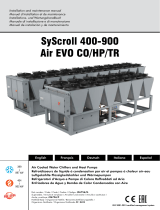
DESCRIPTION
Controls and regulation
Removable front air intake
panel
Access panel to connections
(refrigerant, water, power
supply)
Air discharge
operings
Access panel to ventilator
motor unit and the electric
heating or hot water battery
(accessory)
2. Pipe links to main unit (air cooled)
Cooling water supply (water cooled)
² Waste water supply = male 50x60 - 2"
² Recycled water supply =nut F 26x34 - 1
1. Pipe links to main unit (air cooled)
Cooling water supply (water cooled)
² Waste water outlet = male 50x60 - 2"
² Recycled water outlet = nut F 26x34 - 1"
3. Condensate water evacuation – souple tube Ø
26x32
4. Electric connection - with "Faults report"
5. Electric connection - with "Remote control"
6. General electric supply
7. Electric connections to UC (air cooled)
8. Incorporated hot water battery inlet and outlet (M. Ø
40x49)
9. Safety evacuation at the base of unit
10. Packaging fixing holes (2 front - 2 rear). To be stopped up with the unit fixing bolts on its pallet
11. Hole Ø 315 for possible connection of a new air inlet duct (to be carrier by the installer)
12. Rings situated at the 4 corners of the cabinet for vertical lifting (bar system).
A
A
8
10
9
11
12
12
1
5
7
6
2
3
4
X 4650
1
5
7
6
2
3
4
X 6450
8

INSTALLATION
The unit is not designed to withstand weights or stresses from adjacent equipment, pipe work or
constructions. Any foreign weight or stress on the unit structure could lead to a malfunction or a
collapse with dangerous consequences for personnel and property. In such an event, the warranty
shall be null and void.
CLEARANCE
1. on the connection side
2. for total rear air intake
3. for front air discharge with plenum accessory
4. for direct vertical air discharge
RESPECT MINIMUM CLEARANCES SPECIFIED AROUND THE UNIT.
INSTALLATION OF THE INDOOR UNIT
The unit base shall be arranged as indicated in the manual. There could be a risk of personal injury
or damage to property in the event of the unit being incorrectly supported.
The unit must be installed on a firm level foundation, of adequate strength to support its full operating weight.
1. It must be high enough to permit good drainage of condensates with siphon
2. The unit must be pitched slightly towards condensate drain outlet to provide positive drainage of
condensates.
3. Keep duct connections to a minimum to reduce duct losses.
4. When locating unit give consideration to, and locate unit as remote as possible minimise noise.
5. All electrical and ductwork connections to the unit must be made via flexible connections to prevent
transmission of vibration.
6. In addition to the service clearances noted on the dimension sheet it is essential that provision is
made for adequate and safe service access.
UNIT LOCATION
1200
mm
650m
m
650m
m
650mm
900mm
1
1
2
4
3
9

Before final installation of the unit mount the accessories (heater, rear or side air intake, plenum etc...). See the
specific document supplied with each accessory.
Remove the upper front panel, air intake panel and lower front
panel according to the instructions.
² REMOVAL OF UPPER FRONT PANEL A
(Access to the fan and the electrical heating or hot
water battery (accessory))
Unscrew the two screws, pull out and up.
² REMOVAL OF THE FRONT AIR INTAKE B
Turn the two fasteners by a quarter turn, pull out and
up.
² REMOVAL OF LOWER FRONT PANEL C
(Access to refrigerant, hydraulic and electrical
connections)
Unscrew the two screws, pull out and up.
AIR DISCHARGE AND INTAKE
1. Direct air intake through the removable front panel A and the filter D (factory mounted).
2. Total rear air intake with duct:
Duct E to be mounted on the rear of the unit connection elements (remove the panel J).
3. Direct air discharge through plenum F with ajustable grilles (accessory) which are mounted on the
unit.
4. Air dischage through ducts:
Connection elements for air discharge ducts G (accessory) to be mounted on the top of the unit.
5. Possibility of partial fresh air intake, on side or rear with the accessory air intake duct H.
A
D
J
E
F
G
H
D
K
M
L
1
2
Access to the filters
1. Take off the air intake panels.
2. The filters D are maintained :
² in the fixed supports K, situated in the lower part of the evaparator M
² by the detachable supports L situated in the upper part the evaporator
3. To take them off :
² 1 Lift and
² 2 Pull.
C
A
B
B
1
2
4
6
4
2
1
3
3
3
3
B
3
3
C
B
4
3
3
B
4
3
3
5
5
6
10

ATTACHMENT TO THE GROUND
INSTALLATION OF THE OUTDOOR UNIT
Place the AIR COOLED condenser outdoors in a location not
accessible to the public and without air pollution (smoke, acid, etc...).
CLEARANCES.
Respect the minimum dimension indicated for correct operation and to
avoid air recycling, even partially between air intake and air discharge.
INSTALLATION.
Install and attach the AIR COOLED condenser on a masonry surface (concrete slab).
X
Access panel
electrical section
4 oblong holes 9x16 mm
229
229
11
900
1085
11
104104
4 oblong holes 9x16 mm
101
121,5
635
1340
102
121,5
104104
7474
101
102
121,5
635
935
121,5
151
230
900
760
7474
4 holes Ø10 mm 4 holes Ø10 mm
74 and 104 with the feet X used for fixing the unit to its pallet
or by the holes drilled in the bosses situated under the base of the unit. They can be reached after dismantling the
side panels.
11

A1
B1
A2
B2
A
B
PIPES TO BE MADE ON SITE
REFRIGERANT LINES
² Supplied precharged in factory:
MAXIMUM LENGTH 25M.
² Realized on the site by the installer:
MAXIMUM LENGTH 45M.
REFRIGERANT
linking pipes up to 45m:
² GAS line:
gas precharge
² LIQUID line (above to 2m):
4650 110g/m 6450 183g/m
For refrigerant lines with a length between 25 and 45m (to be mounted on the site) the diameters, the refrigerant
charge and the installation safety measures must be determined professionally.
Minimum slope
1cm/m downwards
Condenseur higher than the
indoor unit
Condenseur at the same level as the
indoor unit
Condenseur lower than the
indoor unit
L
L
H
L
H
L. max = 45m H. max = 20m
(L+H) max = 45m
H. max = 9m
(L+H) max = 45m
REFRIGERANT CONNECTIONS (AIR COOLED UNIT)
The outdoor unit are factory charged and equipped with refrigerant connections. Follow
the connection instructions for the valves with non-removable membranes.
The couplings are situated behind the lower front panel of the unit,
to the rear.
² Valve A: GAS line
4650 Ø 5/8" 6450 Ø 3/4
² Valve B: LIQUID line
4650 Ø 1/2" 6450 Ø 5/8"
Valve LIQUID line
Cable passage
Valve GAS line
BACK SIGHT
Discharge
Liquid
"Discharge" line
"Liquid" line
Discharge
Liquid
OUTDOOR UNIT
INDOOR UNIT
12

This operation should be performed expertly by qualified
professionals (refrigeration engineer) (brazing, vacuum,
charge, etc ...).
The bending radius of the pipes should be equal to or more than 3,5 times de outside
diameter of the pipe.
REFRIGERATION PIPE BENDING
Do not bend the pipes consecutively more than three times and do not make more than
12 bends over the complete length of the link.
Unroll the pipes carefully, in the opposite direction to the
spirals, to avoid bending them.
TIGHTENING TORQUE FOR REFRIGERANT VALVES
FOLLOW THE CONNECTION INSTRUCTIONS FOR THE VALVES WITH NON-REMOVABLE
MEMBRANES
² Line up the 2 half couplings.
² Remove the protective plugs on each coupling.
² Check if the valves are greased on the inside; if not, lubricate them slightly with oil fit refrigeration
use.
² Give a few clockwise turns by hand, to make sure threading is engaged properly.
² Continue screwing clockwise with a wrench, while holding the rear part ( tube side ) with another
wrench placed counter-clockwise, until it is firmly tighten . Just then, resume locking with an additional
1/4 turn of the wrench.
² The reason for this last step is to crimp the internal metal gasket.
NOTE
² Prior to final butt-screwing, a slight freon leak may be noticed which should stop quickly.
² Proceed to leak tests.
² LIQUID:
(small valve) 15Nm
² SUCTION:
(large valve) 55Nm
1 Newton-meter = 0,1 meter-kilo
FOR SAFETY’S SAKE NEVER DISCONNECT
THESE COUPLINGS WHILE CIRCUIT IS UNDER REFRIGERANT PRESSURE
13

HYDRAULIC CONNECTIONS
The cooling water inlet and outlet (water cooled models) is made by hoses situated in the lower part of the unit
with female union nuts on their ends.
Passage provided on the right or left side.
Condensate drain: the hose (26 x 32) coiled in the lower part of the unit must be brought out through the hole
3 page 8.
SAFETY DRAIN.
The sealed bottom of the indoor unit which collects condensate or abnormal overflow is equipped with a right or
left lateral outlet pipe 22mm outer diameter.
The condensate drain pipe must have a minimum slope of 2,5 cm/m in the flow direction.
In case of connection to the sewer it is necessary to provide a trap on the drain pipe.
Thermical insulation (6 mm mini) must be provided when necessary (risk of freezing or condensation).
ELECTRICAL CONNECTIONS
The electrical box is situated behind the lower front pane.
General supply through the power terminals situated on the left in the electric box, behind the plastic protection
cover.
CAUTION
In the case of a casing heater it must be started according to the compressor is located: 2 hours before starting of
the unit for a temperature of 10°C and 4 hours before starting for a temperature of 0°C.
IMPORTANT
Observe the correct order for the electrical connections, including the mains supply (phase, neutral,
earth, etc...), in accordance with the markings on the terminal strip.
The outdoor units are supplied wired for a three-phase 400VAC 3-phase + Earth power supply voltage.
Power supply
3 ~ 400V + Earth
(without neutral)
The shunt SHA (1) must be removed.
Power supply
400VAC 3-phase + Earth
(with neutral)
Power supply
230VAC 3-phase + Earth
Transformer (not supplied)
-For power supply 400VAC - 3-phase + Earth, without neutral
TRANSFORMER
Nominal input power single phase
transformer 400V - 230V
250 VA
SG : GENERAL SELECTOR MANDATORY
FF0 - FF1 - FT1 : FUSE TYPE aM
T1 : TRASFORMER 400/230 V
to be supplied by installer (comply with local regulations)
3 ~ 400V - 50Hz +
1 ~ 230V - 50Hz +
3N ~ 400V - 50Hz +
3 ~ 230 V - 50 Hz +
14

INTERCONNECTIONS
4650 6450
COOLING + FAN
Nominal current A 1 1
Maximum current A 2 2
Starting current A 4 4
Cable size mm² 1 1
INTERCONNECTIONS WITH REMOTE CONTROL
NOTE : Motors 74 and 104 are coupled of single phase 400/230 V.coupling.
² They are supplied ex-factory coupled for 400 V between two phases.
² To are to be coupled on site at the power supply voltage of the cabinet, that is single phase 230 V
for a three phase 230 V units.
6450
2
3
4
79
2
3
4
5
8
79
2
3
4
79
2
3
4
5
8
79
104
4650
2
3
4
5
2
3
4
5
2
3
4
5
2
3
4
5
74
15

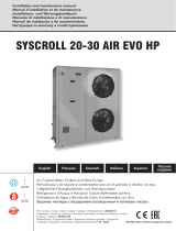
CONTROL PANEL
Manual hot/cold operation with basic thermostat
Automatic cooling/heating operation with basic thermostat
Automatic operation with a four-stage thermostat
COOLING (F1 + F2)
(mandatory position)
HEATING (C1 + C2) (3)
(mandatory position)
COOLING/HEATING
(mandatory position)
COOLING/HEATING
(mandatory position)
IMPORTANT :
Never press simultaneously
on the position codem.
Automatic regulation is on one cold stage (F2)
and one hot stage (C2) (3).
Note : When the unit features an electrical heater, to optimize equipment performance, it is preferable to use the
four-stage thermostat or any othermeans of regulation available to the user.
2 COOLING stages (F1 + F2
2 HEATING stages (C1 + C2) (3)
(1) Automatic basic thermostat
(2) Equipment with automatic cooling/heating thermostat - four stages and electrical heater (accessories to
order)
(3) The entire electrical power for this stage is reached after a four minute time delay.
1. Ventilation On/Off switch
O Off
1 On (with control light)
2. "Cooling" selection switch
O Off
1 Automatic operation only (1) - F1 + F2
Automatic cooling/heating operation (2)
3. "Heating" selection switch
O Off
1 Automatic heating alone (1) C1 + C2
Automatic heating (2) /cooling
4. Built-in thermostat
– switch for cooling or heating control
5. Fault ventilation
6. Fault compressor 1
7. Fault compressor 2
Symboles
Important :
Switch in fan ON
POSITION
Pressed
5
2
1
I
I
I
O
O
O
3 4
6 7
I
O
I
I
O
O
I
I
I
O
O
O
I
I
I
O
O
O
I
I
I
O
O
O
I
I
I
O
O
O
HP Pressure switch compressor
thermal control
16

And that the following paragraphs of the harmonised standards have been applied.
Et que les paragraphes suivants les normes harmonisées ont été appliqués.
Und dass die folgenden Paragraphen der vereinheitlichten Normen Angewandt wurden.
E che sono stati applicati i seguenti paragraphi delle norme armonnizzate.
Y que se han aplicado los siguientes apartados de las normas armonizadas.
X 4650ARV / X 6450 ARV
UC 74 / UC 1044
X 4650 AO4
MACHINERY DIRECTIVE 2006 / 42 / EEC
LOW VOLTAGE DIRECTIVE (DBT) 2006 / 95 / EEC
ELECTROMAGNETIC COMPATIBILITY DIRECTIVE 2004 / 108 / EEC
PRESSURISE EQUIPMENT DIRECTIVE (DESP) 97 / 23 / EEC
SUB-MODULE A CATEGORY I: UC 74 / UC 104
SUB-MODULE A1 CATEGORY II: X 4650 ARV / X 4650 AO
X 6450 ARV
NOTIFIED BODY: TÜV RHEINLAND – 62 BIS, AVENUE HENRI GINOUX– 92120 MONTROUGE - FRANCE
THE PRODUCTS ARE PROVIDED WITH CE 0035 MARKING OF CONFORMITY
DIRECTIVE MACHINES 2006 / 42 / C.E.E.
DIRECTIVE BASSE TENSION (DBT) 2006 / 95 / C.E.E.
DIRECTIVE COMPATIBILITE ELECTROMAGNETIQUE 2004 / 108 / C.E.E
DIRECTIVE DES EQUIPEMENTS SOUS PRESSION (DESP) 97 / 23 C.E.E.
SOUS-MODULE A CATEGORIE I : UC 74 / UC 104
SOUS-MODULE A1 CATEGORIE II : X 4650 ARV / X 4650 AO
X 6450 ARV
AVEC SURVEILLANCE PAR LE TUV RHEINLAND 62 BIS, AVENUE HENRI GINOUX– 92120 MONTROUGE - FRANCE
LES PRODUITS SONT FOURNIS AVEC LE MARQUAGE DE CONFORMITE CE 0035
RICHTLINIE MASCHINEN 2006 / 42 / EG
RICHTLINIE NIERDERSPANNUNG (DBT) 2006 / 95 / EG
RICHTLINIE ELEKTROMAGNETISHE VERTRÄGLICHKEIT 2004 / 108 / EG
RICHTLINIE FÜR AUSRÜSTUNGEN UNTER DRUCK (DESP) 97 / 23 / EG
UNTER MODUL A, KATEGORIE I : UC 74 / UC 104
UNTER MODUL A1, KATEGORIE II : X 4650 ARV / X 4650 AO
X 6450 ARV
MIT KONTROLLE DURCH DEN TUV RHEINLAND 62 BIS, AVENUE HENRI GINOUX– 92120 MONTROUGE - FRANCE
DIE PRODUKTE WERDEN MIT DER MARKIERUNG CONFORMITE CE 0035 GELIEFERT.
DIRETTIVA MACHINE 2006 / 42 / CEE
DIRETTIVA BASSA TENSIONE (DBT) 2006 / 95 / CEE
DIRETTIVA COMPATIBILITA ELETTROMAGNATICA 2004 / 108 / CEE
DIRETTIVA DEGLI IMPIANTI SOTTO PRESSIONE (DESP) 97 / 23 / CEE
SOTTOMODULO A, CATEGORIA I : UC 74 / UC 104
SOTTOMODULO A1, CATEGORIA II : X 4650 ARV / X 4650 AO
X 6450 ARV
CON SUPERVISION POR EL TUV RHEINLAND 62 BIS, AVENUE HENRI GINOUX– 92120 MONTROUGE - FRANCE
I PRODOTTI SONO FORNITI CON LA MARCATURA DI CONFORMITE CE 0035.
DIRECTIVA MAQUIAS 2006 / 42 / CEE
DIRECTIVA BAJA TENSION (DBT) 2006 / 95 / CEE
DIRECTIVA COMPATIBILIDAD ELECTROMAGNETICA 2004 / 108 / CEE
DIRECTIVA DE LOS EQUIPOS A PRESION (DESP) 97 / 23 / CEE
BAJA MODULO A, CATEGORIA I : UC 74 / UC 104
BAJA MODULO A1, CATEGORIA II : X 4650 ARV / X 4650 AO
X 6450 ARV
CON SORVEGLIANZA DAL TUV RHEINLAND 62 BIS, AVENUE HENRI GINOUX– 92120 MONTROUGE - FRANCE
LOS PRODUCTOS SE PROPORCIONAN CON EL MARCADO DE CONFOR CE 0035.
Déclaration CE de conformité
Nous déclarons sous notre responsabilité que les produits désignés dans la présente notice sont conformes aux dispositions des directives CEE énoncées
ci- après et aux législations nationales les transposant.
EC Compliance declaration
Under our own responsibility, we declare that the product designated in this manual comply with the provisions of the EEC directives listed hereafter
and with the national legislation into which these directives have been transposed.
EG-Konformitätserklärung
Wir erklarën in eigener Verantwortung, das die in der vorliegenden Beschreibung angegebenen Produkte den Bestimungen der nachstehend erwähn-
ten EG-Richtlinien und den nationalen Gesetzesvorschriffen entsprechen, in denen diese Richtinien umgesetz sind.
Dichiarazione CE di conformità
Dichiariamo, assurmendone la responsasabilità, che i prodotti descritti nel presente manuale sono conformi alle disposizioni delle direttive CEE di cui
sott e alle lagislazionni nazionali che li recepiscono
Declaramos, bajo nuestra responsabilidad, que los productos designados en este manual son conformes a las disposiciones de las directivas CEE enu-
nuciadas a continuacion, asi como a las legislaciones nacionales que las contemplan.
Declaración CE de conformidad
EN 378 EN 61 000-6-1 EN 61 000-6-3
EN 60 335-1 EN 60 335-2-40 EN 61 000-3-11
EN 61 000-3-12
A Tillières sur Avre
27570 - FRANCE
Le: 25/09/2013
Sébastien Blard
Quality Manager
AIRWELL Industrie France

As part of our ongoing product improvement programme, our products
are subject to change without prior notice. Non contractual photos.
Dans un souci d’amélioration constante, nos produits peuvent être
modifiés sans préavis. Photos non contractuelles.
In dem Bemühen um ständige Verbesserung können unsere Erzeugnisse
ohne vorherige Ankündigung geändert werden. Fotos nicht vertraglich
bindend.
A causa della politica di continua miglioria posta in atto dal costruttore,
questi prodotti sono soggetti a modifiche senza alcun obbligo di preavviso.
Le foto pubblicate non danno luogo ad alcun vincolo contrattuale.
Con objeto de mejorar constantemente, nuestros productos pueden
ser modificados sin previo aviso. Fotos no contractuales.
AIRWELL
IndustrIe France
Route de Verneuil
27570 Tillières-sur-Avre
FRANCE
& : +33 (0)2 32 60 61 00
6 : +33 (0)2 32 32 55 13
/