Page is loading ...

AVANTI FALL PROTECTION SYSTEM
User’s, Installation and Maintenance Manual
Runner 2000/2002 & Eagle
DS
Runner
®
Original instructions
MASTER 47840008 EN_CORREGIDO.indd 1 25/10/17 12:01

2
User‘s Manual and Installation Instructions
Only trained people may use this fall protection system.
This manual must be available to staff at all times during installation, maintenance and operation. Additional copies are available from the manufacturer
upon request.
This manual, including, but not limited to, measurements, procedures, components, descriptions, instructions, recommendations and requirements, is
subject to change without prior notice. Please check Avanti website/manuals for the latest revisions of the manuals.
Any additional cost related to or arising from any changes in the manuals does not entitle Customer to any form of compensation or other legal remedies.
Date of publication:
11
th
Edition: January 2017
Revision 3: 10/10/2017
Manufacturer:
Avanti Wind Systems A/S
Rønnevangs Allé 6
3400 Hillerød
Denmark
P: (+45) 4824 9024
F: (+45) 4824 9124
E: info@avanti-online.com
I: www.avanti-online.com
AVANTI Fall Protection System
Sales & Service:
Australia Avanti Wind Systems PTY LTD P: +61 (0) 3 9585 1852
China Avanti Wind Systems P: +86 21 5785 8811
Denmark Avanti Wind Systems A/S P: +45 4824 9024
Germany Avanti Wind Systems GmbH P: +49 (0) 41 21-7 88 85 – 0
Spain Avanti Wind Systems SL P: +34 976 149 524
UK Avanti Wind Systems Limited P: +44 0 1706 356 442
USA Avanti Wind Systems,Inc P: +1 (262) 641-9101
India Avanti Wind Systems India (P) Ltd P: +91 95 00 173 492
Brazil Avanti Brasil Sistema Eólicos LTDA P: +55 85 9 9955-0090
Manufactured Under Process Patent NO.8,499,896.
® Registered in Europe
MASTER 47840008 EN_CORREGIDO.indd 2 25/10/17 12:01

3
1. Limited Warranty..................................... 6
1.1 Terms and definitions .............................. 6
2. Cautions ........................................... 7
3. Description of equipment .............................. 8
3.1 Purpose ......................................... 8
3.2 Function ........................................ 8
3.3 Component overview .............................. 8
3.4 Marking ......................................... 9
4. Installation.......................................... 9
4.1 Installation requirements ........................... 9
4.2 Installation of the rail system on the ladder ............. 10
4.2.1 Safety rail at the tower flange connections......... 11
5. Inspection before the first use .......................... 12
6. Daily inspection ..................................... 12
7. Instructions for use ................................... 12
7.1 Instructions for use of Runner 2000/2002 .............. 12
7.1.1 Attaching the Runner 2000/2002 to the safety rail .... 12
7.1.2 Releasing the Runner 2000/2002 from the safety rail . 13
7.2 Instructions for use of Eagle
DS
Runner ................. 13
7.2.1 Attaching the Eagle
DS
Runner to the safety rail ...... 13
7.2.2 Releasing the Eagle
DS
Runner from the safety rail .... 14
8. Maintenance ........................................ 15
8.1 Cautions ........................................ 15
8.2 Storage ......................................... 15
8.3 Annual inspection ................................. 15
8.4 Inspection procedure .............................. 15
8.4.1 Ladder rungs................................. 15
8.4.2 Ladder stiles ................................. 16
8.4.3 Flange connection kits ......................... 16
8.4.4 Ladder ends ................................. 16
8.4.5 Safety rail ................................... 16
8.4.6 Fish-joints ................................... 16
8.5 Ordering spare parts .............................. 16
9. Appendix A: Annual inspection checklist ............... 17
10. Appendix B: Daily inspection checklist of Runner 2000/2002 19
11. Appendix C: Daily inspection checklist of Eagle
DS
Runner .. 20
12. Appendix D: Inspection log sheet ..................... 21
Index
MASTER 47840008 EN_CORREGIDO.indd 3 25/10/17 12:01

4
CE certificate of AVANTI Fall Protection System with Runner 2000/2002:
MASTER 47840008 EN_CORREGIDO.indd 4 25/10/17 12:01

5
CE certificate of AVANTI Fall Protection System with Eagle
DS
Runner:
MASTER 47840008 EN_CORREGIDO.indd 5 25/10/17 12:01

6
1.1 Terms and definitions
Terms Definitions
Certified technician
Person who has gone through the relevant training associated with the scheduled task from Avanti
or from a certified trainer and is in possession of a valid (non expired) certificate for the task.
User
Person who has gone through the relevant training associated with the Avanti service lift
use and daily inspection and is in possession of a valid (non expired) certificate for the task.
Avanti Wind Systems A/S warrants that commencing from the
date of shipment to the Customer, and continuing for a period of
the longer of 365 days thereafter, or the period set forth in the
standard Avanti warranty, the Fall Protection System (“Product”)
described in this Manual will be free from defects in material and
workmanship under normal use and service when installed and
operated in accordance with the provisions of this Manual.
This warranty is made only to the original user of the Product.
The sole and exclusive remedy and the entire liability of Avanti
under this limited warranty, shall be, at the option of Avanti, a re-
placement of the Product (including incidental and freight charges
paid by the Customer) with a similar new or reconditioned Prod-
uct of equivalent value, or a refund of the purchase price if the
Product is returned to Avanti, freight and insurance prepaid. The
obligations of Avanti are expressly conditioned upon return of the
Product in strict accordance with the return procedures of Avanti.
This warranty does not apply if the Product (i) has been altered
without the authorization of Avanti or its authorized representa-
tive; (ii) has not been installed, operated, repaired, or maintained
in accordance with this Manual or other instructions from Avanti;
(iii) has been subjected to abuse, neglect, casualty, or negli-
gence; (iv) has been furnished by Avanti to Customer without
charge; or (v) has been sold on an “AS-IS” basis.
Except as specically set forth in this Limited Warranty, ALL
EXPRESS OR IMPLIED CONDITIONS, REPRESENTATIONS
AND WARRANTIES, INCLUDING, BUT NOT LIMITED TO, ANY
IMPLIED WARRANTY OR CONDITION OF MERCHANTABILITY,
FITNESS FOR A PARTICULAR PURPOSE, NON-INFRINGE-
MENT, SATISFACTORY QUALITY, COURSE OF DEALING,
LAW, USAGE OR TRADE PRACTICE ARE HERBY EXCLUDED
TO THE MAXIMUM EXTENT PERMITTED BY APPLICABLE
LAW AND ARE EXPRESSLY DISCLAIMED BY AVANTI. IF,
PURSUANT TO ANY APPLICABLE LAW, TO THE EXTENT AN
IMPLIED WARRANTY CANNOT BE EXCLUDED AS PROVIDED
IN THIS LIMITED WARRANTY, ANY IMPLIED WARRANTY IS
LIMITED IN TIME TO THE SAME DURATION AS THE EXPRESS
WARRANTY PERIOD SET FORTH ABOVE. BECAUSE SOME
STATES DO NOT PERMIT LIMITATIONS ON THE DURA-
TION OF IMPLIED WARRANTIES, THIS MAY NOT APPLY TO
A GIVEN CUSTOMER. THIS LIMITED WARRANTY GIVES
CUSTOMER SPECIFIC LEGAL RIGHTS, AND CUSTOMER MAY
HAVE OTHER LEGAL RIGHTS UNDER APPLICABLE LAWS.
This disclaimer shall apply even if the express warranty fails of its
essential purpose.
In any cases of dispute the English original shall be taken as
authoritative.
1 Limited Warranty
MASTER 47840008 EN_CORREGIDO.indd 6 25/10/17 12:01

7
2 Caution
a) The AVANTI Fall Protection System (hereafter named as FPS) shall
only be operated by users trained in daily inspection, use and work at
heights.
b) A user is trained on the correct usage of the AVANTI Fall Protection
System (FPS) and is familiar with the following standards: EN 353-1, EN
363 and EN 365.
c) A certified technician has successfully participated in the AVANTI Fall
Protection course.
d) A certified technician is qualified personnel authorised by AVANTI to
perform installation, inspection and maintenance tasks.
e) The installation, maintenance and testing of the FPS may only be per-
formed by a certified technician.
f) Users are obliged to read and understand this User’s Manual.
g) A copy of the User’s Manual shall be handed out to the FPS users and
shall be available for reference.
h) If more than one person is trusted with one of the above tasks, the
employer shall appoint a supervisor in charge of operation.
i) If the FPS is re-sold outside the original country of destination, the
reseller shall provide instructions for use, for maintenance, for periodic
examination and for repair in the language of the country in which the
product is to be used.
j) The ladder system shall be capable of supporting 15 kN. This shall be
verified by calculations made by a qualified engineer or by static load
testing.
k) The FPS shall not be used by persons under the influence of alcohol or
drugs that may jeopardise the safety.
l) The FPS shall not be used by persons affected by vertigo, heart or lung
disorders, or other known weakening diseases/conditions.
m) The FPS users shall be aware of the dangers of suspension trauma
should a fall occur.
n) Owner shall ensure that a rescue plan is in place and that the users are
familiar with it. The rescue plan shall deal with any emergencies that
could arise during ascent and descent with the FPS.
o) No warranty is provided against damage resulting from reconstruction
or modification of equipment or use of non-original parts which are not
approved by the manufacturer.
p) The runner shall be handed out and treated as a personal protection
equipment.
q) The weight of the user, excluding tools and equipment, shall not be less
than 40 kg. The weight of the user, including tools and equipment, shall
not exceed 136 kg.
r) The maximum number of multiple users in the ladder system is 3.
The fall arrester must be attached to no more than one personal fall-
arrest system.
s) In the first two meters above the ground level, the user may not be
protected against hitting the ground if a fall occurs.. Other additional
safeties shall be provided for this purpose.
t) Prior to the first use of the FPS, a certified technician must inspect and
approve the complete FPS.
u) If oil, grease or the like has leaked onto the safety rail – wipe it off.
v) If oil, grease, chemicals or the like has leaked onto the shock absorber
or in any kind been in contact with the webbing, have an AVANTI FPS
certified technician replace the shock absorber.
w) The shock absorber has a limited life. Its date of expiration is printed
on the shock absorber label.
x) The operation temperature of the FPS is -30º / +60º Celsius.
y) The FPS shall only be used in connection with a full body harness that
is approved according to EN 361.
z) The FPS has been tested and approved according to EN 353-1:2014.
aa) The type-examination of the FPS has been performed by: FORCE
Certification A/S, EC Notified Body 0200, Park Allé 345, DK-2605
Brøndby.
ab) The production control of the FPS is performed by the same notified
body.
ac) These instructions shall be kept together with the permanent installed
parts of the FPS (i.e. the rail system).
Owner shall verify the need for FPS inspections with the
local authority and comply with the standards specied.
ad) When working at heights, the user shall minimise both the risk of
potential falls and the potential fall distance.
ae) In order to avoid collisions with the ground or obstacles should a fall
occur, the user shall verify the free space required beneath his/her
actual position taking into account sharp edges, electrical conductivity
and pendulum falls.
af) The safety of the users depends upon the continued efficiency and
durability of the FPS. Thus, regular periodic inspections shall be car-
ried out, minimum every 12 months.
ag) All the FPS parts have been especially developed and tested for
AVANTI´s FPS. Thus, they shall not be used as part of other Fall Pro-
tection Systems.
MASTER 47840008 EN_CORREGIDO.indd 7 25/10/17 12:01

8
3.1 Purpose
a) The FPS is intended for use during ascent and descent on stationary
ladders installed in towers, pylons, well shafts, or alike.
b) The FPS is a safety system that arrests a fall of the user during climbing.
c) The runner travels along a safety rail.
d) The safety rail is designed for permanent installation at one place.
e) The safety rail can be installed on ladders of different shapes and brands
as long as an approval is issued before by AVANTI.
f) The FPS is not designed for securing horizontally or for securing equip-
ment. The FPS shall never be used for work positioning or for securing
equipment. If work positioning at the ladder is required, a separate
dedicated and approved work positioning equipment shall be used.
g) The FPS may not be used outside its limitations, or for any purpose other
than that for which it is intended.
3.2 Function
a) The user attaches the runner to the designated D-ring marked “A” in the
front of his full body harness by means of the integrated shock absorber
and the carabiner. (In case of two D-rings marked “A” in the front of full
body harness, both rings act together like an only point of attachment,
do not individually).
3 Description of equipment
ah) The combination of FPS parts in anyway other than the intended
will jeopardize safety. Thus, the FPS parts shall not be combined in
anyway other than the intended.
ai) The FPS shall never be adapted, extended, or changed in any way.
b) Before starting to climb, the user clicks the runner on the safety rail and
checks its locking.
c) When climbing, the runner glides along the safety rail. In case that the
user experiences a fall, the runner will lock on the safety rail and arrest
the person falling.
3.3 Component overview
a) The FPS comprises the rail system and the runner system.
b) The safety rail system comprises: the safety rail sections, the rung
fittings, the top and bottom rail-stops, the fish-joints, hammerhead
screws and self-locking nuts.
c) The runner comprises: the runner itself, the shock absorber, and the
carabiner.
d) There are two runner models covered in this manual: Runner
2000/2002 and Eagle
DS
Runner. Both models fit the AVANTI rail.
Rail
Rung fitting
Runner
Shock
Absorber
Carabiner
Runner 2000/2002
Eagle
DS
Runner
MASTER 47840008 EN_CORREGIDO.indd 8 25/10/17 12:01

9
STOP
Denmark
R
ønnevangs Allé 6
DK-3400 Hillerød
AIP ApS
47799067
Eagle DS
Serial number plate
Format:
A4
ISO 2768-mK
1 / 1
04
Sheet no.
Title:Tolerances:
Scale:
2:1
DateRev. Appr. Release Change Description
Treatment:
Proj.
Material:
Edge:
Dwg No.: Rev.Weight:
Mat. format.:
THIS DOCUMENT AND ITS CONTENTS ARE PROPRIETARY TO AIP ApS AND PROTECTED BY COPYRIGHT. THEY ARE CONFIDENTIAL AND MAY CONTAIN LEGALLY PRIVILEGED INFORMATION.
COPYING, SUBMITTING TO THIRD PARTIES OR USE IN ANY FORM AND FOR ANY PURPOSE OTHER THAN THAT ORIGINALLY INTENDED IS PROHIBITED WITHOUT THE EXPRESS PREVIOUS WRITTEN CONSENT OF AIP ApS.
0,003 kg
AW5754 H111
No treatment
Updated to PDM format and CE standards updated.
04
DeburredSheet 0.8 mm
Eagle DS
EN 353-1:2014
Type: Rail Mount Size: AVANTI Fall Protection Rail Only. Read and follow
all instructions before use. Inspect device prior to each use.
User weight:
Serial No.:
Production date:
www.avanti-online.com
P: (+45) 4824 9024
UP
40 - 136 kg
Set of QC measuring points:
C
A
B
A
B
C
0200
Stamp serial no.
Stamp production date
Back side
Serial No.
UP
Note: (Applies only to back side)
1. Black text including serial No.
2. Text height 5mm
3. Serial No. same as front side
UP
UP
9.5
70
64
18
9
2
.
5
(
2
x)
R2.5
Denmark
R
ønnevangs Allé 6
DK-3400 Hillerød
AIP ApS
47799044
Avanti Fall Arrester
Shock absorber label
Format:
A4
ISO 2768-mK
1 / 1
03
Sheet no.
Title:Tolerances:
Scale:
1:1
DateRev. Appr. Release Change Description
Treatment:
Proj.
Material:
Edge:
Dwg No.: Rev.Weight:
Mat. format.:
THIS DOCUMENT AND ITS CONTENTS ARE PROPRIETARY TO AIP ApS AND PROTECTED BY COPYRIGHT. THEY ARE CONFIDENTIAL AND MAY CONTAIN LEGALLY PRIVILEGED INFORMATION.
COPYING, SUBMITTING TO THIRD PARTIES OR USE IN ANY FORM AND FOR ANY PURPOSE OTHER THAN THAT ORIGINALLY INTENDED IS PROHIBITED WITHOUT THE EXPRESS PREVIOUS WRITTEN CONSENT OF AIP ApS.
0,002 kg
Paper
See Treatment Note
Updated standards and updated to PDM format
03
Not applicable
TREATMENT NOTE:
Plastic Paper with adhesive face.Adhesive 3M on text side of the label
0.8
Thickness maximum
Black text
Adhesive on text side
C
A B C
Set of QC measuring points:
03
Denmark
R
ønnevangs Allé 6
DK-3400 Hillerød
AIP ApS
47799015
Fall arrester type 2000/2002
Serial number plate
Format:
A4
ISO 2768-mK
1 / 1
09
Sheet no.
Title:Tolerances:
Scale:
2:1
DateRev. Appr. Release
Change Description
Treatment:
Proj.
Material:
Edge:
Dwg No.: Rev.Weight:
Mat. format.:
THIS DOCUMENT AND ITS CONTENTS ARE PROPRIETARY TO AIP ApS AND PROTECTED BY COPYRIGHT. THEY ARE CONFIDENTIAL AND MAY CONTAIN LEGALLY PRIVILEGED INFORMATION.
COPYING, SUBMITTING TO THIRD PARTIES OR USE IN ANY FORM AND FOR ANY PURPOSE OTHER THAN THAT ORIGINALLY INTENDED IS PROHIBITED WITHOUT THE EXPRESS PREVIOUS WRITTEN CONSENT OF AIP ApS.
0,003 kg
AW5754 H111
No treatment
Updated to PDM format. US/CAN standards eliminated and CE standards updated.
09
DeburredSheet 0.8mm
Runner 2000/2002
EN 353-1:2014
Type: Rail Mount Size: AVANTI Fall Protection Rail Only. Read and follow
all instructions before use. Inspect device prior to each use.
User weight:
Serial No.:
Production date:
www.avanti-online.com
P: (+45) 4824 9024
UP
40 - 136 kg
0.8
70
64
18
9
R2.5
2
.
5
(
2x
)
Set of QC measuring points:
C
A
B
A
B
C
3
0200
Stamp serial no.
Stamp production date
Back side
Serial No.
Black text
UP
Note: (Applies only to back side)
1. Black text including serial No.
2. Text height 5mm
3. Serial No. same as front side
UP
UP
9.5
09
4 Installation
4.1 Installation requirements
A certi ed technician shall be in charge of the FPS installation.
The certi ed technician shall take full responsibility for the instal-
lation and shall guarantee that it is done in accordance to these
instructions.
a) The FPS shall only be installed with original system parts.
b) All FPS elements shall be checked on site, even if the ladders are sup-
plied with the rails already fi tted.
c) The vibrations and torsional stress are absorbed by the ladder joints, not
by the safety rail.
d) Ensure that the ladder intended for mounting the FPS complies with the
requirements of EN 131 and EN ISO 14122. The internal rung width shall
be minimum 340mm (all AVANTI ladders meet this requirement).
e) The ladders with rung geometries different to AVANTI‘s may call for
special rung fi ttings. Prior to installation, these ladders shall be calculated,
tested and approved by AVANTI.
f) Before installing the rail system, ensure that all parts are present. Refer to
the parts list supplied with the FPS.
g) The ladders shall be installed vertically with a maximum inclination
of -5º / +15º.
h) The parts of the safety rail system to be installed are shown below.
Runner rating plate
Upward direction when mounted onto rail
Read instructions before use
Runner production no.
EEC-notifi ed body no.
AVANTI product name (Runner System 2000/2002 or Eagle
DS
)
Standard no.
Read instructions before use
Serial No.:
0200
0200
Runner production no.
EEC-notifi ed body no.
AVANTI product name (Runner System 2000/2002 or Eagle
Standard no.
Serial No.:
Runner production no.
EEC-notifi ed body no.
AVANTI product name (Runner System 2000/2002 or Eagle
Standard no.
Runner production no.
EEC-notifi ed body no.
Serial No.:
Serial No.:
Serial No.:
Serial No.:
EEC-notifi ed body no.
AVANTI product name (Runner System 2000/2002 or Eagle
Standard no.
EEC-notifi ed body no.
AVANTI product name (Runner System 2000/2002 or Eagle
Standard no.
3.4 Marking
Shock absorber label
Max distance between runner and harness 0,3 m
Shock absorber expiration date
Batch no.
Standard EN no. for shock absorber
EEC-notifi ed body no.
Max distance between runner and harness 0,3 m
Shock absorber expiration date
Batch no.
Standard EN no. for shock absorber
EEC-notifi ed body no.
Safety rail rating plate
EEC-notifi ed body no.
Standard no.
Production batch no.
Read instructions before use
Rung fi tting
Safety rail section (backside)
Denmark
R
ønnevangs Allé 6
DK-3400 Hillerød
AIP ApS
47899014
Avanti
Seriel number plate for rail
Format:
A4
ISO 2768-mK
1 / 1
06
Sheet no.
Title:Tolerances:
Scale:
1:1
DateRev. Appr. Release
Change Description
Treatment:
Proj.
Material:
Edge:
Dwg No.: Rev.Weight:
Mat. format.:
THIS DOCUMENT AND ITS CONTENTS ARE PROPRIETARY TO AIP ApS AND PROTECTED BY COPYRIGHT. THEY ARE CONFIDENTIAL AND MAY CONTAIN LEGALLY PRIVILEGED INFORMATION.
COPYING, SUBMITTING TO THIRD PARTIES OR USE IN ANY FORM AND FOR ANY PURPOSE OTHER THAN THAT ORIGINALLY INTENDED IS PROHIBITED WITHOUT THE EXPRESS PREVIOUS WRITTEN CONSENT OF AIP ApS.
0,01 kg
AW5754 H111
No treatment
Updated standards and updated to PDM format
06
DeburredSheet 1mm
TREATMENT NOTE:
25
120
28
Stamp production date
DO NOT PRINT
Stamp serial no.
DO NOT PRINT
System 2000/2002 Eagle DS
EN 353-1:2014 EN 353-1:2014
CSA Z259.2.1-98
Read supplied instructions prior to use. Min.distance 6 m (19.7 feet) between users.
Maximum number of users: 3. Systems must be inspected by a certified AVANTI technician
annually under normal use or inmediately in the event of a shock load as a result of a fall.
Only AVANTI replacement parts may be used with the system.
www.avanti-online.com
P: (+45) 4824 9024
Production date:
Serial No.:
WARNING
Using replacement parts,
components not approved
by AVANTI or modified
runners with the rail
system could result in
serious injuries or death.
FOLLOW ALL
INSTRUCTIONS
0200
Detail of text to be printed on plate:
Set of QC measuring points:
A
B
A
B
Adhesive side
(Adhesive film 3M 468MP)
Black text side
1
1.25
MASTER 47840008 EN_CORREGIDO.indd 9 25/10/17 12:01

10
Hammerhead bolt with self-locking nut
Fish joint connector
Sample of rail-stop to be used at top and bottom of the rail installation
Guide seat
Flange connection kit
The guide seat is meant to prevent incorrect orientation of the runner.
The guide seat must be situated on the left side.
4.2 Installation of the rail system on the ladder
a) Place the safety rail on the centre and front side (the climber´s side)
of the ladder.
b) Place the safety rail so that the guide seat is situated on the left side.
c) Fix the safety rail to the ladder by means of the rung fi ttings.
d) Mount the rung fi ttings using hammerhead screws and self-locking
nuts, and following the instructions below.
i. For each rail section, mount a rung fi tting on the fi rst (lowest) rung of the
ladder.
ii. For each rail section, mount a rung fi tting on the last (highest) rung of
the ladder. This is also necessary even if the second or third last rung of the
ladder are mounted with a rung fi tting.
iii. For each rail section, mount a rung fi tting at least every third rung,
never leaving more than 2 consecutive rungs without a rung fi tting.
iv. For each rail section, mount at least 4 rung fi ttings to the ladder. When rail
section is connected to another rail section, the fi sh joint can be also considered
as a rung fi tting connection.
e) Use a fi sh-joint to join 2 consecutive safety rail sections.
f) Use 4 screws to mount each fi sh-joint.
g) Leave a gap between 2 consecutive safety rail sections of at least 1 mm
and maximum 4 mm.
h) Place the hammerhead screws with the indicator marks in an angle of 70°.
i) Tighten all the self-locking nuts to 8 Nm and ensure that they sit with the
70º angle.
A rung fi tting mounted on the rail
Angle of the indicator marks and of the self-locking nuts
Indicator mark
70°
70°
1 mm ≤ x ≤ 4 mm
Bottom rung of a
ladder section
Top rung of a
ladder section
MASTER 47840008 EN_CORREGIDO.indd 10 25/10/17 12:01

11
STOP
c) The bottom end of the safety rail of each tower section shall end
minimum 55 mm and maximum 100 mm below the rung fitting.
d) The safety rails of two consecutive tower sections shall be con-
nected by means of a flange connection kit.
e) The distance between the safety rails of two consecutive tower
sections shall be equal or less than the length of the flange con-
nection kit.
j) Use the supplied self-locking nuts at all times.
k) Ensure that each screw extends from the nut by at least half of the
thread diameter, or by at least 2 threads (apply the most restrictive
requirement).
A rail-stop shall be installed at the top and bottom of the rail, and at any
provisional point where the runner can unintentionally run off the rail.
l) Mount the top and bottom rail-stops on the safety rail, at the highest
and lowest travel points respectively.
m) The distance between top rung and the top end of the safety rail shall
not exceed 100 mm. The distance between the bottom end of the
safety rail and the ladder bottom/floor level shall not exceed 600 mm.
n) During the erection phase of the wind turbine tower sections (i.e. when
the tower sections are being connected vertically), a top rail-stop shall
be mounted on the safety rail at the highest point of each tower sec-
tion. This way, the technicians will be able to use the FPS during this
phase.
o) If the safety rail and the ladder are installed in a wind turbine tower
section before the tower is erected, their final position shall be adjusted
during the tower erection.
4.2.1 Safety rail at the tower flange connections
a) A rung fitting shall be mounted on the penultimate top and penultimate
bottom ladder-rung of each tower section (i.e. at tower flange connec-
tion).
b) The top end of the safety rail of each tower section shall end minimum
55 mm and maximum 100 mm above the second top rung fitting.
Length limits of the top and bottom ends of the safety rail
Bottom rung of
a tower section
Tower flange
Top rung of a
tower section
Top
rail-stop
Maximum
100 mm
Bottom
rail stop
Bottom rung of the
complete tower
Maximum 600 mm
Floor
Top rung
of the
complete
tower
55mm ≤ x ≤ 100mm
55mm ≤ x ≤ 100mm
MASTER 47840008 EN_CORREGIDO.indd 11 25/10/17 12:01

12
STOP
STOP
STOP
5 Inspection before the first use
7 Instructions for use
6 Daily inspection
The detailed installation procedure of the ange connection
kit is available upon request to AVANTI.
Before the rst use, a certied technician shall inspect
the FPS.
The inspection before the rst use shall be carried out following the
inspection procedure. During the inspection, the “Annual Inspection
Checklist” Appendix and the “Inspection log sheet” Appendix shall be
lled in for future reference.
a) Before using the runner, perform a daily inspection following the “Daily Inspec-
tion Checklist for Runner 2000/2002” Appendix or the “Daily Inspection
Checklist for EagleDS Runner” Appendix. If any of the checks does not pass,
the runner system cannot be used.
b) During the ascent, look for visible damages or loose parts such as loose screws
on ladder, rail or joints.
c) Equipment with defects or equipment that leaves doubt concerning safe use
must be checked by a certified technician.
Do not use the FPS if it looks defective or if parts are missing.
If the FPS has blocked a fall or has been put out of service
because of doubts, it may only be put back to service after an
inspection by a certied technician is performed. The certied
technician shall conrm in writing that the FPS is found in safe
condition to be used again.
The Avanti fall arresters could be lubricated with a high perfor-
mance grease, for instance HTS+PTFE ABSOBON (Würth), for
cold conditions. Any grease to be used in Avanti fall arresters
must be veried and approved by Avanti.
7.1 Instructions for use of Runner 2000/2002
7.1.1 Attaching the Runner 2000/2002 to the safety rail
Before using the runner, make sure that you are wearing an
approved full body harness, and that it is properly adjusted to a
snug t (it should not be used if loose). Before attaching the
runner to the rail, ensure that you are in a safe area (ground level)
or attached to an alternative fall protection.
Before attaching the runner to the rail, ensure that it is attached to the
D-ring marked “A” of the full body harness in order to avoid dropping it.
The carabiner shall only be connected to the D-ring marked “A” of
the full body harness located on the front side of the user and located
at the chest height.
The D-ring marked “A” shall comply with the demands for climbing in
vertical fall arrest safety systems on ladders (see the user´s manual of
the full body harness).
When attaching the carabiner, ensure that the shock absorber is
not twisted between the runner and the carabiner. A twisted shock
absorber may cause the FPS to fail.
a) Place the runner on the
safety rail ensuring that the
arrow on the plate of the
runner points upwards.
Otherwise, the runner will
not arrest a fall.
Flange connection kit
MASTER 47840008 EN_CORREGIDO.indd 12 25/10/17 12:01

13
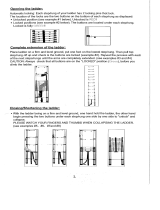
b) Open the runner by pressing the left bottom pin and pulling apart both
body sides of the runner simultaneously.
c) While lifting the lever, tilt the runner so the runner is parallel and close to
the safety rail.
d) Push together the two body parts of the runner until the left bottom pin
pops out. You will hear a click sound.
e) Make sure the runner is locked correctly by pulling the lever
downwards and confirming that the runner locks on the rail.
f) Climb the ladder keeping a distance of minimum 10 cm between torso
and ladder. This distance guarantees an optimal operation, enhanced
safety and better climbing ergonomics.
g) During ascent or descent, keep a minimum distance of 6 meters
between each user.
If the full body harness becomes loose during ascent or
descent, it should be correctly adjusted again from a secured
position.
Each rail section shall only be used by one user at a time, since
having more users using the same rail section simultaneously
would jeopardise its structural resistance.
Engaging the release mechanism of the runner during ascent or de-
scent can jeopardise the function of the braking mechanism.
The FPS is only approved as a fall arrest safety when ascending or
descending the ladder. Thus, the FPS shall never be used for work
positioning or for securing equipment. If work positioning at the ladder
is required, a separate dedicated and approved work positioning
equipment shall be used.
7.1.2 Releasing the Runner 2000/2002 from the safety rail
a) Before stepping in or stepping off the ladder, attach alternative
fall protection.
Before releasing the runner from the rail, ensure that you are
in a safe area (ground level) or attached to an alternative fall
protection.
Before releasing the runner from the rail, ensure that the run-
ner is without load and that there is no risk of falling.
Before releasing the runner from the rail, ensure that it is at-
tached to the D-ring marked “A” of the body harness in order
to avoid dropping it.
b) Release the runner from the rail by pressing the left bottom pin and
pulling the runner body parts apart simultaneously.
c) Remove the runner from the rail. It is not intended to be parked on the
rail. The runner is personal and shall be in reach in case of an emergency.
If any damages or faults are found during operation, or any
other circumstance which may jeopardise safety: immediately
stop the work in progress, and contact the site responsible,
e.g. the turbine owner or the site foreman.
7.2 Instructions for use of Eagle
DS
Runner
The cautions listed previously for Runner 2000/2002 are
equally applicable to Eagle
DS
Runner. Follow them closely.
7.2.1 Attaching the Eagle
DS
Runner to the safety rail
a) Pull out the plunger and rotate the locking lever downwards (see
images below).
STOP
STOP
STOP
STOP
STOP
MASTER 47840008 EN_CORREGIDO.indd 13 25/10/17 12:01

14
b) Open the runner by pressing
the right button and pulling apart
both body sides of the runner
simultaneously.
c) Place the runner on the safety rail ensuring that the arrow on the plate
of the runner points upwards.
d) While lifting the lever, tilt the runner so the runner is parallel and close to
the safety rail.
e) Push together the two body
parts of the runner until the
push button pops out and you
hear a click.
f) Pull out the plunger and rotate the locking lever upwards (see images
below).
g) Make sure that the runner is locked correctly by pulling the lever
downwards and confirming that the runner locks on the rail.
h) Climb the ladder keeping a distance of minimum 10 cm between torso
and ladder. This distance guarantees an optimal operation, enhanced
safety and better climbing ergonomics.
i) During ascent or descent, keep a minimum distance of 6 meters
between each user.
Arrow
MASTER 47840008 EN_CORREGIDO.indd 14 25/10/17 12:01

15
7.2.2 Releasing the Eagle
DS
Runner from the safety rail
a) Pull out the plunger and rotate the lever downwards to the horizontal
position (see images below).
b) Press and hold the push button.
c) Open the runner by pressing the push button and by pulling apart both
body sides of the runner simultaneously (see image below).
d) Remove the runner from the safety rail.
8.1 Cautions
a) Keep all the parts free of oil, grease, paint, aggressive chemicals
and alike.
b) Clean the shock absorber using a weak sulpho-solution and a soft
brush. Subsequently, flush it with plenty of pure water.
c) Never place liquids or sharp objects in the vicinity of the FPS as
these might damage it.
d) If the FPS gets wet, dry the runner and the safety rail with a dry
cloth. Let the shock absorber air-dry naturally. Do not use any kind of
heating.
8.2 Storage
a) Store the runner system out of direct sunlight and protected from
heat and dust.
8.3 Annual inspection
a) At least every 12 months, a certified technician shall inspect the
FPS (both runner and rail). Otherwise, the warranty will be void and
AVANTI will renounce all liability and claims that may appear.
The annual inspection may only be conducted by a certied
technician.
The annual inspection shall be carried out following the inspection
procedure. During the inspection, the “Annual Inspection Check-
list” Appendix and the “Inspection log sheet” Appendix shall be
lled in for future reference.
b) During this inspection, special attention shall be paid to the safety
rail and the runner
8.4 Inspection procedure
8.4.1 Ladder rungs
a) Ensure that no dents, holes, or cracks have any influence on the
rung stability.
b) The dents shall not exceed 10 mm in diameter or be more than 1
mm deep.
c) If dents are found on the rung edges or corners, the step stability
can no longer be guaranteed. In such case, replace the ladder section.
8 Maintenance
STOP
STOP
Caution!
The locking lever is only to be used when locking or unlock-
ing/releasing the runner. In all other situations the locking
lever shall be kept in locked position xed with the plunger
locked in the runner body.
MASTER 47840008 EN_CORREGIDO.indd 15 25/10/17 12:01

16
8.4.2 Ladder stiles
a) Ensure that no dents, holes, or cracks have any influence on the stiles´
stability.
b) The dents shall not exceed 20mm in diameter or be more than 1 mm
deep.
c) If dents are found on the stile edges or corners, the stile stability can no
longer be guaranteed. In such case, replace the ladder section.
8.4.3 Flange connection kits
a) The distance between the rungs at tower flange connection shall be
minimum 255 mm and maximum 300 mm.
8.4.4 Ladder ends
a) On the top and bottom ends of the complete ladder system, a
protection guard (such as the AVANTI rubber feet or end cap) shall be put
in place on the stiles.
8.4.5 Safety rail
a) Ensure that the safety rail sections are mounted according to the
installation instructions of this manual.
b) Ensure that no sharp rail ends are present.
c) Check the legibility of the product marking. If marking is not present, a
certified technician shall replace them.
d) During the erection of the wind turbine towers, top and bottom rail-
stops shall be mounted on each individual tower section.
e) Ensure that top and bottom rail-stops are mounted.
8.4.6 Fish-joints
a) Ensure that the fish-joints are mounted with 4 hammerhead screws.
b) Ensure that the gap between consecutive safety rails is minimum 1mm
and maximum 4 mm.
c) Ensure that the indicator mark of each hammerhead screw and the
self-locking nuts are at an angle of 70º.
d) Make sure that all hammerhead screws and self-locking nuts of the rail
system are present and torqued to 8 Nm.
8.4.7 Circular inspection sticker
a) Ensure that the sticker is present and that the due date has not
expired.
8.5 Ordering spare parts
a) If any part of the FPS is found to be broken, unsafe or missing,
put the FPS out of service immediately.
b) Subsequently, contact an AVANTI representative to replace/
repair the missing parts.
c) Finally, a certified technician shall carry out an inspection
following the inspection procedure.
1
|
2
|
3
|
4
|
5
|
6
|
7
|
8
|
9
|
1
0
|
1
1
|
1
2
|
1
5
|
1
6
|
1
7
|
1
8
|
1
9
|
2
0
|
2
1
|
APPROVED
MASTER 47840008 EN_CORREGIDO.indd 16 25/10/17 12:01

MASTER 47840008 EN_CORREGIDO.indd 23 25/10/17 12:02

Australia
Avanti Wind Systems PTY LTD
Unit 7 / 109 Tulip Street, Cheltenham Melbourne VIC 3192
P: +61 (0) 3 9585 1852
China
Avanti Wind Systems
Building 4, No, 518,
Gangde Road, XiaokunshanTown
Songjiang District, 201614 Shanghai
P: +86 21 5785 8811 · F: +86 21 5785 8815
Denmark
Avanti Wind Systems A/S
Rønnevangs Allé 6 · DK-3400 Hillerød
P: +45 4824 9024 · F: +45 4824 9124
Germany
Avanti Wind Systems GmbH
Max-Planck-Str. 8 25335 Elmshorn
P: +49 (0) 41 21-7 88 85 – 0 · F: +49 (0) 41 21- 7 88 85-20
Spain
Avanti Wind Systems SL · Poligono Industrial Centrovia
Calle Los Angeles No 88 nave 1 · 50198 La Muela
P: +34 976 149524 · F: +34 976 149508
UK
Avanti Wind Systems Limited
Unit 2, Cunliffe Court Clayton-Le-Moors
Accrington BB5 5JG
P: +44 (0) 1254 399923
USA
Avanti Wind Systems, Inc.
11311 West Forest Home Ave. Franklin, Wisconsin 53132
P: +1 (262) 641-9101 · F: +1 (262) 641-9161
India
Avanti Wind Systems India (P) Ltd.
Old No. 28, New No. 41,
Vellala Street, Aiyanambakkam
Chennai 600095 · Tamil Nadu
P: +91 95 00 173 492
Brazil
Avanti Brasil Sistema Eólicos LTDA.
Rua João Paulo II, 131
Autódromo Eusébio, Ceará 61760-000
P: (+55) 85 9 9955-0090
I: www.avanti-online.com · E: [email protected]
47840008 - FPS manual EN
11
th
Edition: January 2017
Revision 3: 10/10/2017
MASTER 47840008 EN_CORREGIDO.indd 24 25/10/17 12:02
/