Tyco FP1600 Operating Instructions Manual
- Category
- Fire protection
- Type
- Operating Instructions Manual
This manual is also suitable for

LT0312
FP1600 / OMEGA 64
INSTALLATION AND
CONFIGURATION MANUAL
Site Name:
This manual should be left in the panel

- WARNINGS -
NZS4512 and the NZ Building Code contain important
requirements for the installation, commissioning, and testing
of fire alarm systems. You must comply with the requirements
of these documents, and any other statutory or regulatory
requirements, in addition to the information contained in
these instructions.
The FP1600 and OMEGA 64 Fire Alarm Systems
contain Static sensitive components.
Always observe appropriate ESD precautions
when handling any Printed Circuit Boards.
The heatsink of the Battery Charger
Regulator (U11) can get very hot when
under high load or charging a flat battery.
CAUTION
HOT
SURFACE
- DISCLAIMER -
This product provides a configuration facility via the Programming
Menu. This facility allows the user to define in detail the operation
of the system, and changes may be made which prevent the
system from meeting statutory or other requirements.
The manufacturer and supplier cannot accept any responsibility
as to the suitability of the functions generated by the user using
the programming facility.

OPERATING INSTRUCTIONS
FP1600 / OMEGA 64 is a 16 zone self-contained conventional fire alarm system expandable in multiples
of 16 zones to maximum of 96 zones. It has been designed specifically to meet NZS 4512:1997, the
New Zealand Building Code (Section F7), and the NZ Fire Service requirements for connection to remote
receiving stations.
Special features are: * Flexible programming facilities * Six zone circuit types
* Keypad circuit isolation * Automated Self-Test
* Serial Remote Displays (up to 8) * History log
Detector Compatibility – Refer to listings published elsewhere for detector compatibility.
Zone Circuits - The zone input circuits can be configured individually as one of the following types:
(All circuit types use a 2k70, 1% End of Line Resistor.)
Flowswitch - Open circuit is instant alarm. Short circuit is defect.
Default configuration: Non-Brigade signalling and Non-Bell ringing.
A globally programmable delay (0/5/10/15/20/25 seconds, default 5 seconds) applies before going into
alarm - the circuit must be continuously in alarm for the full period of the delay. A fixed delay of 5 seconds
continuously in normal applies before going out of alarm. This circuit type is non-latching.
Thermal - Open circuit is instant alarm. Short circuit is defect.
Default configuration: Latching, Brigade signalling, and Bell Ringing.
Evacuation Control - Supervised connection to a sprinkler DBA “Bell” output. (available on Master board
zone circuits 1-16 only). Short circuit is instant alarm. Open circuit is defect.
Default configuration is Non-Latching, Non-Brigade signalling, and Bell ringing.
An Evacuation circuit selected for bell ringing is unaffected by either of the Silence Alarms switches -
the alarm must be silenced at the source.
Combined - Allows connection of conventional 2-wire smoke detectors and clean contact devices.
Open circuit is instant alarm. Short circuit is defect.
Default configuration: Latching, Brigade signalling, Bell ringing, and smoke detector AVF enabled.
Smoke - Allows connection of conventional 2-wire smoke detectors and clean contact devices.
Open circuit is defect. Short circuit is an instant alarm if using programmable “MCP” facility.
(N/C contacts require PA0443 Contact conversion module).
Default configuration: Latching, Brigade signalling, Bell ringing, smoke detector AVF enabled, and “MCP”
option disabled.
Disabled - Shuts the circuits down to save current. Fitting an EOL resistor is optional on Disabled circuits.
LT0312 v1.03 4 July 2003 Page 1

Residential - Allows connection of conventional 2-wire smoke detectors and clean contact devices.
Open circuit is defect. Short circuit is an instant alarm if using programmable “MCP” facility.
(N/C contacts require PA0443 Contact conversion module).
Default configuration: “MCP” option disabled and smoke detectors Non-Brigade signalling, Non-Bell
ringing, Non-Indicating, AVF enabled.
The default configuration for “MCP” (if enabled): Latching, Brigade signalling, and Bell ringing.
A Residential circuit will latch a smoke detector activation in alarm for a per-board programmable period
(0-250 sec, default 30 sec, 0 = stay latched) before attempting to self-reset. This allows local sounders
to operate for the length of the delay per detector activation.
Smoke and thermal/MCP activations can be mapped separately to ancillaries, brigade, and bells.
Open circuit MCP alarm cannot be allowed on Residential circuits (i.e. combined operation) because
once a smoke detector had operated, an open circuit beyond the operated detector would not be able
to be detected. A contact conversion module (PA0443) is therefore required for MCPs.
7-Segment Displays - There are three 7-segment displays per board. See “Display Codes” later.
Zone Index LEDs - Single flash = thermal/manual alarm. Double flash = smoke alarm. The Normal LED
has a power-save cadence when mains is off.
Buzzer - The buzzer generally indicates the presence of abnormal conditions when the door is closed,
and the presence of defects when the system is not remotely connected.
Evacuation Switch - The Evacuation key switch allows manual activation of the alerting devices (without
calling the Brigade). It may also be programmed to activate ancillary outputs.
Silence Alarms Switch - Operation of the Silence Alarms switches (external or internal) prevents the
alerting devices sounding when an alarm is present. They may also be programmed to de-activate
ancillary outputs. The external keyswitch generates a defect.
Note: These switches will not silence the alerting devices for an Evacuation Control circuit alarm or the
ERD- input.
Services Restore Switch - The Services Restore switch is intended to allow the Brigade to restore
ancillary services even when an alarm is present. The effect of this switch on the ancillary outputs is
programmable.
Mains Switch - 230V Mains isolation is provided by a switch on the mains termination cover.
Brigade Interface - Fit a 2W/4W General Purpose SGD (PA0862), or a General Purpose Brigade Relay
Interface (PA0861). These boards mount on stand-offs and plug into the ”Brigade Signalling Interface”
Connector (J20) (Master board only). If an interface is not fitted, select “Local” mode (Lo) in programming.
RZDU Interface - Up to 8 compatible Remote Zone Display devices can be connected to the Master
board. Wiring is a 3 or 4-core star-spur arrangement. Refer to the Technical Manual for further details.
Brigade control switches and a Brigade index may be provided at each RZDU.
Page 2 4 July 2003 LT0312 v1.03

Control Buttons (internal) - Four pushbuttons give access to current and latched display information,
operator functions and to the programming facility (described later):
“Current Defects” shows all defects currently present.
“Latched Defects” shows all defects since last Panel Reset, including those currently present.
“System Status” shows current status conditions (including groups and switches).
“Function” gives access to the Function menu (see “Function Menu” and descriptions below).
In some menus, buttons have a slow/fast automatic increment mode if pressed and held.
Panel Reset - To clear latched conditions, modes, and indications, select Panel Reset (Pr) on the Function
Menu and press "Select".
Self-Test - Self-Test (St) is selectable on the Function menu. Press "Select" to commence test.
Self-Test automatically performs internal RAM and EEPROM checksum tests, and also exercises all
zone circuits. Order of testing (indication in brackets): (St), 1 - 8 Alarm (A), All Normal (n), 9 - 16 Alarm
(A), All Normal (n), All open-circuit (o), All Normal (n), then each enabled zone individually short-circuit
and back to normal (1), (2), (3) etc. to (16); (St) flashes until all RZDUs complete their test.
Self-Test failure results in a pulsing buzzer and failure code display (see “Self/Auto Test Failure Codes”)
Self-Test will not run (long beep) if there is a Fire or Defect indication (latched or current), or if a brigade
connected panel is not Brigade Isolated or in Brigade Test. Non-brigade calling zone circuits in off-
normal conditions are omitted from the test, but do not prevent it from running.
Automatic Test - An automatic version of the Self-Test runs at the beginning of every daily charger inhibit
period. This can be initiated manually by selecting "Ci" on the Function menu.
Lamp Test - To initiate a lamp test select (Lt) on the Function menu. Press any button to cancel.
The door may be closed during a lamp test.
Non-Latching Test (NLT) Mode - NLT (walk test) mode (nL) is selectable through the Function menu.
A double beep every thirty seconds and an "nL" displayed, indicates entry into this mode. All enabled
zone circuits are temporarily set to indicating, non-latching, bell-ringing, non-brigade calling, with no
delays or gating regardless of their programmed selection.
In NLT mode, when any circuit is placed into alarm, its zone indication is latched on with the most recent
type of alarm, and the evacuation (Bells) output is activated for 0.5 seconds. Groups and ancillaries do
not operate.
A long beep indicates NLT mode cannot be entered - this could be a Fire or Defect condition (latched
or current), or if a brigade-connected panel is not Brigade Isolated or in Brigade Test. Panel Reset clears
NLT mode.
History Recall - History Recall is an interrogation feature available in the Function menu.
The most recent 15 significant events per board are stored in chronological order in RAM and will be
lost if power fails. There is no time/date "stamping". (See “Display Codes” for details of operation).
Zone Isolation - Individual zone isolation/de-isolation (toggle function) is available on a board-by-board
basis in the Function menu. Isolated zones are indicated on the displays. Power failure will clear.
LT0312 v1.03 4 July 2003 Page 3

Charger Inhibit - Starts a 40 minute Charger Inhibit period (reduced voltage). Also initiates an automatic
self-test (if permitted). Panel Reset will terminate period.
Bells Output - For supervision, all alerting devices must have a series diode (eg. 1N4004), and
End of Line resistors must be fitted as follows: 1 Branch: 9k1 1% EOL, 2 Branches: 2 x 18k 1% EOLs,
or 3 Branches: 3 x 27k 1% EOLs. Maximum total load is 5A (subject to battery / charger capacity
limitations). Supervision can be disabled in programming.
Three links (R62 - R64) can be cut out to convert to 5 Amp clean contact (supervision must be disabled).
Ancillary Relay (Ar) - The ancillary relay on each board is a 30V, 5A max (Resistive) single pole
changeover relay. Ar defaults to ”Common Fire or Lamp Test” but is fully programmable for other uses.
On-Board Ancillary Outputs (A20-, A21-) - Two hard-wire open collector output tabs on each board
default to "Common Defect or Lamp Test" and "Common Normal or Lamp Test" respectively, but are
programmable for other uses.
Additional Relay/Ancillary Outputs - Access per board to the other 19 ancillary outputs is via a 26
Way Flat Ribbon Cable (J21) and a Mimic Termination Board (PA0702). All Outputs are 30V, 200mA
open collector drivers (except LAMP- also drives the internal lamp).
All ancillaries are programmable, but defaults are suitable for a hard-wired mimic. (See “Ancillary Output
Defaults” for default functions and Output Designation on the Mimic Termination Board).
Defect Buzzer Cancel Input (DBC-) (Master board only) - A momentary closure to 0V silences the local
mode defect buzzer.
External Defect Input (Ext DEF-) - Pull this input to 0V to generate a defect.
External Reset Input (Ext RST-) (Master board only) - Pull this input to 0V to generate a Panel Reset.
Evacuation Relay Drive Input (ERD-) (Master board only) - Pull this input to 0V to activate the alerting
devices (non-silencable). (To comply with latest standards, use Evacuation Control Zone circuit instead).
Not implemented in V4.00 software
Battery Charger - The internal battery charger is constant voltage and current-limited (13.65V, 2A
nominal), temperature compensated to suit an internal 12V sealed lead-acid battery. Multiple chargers
may be operated in parallel. For standby capacity of battery and charger combinations, refer to the
Technical Manual for calculation methods.
Programming Mode - To enter programming mode, press and hold all three Master board "Program"
buttons (Select, Mode, and Change) for 3 short beeps and 1 long beep. Insert the "Data Program Enable"
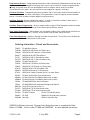
link in all boards if any changes are to be saved. Refer to "Programming Menu", “Programming Options
and Codes”, and the “Programming Flowchart” for options available.
Program Exit Options - If an "exit with save" is attempted with any of the "Data Program Enable" links
not installed, you will get a series of beeps and the system will remain in programming mode.
Simply insert the link(s) and try saving again, or press Function to bail out without saving any changes.
Programming mode times out after 4 minutes of inactivity, or by closing the door.
Page 4 4 July 2003 LT0312 v1.03

Ordering Information - Panels and Accessories
Programming Groups - A programming Group exists within a board only and becomes active only when
all zones on that board mapped to the group are in alarm and not isolated. Groups can optionally be
latching (until panel reset) and can be mapped to ancillary outputs and/or universal variables.
(For residential circuit types, any activated alarm type mapped to a group is sufficient).
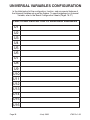
Universal Variables - Programming Universal Variables (U01-U16) can be driven and accessed by all
boards in the system, and allow some logical OR combinations of zone and group statuses between
boards. Universal Variables can be mapped to ancillary outputs.
Ancillary Override (System configuration option) - If Ancillary Override is enabled, “Door Open” is
treated the same as operating the Services Restore switch.
Ancillary Output Programming - Ancillary outputs follow a logical OR of the options selected, except
for overrides required by standards (eg. Evacuation overrides Silence Alarms)
Door Switch Supervision - (Master board only, not optional) When fitting a Mk3 Master board into an
older cabinet, solder a 220kW 1% resistor across the Services Restore switch terminals.
Earth Fault Monitoring - Detects a leakage from field wiring to earth. This facility can be disabled by
cutting out link R65 on all Mk3 boards in the system.
LT0312 v1.03 4 July 2003
Page 5
OMEGA 64 Masters have only 16 zones fitted. Extenders have no zone boards fitted.
Refer to LT0200 - "How to order FP1600 and OMEGA64" for more detailed information.
FP0547
FP0700
FP0640
PA0977
FA1371
FA1379
FP0548
FP0701
FP0641
KT0215
LM0074
KT0131
PA0702
LM0046
LM0049
LT0196
LT0312
RR0753
FA1372
FA1380
FA1209
PA0862
HW0036
FP1600 Rear Service
OMEGA 64 R/S Master (32 Zone index)
OMEGA 64 R/S Extender (16 Zone index)
OMEGA 64 Mk3 R/S Slave Board
OMEGA 64 R/S 32 Zone Master Index
OMEGA 64 R/S 16 Zone Extender Index
FP1600 Front Service
OMEGA 64 F/S Master (32 Zone index)
OMEGA 64 F/S Extender (16 Zone index)
OMEGA 64 Mk3 F/S Slave Board Set
OMEGA 64 Master to 1st Slave Loom
OMEGA 64 Comms Extender Kit for 2 or more Slaves
FP1600 16 Way Mimic Termination Board
I/O Board 26 Way Flat Ribbon Cable Loom (0.50m)
I/O Board 26 Way Flat Ribbon Cable Loom (0.25m)
FP1600/OMEGA 64 Technical Manual
FP1600/OMEGA 64 Installation/Configuration Manual
Circuit EOL Resistor (2k70 1%)
OMEGA 64 F/S 32 Zone Master Index
OMEGA 64 F/S 16 Zone Extender Index
FP1600 F/S Index FA1207 FP1600 R/S Index
GP SGD PA0861 GP Brigade Relay Interface
Door Key HW0213 Keyswitch Key

System States Alarms
Isolates
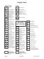
Display Codes
= Common Defect
= Normal
= Slave address not
set (Slave only)
= Charger Inhibited
(long test only)
= Panel Reset
in progress
= Program Enable
Link fitted
= Brigade Isolated
= Internal Silence
Alarms Switch on
= Brigade Test on
= Services Restore
Switch on
= Local Mode Defect
Silenced
= (Trial) Evacuation
Switch on
= Local Mode
= Non-Latching Test
mode on
= RZDU Services
Restore Switch on
= RZDU (Trial) Evac
Switch on
= Evac Relay Drive
input active
= Group n activated
(this board only)
= Flash Program
Enable Link fitted
= Bad Firmware
(not running)
= Zone nn Alarm
= Common Fire
= Residential Alarm
on Zone nn
= Batt Very Low Fire
(latched on power up)
= Zone nn Isolated
= Defect on Slave
Board
= Zone nn Defect
= Comms Fail Slave
Board n
= Foreign Slave
Board n
= Master Comms Fail
(Slave only)
= Defect at
RZDU n
= Comms Fail
RZDU n
= External Defect
at Master
= Evacuation Fault
= SGD Defect
= Battery Low
= Charger Fail
(Timeout Battery Test)
= Battery Connection Fault
= Earth Fault
Defects
= Foreign RZDU n
= (External) Silence
Alarms
= RZDU (External)
Silence Alarms
= Fuse Blown
= Hardware Fault
= Program Fail
= EEPROM Corrupt
= Program Corrupt
= RAM Corrupt
= Watchdog Reset
= Auto Test Fail (Followed
by Self Test failure code)
Press and hold
CURRENT DEFECTS
or LATCHED STATUS
buttons to view Defects
= Latched Defect
Present. Press
LATCHED STATUS
to view.
= System States
Present. Press
SYSTEM STATUS
to view.
= Operating with Old
Slave or old Master
Page 6 4 July 2003 LT0312 v1.03
= LED board fault
= (Door) Loom
Connection Fault

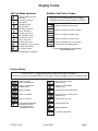
Self Test Mode Operation
= Checking Zone nn
individually for Short Circuit
= Checking all zones
return to normal
= If waiting for RDZUs
or slaves to finish
= Checking all zones
go into open circuit
= Fire from Slave Board
(Master only)
= Defect on Slave Board
(Master only)
= Auto Test Fail (this board only)
= Auto Test Fail on Slave Board
(Master only)
= Checking zones
go into Alarm
= Checking all zones
are normal
= Checking all zones
return to normal
= Self Test Mode running
(flashes)
Self/Auto Test Failure Codes
= Panel Reset performed
Immediately after Pr,
all zone abnormals
are logged to history
= Zone nn Normal
= Zone nn failed to go into alarm
History Events
= Zone nn failed to go back to normal
= Zone nn failed to go open circuit
= Zone nn failed to go short circuit
= Zone nn failed to stay normal while
another zone was being tested
= Zone nn Defect
= Zone nn Residential
Smoke Alarm
= Zone nn Isolated
= Zone nn Alarm
(MCP if Residential)
Press SELECT to step backwards through history (last 15 events)
To exit history, press any other button or close door. (History Mode will time out after 8 sec)
Display Codes
LT0312 v1.03 4 July 2003
Page 7
= Battery Very Low Fire
= System Power Up
= Watchdog Reset
= Last Event Displayed
Self Test Fail sounds buzzer (four beeps)
and displays failure mode code(s) as follows
Failure mode displays on board(s)
that had failure(s)
Self Test Pass returns to <base>

Page 8 4 July 2003 LT0312 v1.03
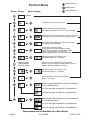
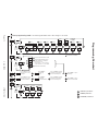
Button
Function Menu
Display
Button Display
Panel Reset and return to <base>
Self Test Mode running if permitted
Long Beep and Return to <base> if not permitted
<base>
Lamp Test On (LEDs flashing on, Buzzer on for 3 sec)
Pressing any key or a new alarm event will cancel
Non-Latching Test Mode if permitted (Pr to clear)
Long Beep if not Permitted
Enters History Display mode
Press SELECT to step backwards though
history (last 15 events). To exit History Mode
press any other button or close Door.
(History Mode will time out after 8 seconds)
SELECT toggles Zone isolate status
(RH decimal point on = isolated)
Starts 40 minute Charger Inhibit period
Returns to <base>
Displays application software version and Checksum
n.nn is software version
Steps through
isolate status
on all 16 zones
SELECT toggles Zone isolate status
(RH decimal point on = isolated)
cc is first two digits of checksum (in Hexadecimal)
dd is last two digits of checksum (in Hexadecimal)
Displays bootloader software version and Checksum
n.nn is software version
cc is first two digits of checksum (in Hexadecimal)
dd is last two digits of checksum (in Hexadecimal)
Zone range will be different on Slave boards
Board 2 (17-32), Board 3 (33-48), Board 4 (49-64)
Board 5 (65-80) and Board 6 (81-96)
Some options are not available on a Slave Board
SELECT Button
CHANGE Button
MODE Button

LT0312 v1.03 4 July 2003
Page 9
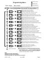
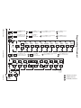
Button
Programming Menu
Display Button Display
SELECT Button
CHANGE Button
MODE Button
Press and hold the SELECT, MODE and CHANGE buttons on the Master Board
to enter Programming Mode (system will make 3 short and 1 long beeps).
Fit the "Data Program Enable" link in all boards if any changes are to be saved
Step through Zones to Configure
Change or Toggle Zone Configuration Option
Select Zone Configuration Options
Step through Zones to map to Ancillaries
Change or Toggle mapping of Zone to selected Ancillary
Select the Ancillary to map to (Ar, A20, A21, A1-A19)
Step through Zones to map to Groups
Toggle mapping of Zone to selected Group
Select the Group to map to (G1-G8)
Step through Zones to map to Universal Variables
Toggle mapping of Zone to selected Universal Variable
Select the Universal Variable to map to (U1-U16)
Step through Groups to configure
Change or Toggle Group Configuration Options
Select Group Configuration Options
Step through Groups to map to Ancillaries
Toggle mapping of Group to selected Ancillary
Select the Ancillary to map to (Ar, A20, A21, A1-A19)
Step through Groups to map to Universal Variables
Toggle mapping of Group to selected Universal Variable
Select the Universal Variable to map to (U1-U16)
Step through Ancillaries to Configure
Change or Toggle Ancillary Configuration Options
Select Ancillary Configuration Options
Step through Ancillaries to map from Universal Variables
Toggle mapping from selected Universal Variable
Select the Universal Variable to map from
Change or Toggle System Configuration Options
Step through System Configuration Options
Go back to top of menu (no change)
Reload defaults (return to --)
Deselect reload defaults (toggle back to --)
Save values and Exit
Note:
Groups are local to each board
Ancillaries are local to each board
Universal variables are shared across the system
The select button returns to the top menu level at the end of
each sub-menu list. eg. SELECT steps through the Ancillary
list (Ar, A20, A21, A1, A2 ... ... A18, A19) and after A19 will step
back out to Anc and on to A-U etc. If, however, the SELECT
button is pressed and held, it will continue to cycle through the
sub-menu list until the button is released.

Page 10 4 July 2003 LT0312 v1.03
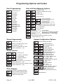
Programming Options and Codes
Zone Programming
Circuit Type
= Disabled
= Zone Number nn
Circuit Type
= Thermal
Circuit Type
= Smoke
Circuit Type
= Combined
Circuit Type
= Flowswitch
Circuit Type
= Residential
Circuit Type
= DBA/Evacuation
(Master board only)
= Callpoint or none
(S, rE only. Enables MCP band)
= Gated or not
(S, Co, rE only)
= Latching or not
nb = nothing calls brigade
Cb = Non residential only calls brig
b = All alarms call brigade
Zone and Zone Mapping Options
S = residential smoke alarm on Zone LED
nS = residential smoke alarm Not on LED
= Low / High Power
(FL, th, Ec only)
= Zone maps to Ancillary
(Ar,A1-A21)*
(Centre decimal on = yes)
= Zone maps to Group
(G1-G8)*
(Centre decimal on = yes)
* for rE zones:
Ar, An, Gn, Unn decimal as follows:
LH decimal on = yes for Smoke
Centre decimal on = yes for MCP
System Configuration Options
System Configuration Menu
Brigade connected
or Local Mode (Master)
Evac Monitor
enabled / disabled
Ancil Override (Global)
enabled / disabled
Flowswitch Delay (Global)
(note decimal point)
0./5./10./15./20./25. sec
Adjust Batt Low Volts
in 0.1V steps (Master only)
P3 = 12.2V + 0.3V
-2 = 12.2V - 0.2V
Residential Delay (per board)
1 - 25 (x 10) sec
0 = latch
Number of RZDUs
rd0 = none
rd1 - rd8 are valid
Exit Programming Mode (Master only)
Reload Defaults
nr = nothing rings bells
Cr = Non residential only rings bells
r = All alarms ring bells
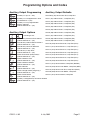
Group Programming
Group Options
= Latching or not
nr = Doesn't ring bells
r = Rings bells
nb = Doesn't call brigade
b = Calls brigade
= Group maps to Ancillary nn (Ar, A1-A21)
(Centre decimal on = yes)
= Group n (G1 - G8)
= Group n is mapped from a zone
(LH decimal on = yes)
= Group n is mapped to an output
(Centre decimal on = yes)
= Zone maps to Universal Variable (U1-U16)*
(Centre decimal on = yes)
= Group maps to Universal Variable (U1-U16)
(Centre decimal on = yes)
Slave Displays
Slave enters programming mode
at board number program position
Displayed at slave when program
changes are being saved
Number of boards in System
or board number if Slave
to disable (Slave)

LT0312 v1.03 4 July 2003
Page 11
Programming Options and Codes
= Forced on by External Evac Switch?
(Centre decimal on = yes)
Ancillary Output Programming
= Ancillary nn (Ar, A1 - A21)
Ancillary Output Options
= Latching or not
= Ancillary nn is mapped from a zone
(LH decimal on = yes)
= Ancillary nn has programmable
options selected
(Centre decimal on = yes)
= Forced off by Silence Alarms Switch?
(Centre decimal on = yes)
= Forced off by Services Restore?
(Centre decimal on = yes)
= Forced on by Lamp Test?
(Centre decimal on = yes)
= Follow Evacuation (bells) Relay?
(Centre decimal on = yes)
= Follow Common Fire?
(Centre decimal on = yes)
= Follow Common Defect?
(Centre decimal on = yes)
= Follow Normal?
(Centre decimal on = yes)
= Follow Charger Inhibit (long only)?
(Centre decimal on = yes)
= Follow Panel Reset?
(Centre decimal on = yes)
Ancillary Output Defaults
Ancil Relay (Ar) ON for Com Fire, Lamp Test
Ancil 1 (A1) ON for Zone 1, Lamp Test (Z1-)
Ancil 2 (A2) ON for Zone 2, Lamp Test (Z2-)
Ancil 3 (A3) ON for Zone 3, Lamp Test (Z3-)
Ancil 4 (A4) ON for Zone 4, Lamp Test (Z4-)
Ancil 5 (A5) ON for Zone 5, Lamp Test (Z5-)
Ancil 6 (A6) ON for Zone 6, Lamp Test (Z6-)
Ancil 7 (A7) ON for Zone 7, Lamp Test (Z7-)
Ancil 8 (A8) ON for Zone 8, Lamp Test (Z8-)
Ancil 9 (A9) ON for Zone 9, Lamp Test (Z9-)
Ancil 10 (A10) ON for Zone 10, Lamp Test (Z10-)
Ancil 11 (A11) ON for Zone 11, Lamp Test (Z11-)
Ancil 12 (A12) ON for Zone 12, Lamp Test (Z12-)
Ancil 13 (A13) ON for Zone 13, Lamp Test (Z13-)
Ancil 14 (A14) ON for Zone 14, Lamp Test (Z14-)
Ancil 15 (A15) ON for Zone 15, Lamp Test (Z15-)
Ancil 16 (A16) ON for Zone 16, Lamp Test (Z16-)
Ancil 17 (A17) ON for Normal, Lamp Test (NORM-)
Ancil 18 (A18) ON for Com Defect, Lamp Test (DEF-)
Ancil 19 (A19) ON for Com Fire, Lamp Test (FIRE-)
Ancil 20 (A20) ON for Com Defect, Lamp Test
Ancil 21 (A21) ON for Normal, Lamp Test
= Ancillary is mapped to by Universal Variable
(Centre decimal on = yes)

Page 12 4 July 2003 LT0312 v1.03
Programming Flowchart
Call
Point
Gate Latch Brigade
toggles toggles toggles
Ring
Bells
toggles toggles
Resid.
LED
Thermal
Mode
steps steps
th, FL and
Ec ONLY
= SELECT pushbutton
= MODE pushbutton
= CHANGE pushbutton
Circuit Type
Enter programming mode Fit ”Data Program Enable” link to allow changes to be saved.
Press
to step
thru all
Zones
Press
to step
thru all
Zones
Press SELECT to step
through zones to map
to Groups
Press MODE to
step through
Groups
Press CHANGE to change
mapping. See Z-A above
for zone and rE options.
Press MODE to step to
next Group
steps through mapping options:
Centre decimal on = mapped
For rE zones only:
LH decimal on = yes for Smoke
Centre decimal on = yes for MCP
steps thru Ar, A20, A21, A1 - A19
Residential Circuits Only
Press SELECT to step
through zones to map
to Universal Variables
Press MODE to
step through
Universals Variables
Press CHANGE to change
mapping. See Z-A above
for zone and rE options.
Press MODE to step to
next Universal Variable
Press
to step
thru all
Groups
Latch Brigade
Ring
Bells
toggles
toggles toggles
Residential Circuits Only
steps

LT0312 v1.03 4 July 2003
Page 13
Programming Flowchart
= SELECT pushbutton
= MODE pushbutton
= CHANGE pushbutton
Latch
togglestogglestogglestogglestogglestogglestogglestogglestogglestogglestoggles
ON by
Evacuation
Switch ?
OFF by
Silence
Alarms ?
OFF by
Services
Restore ?
ON by
Lamp
Test ?
Follow
Evacuation
(Bells) Relay ?
Follow
Common
Fire ?
Follow
Common
Defect ?
Follow
Common
Normal ?
Follow
Panel
Reset ?
Follow
Charger
Inhibit ?
Centre decimal on = yes
Press
to step
thru all
Ancillaries
toggles
Brigade
Connected
or Local only
Evacuation
Supervision
enable/disable
toggles toggles
Ancillary
Override
enable/disable
Flowswitch Delay
steps steps
Battery Low
Voltage Adj.
steps steps steps
Residential
Delay
Number of
RDZUs
x10 seconds
0 = latch
No. of RZDUs
= 1- 8
0 = none
No. of boards
in System
1- 8 (Master)
0 to disable
on Slave
Number of
boards in
System
Reload
defaults
Save values
and exit
Press SELECT to step
through Ancillaries to map
from Universal Variables
Press MODE to
step through
Universal Variables
Press CHANGE to change mapping.
Centre decimal on = yes
Press MODE to step to
next Universal Variable
Press SELECT to step
through Groups to map
to Ancillaries
Press MODE to step
through Ancillaries
Press CHANGE to change mapping.
Centre decimal on = yes
Press MODE to step to
next Ancillary
Press SELECT to step
through Groups to map
to Universal Variables
Press MODE to
step through
Universal Variables
Press MODE to step to
next Universal Variable
Press CHANGE to change mapping.
Centre decimal on = yes

Page 14 4 July 2003 LT0312 v1.03
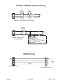
FP1600 / OMEGA 64 Zone Wiring
RZDU Wiring
+ANC
TX
0V
RX
FP1600 / OMEGA 64 RZDU
(other RZDUs star/spur)
Set
Address
(1-8)
+ANC
TX
0V
RX
AB
X
Manual
Call Point
RR
B
EOL
Heat
Detector
Thermal / Combined Circuit Wiring
Smoke
Detector
Smoke / Residential
Circuit Wiring
EOL
PA0443
Manual Call Point with PA0443
Black
Red
Yellow
ABX

LT0312 v1.03 4 July 2003
Page 15
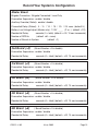
Master Board
Brigade Connection: Brigade Connected / Local Only
Evacuation Supervision: enable / disable
Ancillary Override (Global): enable / disable
Flowswitch Delay (Global): 0. / 5. / 10. / 15. / 20. / 25. secs (default 5.)
Battery Low Voltage Adjust (Master only): 12.2V ____ (P or -) (default = P0)
Residential Delay: seconds (0 = latch) (default = r03, 10 sec increments)
Number of RZDUs: (default rd0 = none)
Number of Boards in System: (default =1)
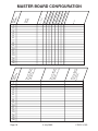
Record Your System's Configuration
2nd Board (=2)
(Board Number =0 to disable)
Evacuation Supervision: enable / disable
Residential Delay: seconds (0 = latch) (default = r03, 10 sec increments)
3rd Board (=3)
(Board Number =0 to disable)
Evacuation Supervision: enable / disable
Residential Delay: seconds (0 = latch) (default = r03, 10 sec increments)
4th Board (=4)
(Board Number =0 to disable)
Evacuation Supervision: enable / disable
Residential Delay: seconds (0 = latch) (default = r03, 10 sec increments)
5th Board (=5)
(Board Number =0 to disable)
Evacuation Supervision: enable / disable
Residential Delay: seconds (0 = latch) (default = r03, 10 sec increments)
6th Board (=6)
( Board Number =0 to disable)
Evacuation Supervision: enable / disable
Residential Delay: seconds (0 = latch) (default = r03, 10 sec increments)

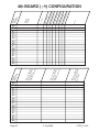
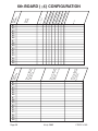
MASTER BOARD CONFIGURATION
Page 16 4 July 2003 LT0312 v1.03
Zones mapped
to the following
Ancillaries
(this board only)
Zone
Number
Zones mapped
to the following
Groups
(this board only)
Zones mapped
to the following
Universal
Variables
Cct Type
MCP (C/nC)
AVF Gating (G/nG)
Latching (L/nL)
Brigade (nb/Cb/b)
Ring Bells (nr/Cr/r)
Power (LP/HP)
Resid LED (S/nS)
Zone
Name
Zone
Number
Notes
1
2
3
4
5
6
7
8
9
10
11
12
13
14
15
16
1
2
3
4
5
6
7
8
9
10
11
12
13
14
15
16

LT0312 v1.03 4 July 2003
Page 17
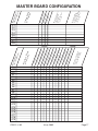
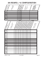
MASTER BOARD CONFIGURATION
Group mapped
to the following
Universal Variables
(centre decimal
on = yes)
G1
G2
Latching (L/nL)
Brigade (nb/b)
Bells (nr/r)
Group Name
or Function
Group Number
(this board only)
G3
G4
G5
G6
G7
G8
Group mapped to
the following
Ancillaries
(centre decimal
on = yes)
Forced on by Ext Evac?
A1
A2
Off by Ext Sil ALarms?
Off by Services Restore?
On by Lamp Test?
Follow Evac Relay?
Follow Common Fire?
Follow Common Defect?
Follow Normal?
Ancillary is mapped
to by the following
Universal Variables
Ancillary Name
or Function
Ancil Number
(this board only)
A3
A4
A5
A6
A7
A8
A9
A10
A11
A12
A13
A14
A15
A16
A17
A18
A19
A20
A21
Ar
Centre decimal on = yes
Follow Charger Inhibit?
Follow Panel Reset?
Mapped to by Universal?
Latching (L/nL)

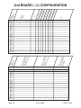
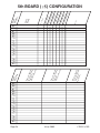
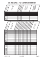
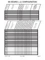
2nd BOARD ( ) CONFIGURATION
Page 18 4 July 2003 LT0312 v1.03
17
18
19
20
21
22
23
24
25
26
27
28
29
30
31
32
17
18
19
20
21
22
23
24
25
26
27
28
29
30
31
32
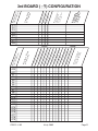
Zones mapped
to the following
Ancillaries
(this board only)
Zone
Number
Zones mapped
to the following
Groups
(this board only)
Zones mapped
to the following
Universal
Variables
Cct Type
MCP (C/nC)
AVF Gating (G/nG)
Latching (L/nL)
Brigade (nb/Cb/b)
Ring Bells (nr/Cr/r)
Power (LP/HP)
Resid LED (S/nS)
Zone
Name
Zone
Number
Notes
Page is loading ...
Page is loading ...
Page is loading ...
Page is loading ...
Page is loading ...
Page is loading ...
Page is loading ...
Page is loading ...
Page is loading ...
Page is loading ...
-
 1
1
-
 2
2
-
 3
3
-
 4
4
-
 5
5
-
 6
6
-
 7
7
-
 8
8
-
 9
9
-
 10
10
-
 11
11
-
 12
12
-
 13
13
-
 14
14
-
 15
15
-
 16
16
-
 17
17
-
 18
18
-
 19
19
-
 20
20
-
 21
21
-
 22
22
-
 23
23
-
 24
24
-
 25
25
-
 26
26
-
 27
27
-
 28
28
-
 29
29
-
 30
30


Tyco FP1600 Operating Instructions Manual
- Category
- Fire protection
- Type
- Operating Instructions Manual
- This manual is also suitable for
Ask a question and I''ll find the answer in the document
Finding information in a document is now easier with AI
Related papers
Other documents
-
Omega MID7000 Star 7 User manual
-
Scotts 71002-1 Installation guide
-
-
Brigade MD-50 (2581) Installation guide
-
-
Protocol 5872-2F 3D Puzzle Sky Liner User manual
-
Notifier Fire Panel User manual
-
Honeywell IFS-2600 User manual
-
Hellenbrand Reverse Osmosis Systems GRO Series User manual
-
 AV-GAD TFI-330 Installation guide
