Page is loading ...

500 Range
Multi-Fuel & Smoke Exempt
Wood Burning Stoves
500 Vista, 525 & 550 models
INSTALLATION & USER INSTRUCTIONS
(TO BE LEFT WITH THE CUSTOMER)
GB
IE

Page 2
525-500VISTA-I07-300719
CONTENTS
General Safety Notes
Page 2
Operating Instructions
Page 17
Installation instructions
Page 3
Wood Burning
Page 20
Chimney & Flue
Page 4
Solid Fuel Burning
Page 23
Flue Draught
Page 6
Technical Information
Page 24
Flue Stabiliser
Page 7
Maintenance
Page 26
Dimensions & Clearances
Page 7
Guarantee
Page 26
Installing the Stove
Page 11
Spare Parts
Page 27
Commissioning Checklist
Page 15
GENERAL SAFETY NOTES
Properly installed, operated and maintained, this appliance will not emit fumes into
the
dwelling. However
occasional fumes from de-ashing and re-fuelling may occur.
Persistent fume emission is potentially dangerous and must not be tolerated. If fume
emission does persist, open doors and windows to ventilate the room. Let the fire
burn out or eject and safely dispose of fuel from the
appliance. Once the fire is cold,
check the flue and chimney
for blockages and clean if required. Do not attempt to
relight the fire until the cause of the fume emission has been identified and
corrected. Seek expert advice if necessary
.
Do not fit an extractor fan in the same room as the appliance.
It is important that flue ways are cleaned frequently and the chimney swept regularly.
Also the stove must be maintained in good mechanical order. Regular sweeping
means
at least once a year for smokeless fuel and a minimum of twice a year for other
fuels.
If the chimney was previously used for an open fire, it is possible that the higher flue gas
temperatures generated by the stove may loosen deposits that were firmly adhering to
the inner surface of the chimney and cause blockage of the fluepipe. We recommend that
in such a situation a second sweeping of the chimney should be carried out within one
month of regular use of the stove after installation. Also, lock or remove any existing
dampers in the flue-way.
Should it be likely that children, aged or infirm people approach the fire, then a fireguard
should be fitted.
Avoid the use of aerosol sprays in the vicinity of the stove when it is in operation.
This appliance must be installed as per these instructions and regulations complied with.
No modifications or alterations of any kind are permitted.

Page 3
525-500VISTA-I07-300719
CLEAN AIR ACT 1993 AND SMOKE CONTROL AREAS
Under the Clean Air Act local authorities may declare the whole or part of the district of
the authority to be a smoke control area. It is an offence to emit smoke from a chimney
of a building, from a furnace or from any fixed boiler if located in a designated smoke
control area. It is also an offence to acquire an "unauthorised fuel" for use within a smoke
control area unless it is used in an "exempt" appliance ("exempted" from the controls
which generally apply in the smoke control area).
The Secretary of State for Environment, Food and Rural Affairs has powers under the Act
to authorise smokeless fuels or exempt appliances for use in smoke control areas in
England. In Scotland and Wales this power rests with Ministers in the devolved
administrations for those countries. Separate legislation, the Clean Air (Northern Ireland)
Order 1981, applies in Northern Ireland. Therefore it is a requirement that fuels burnt or
obtained for use in smoke control areas have been "authorised" in Regulations and that
appliances used to burn solid fuel in those areas (other than "authorised" fuels) have been
exempted by an Order made and signed by the Secretary of State or Minister in the
devolved administrations.
The 500 range has been recommended as suitable for use in smoke control areas when
burning dry wood logs in accordance with these instructions. Peat and other unauthorised
fuels must not be burnt in these appliances in smoke control areas.
Further information on the requirements of the Clean Air Act can be found here:
http://smokecontrol.defra.gov.uk/
Your local authority is responsible for implementing the Clean Air Act 1993 including
designation and supervision of smoke.
INSTALLATION INSTRUCTIONS
The installer has a responsibility under the Health and Safety at Work Act 1974 to
provide for the safety of persons carrying out the installation.
Attention is drawn to the fact that fire cement is caustic and hands must be washed
thoroughly after use.
The appliance is heavy and care must be taken during handling.
Although the appliance does not contain asbestos products, it is possible that
asbestos may be disturbed in existing installations and every precaution must be
taken.
These instructions give a guide for the installation of the appliance but in no way
absolves the installer from responsibilities to conform to British Standards, in
particular BS 8303 and BS EN 15287:2007, relating to the installation of solid fuel
appliances.
All local regulations, including those referring to National and European standards
need to be complied with when installing the appliance.
Permanent ventilation may be required in accordance with the guidelines given in
Approved Document J of The Building Regulations.

Page 4
525-500VISTA-I07-300719
It is essential that the fire has adequate air supply for combustion and ventilation.
Apertures provided for this purpose shall not be restricted.
CHIMNEY & FLUE
The successful operation of this appliance relies on the adequate performance of the
Chimney to which it is connected.
This Appliance is not suitable for installations in a shared flue system.
The chimney must:
Have an internal cross section of no less than 320cm² (Ø200mm). If a flue liner is
used it should be 125mm diameter (5") and suitable for solid fuel.
Be a minimum 4.5m high from hearth level to pot.
Be terminated at least 1m above roof level so that the chimney does not terminate
in a pressure zone (see Fig. 2).
Be free from cracks, severe bends, voids and obstructions.
Be connected to this one appliance only.
New chimneys must be tested in accordance with HETAS requirements.
If the stove is installed as a free standing appliance, it should not support any part of
the chimney.
Voids in the chimney should be avoided, as these will prevent a steady flue draught.
The stove flue pipe should pass beyond the narrowing of the chimney (see Fig. 1).
Consideration should be given to falling soot. For rear outlet stoves it may be
necessary to provide a soot catchment area in the flue pipe so that soot does not
settle in the path of the flue gases. The optional rear flue box attachment available
from ESSE has a detachable base that allows for soot to be removed (See Fig. 1).
A flue/chimney access point may also be required so that the state of the chimney
can be checked and any fallen soot removed.
External flues must be insulated to prevent heat loss.
CO Alarms
Building regulations require that whenever a new or replacement fixed solid fuel or
wood/biomass appliance is installed in a dwelling, a carbon monoxide (CO) alarm must be
fitted in the same room as the appliance, in accordance with BS EN 50292:2002. The
installation of an alarm must not be considered a substitute for either installing the
appliance correctly, or ensuring regular servicing and maintenance of the appliance and
chimney system.


Page 6
525-500VISTA-I07-300719
FLUE DRAUGHT
The chimney can be checked, before the stove is installed, with a smoke match. If the
chimney doesn't pull the smoke it may suggest the chimney needs attention (see the Flue
Diagnosis Table, below).
This test is only a guide as an apparently poor flue may improve once
the stove is installed, lit and the flue is warmed. If, once the stove is
installed, there is any doubt that the chimney is providing an adequate
draught; a flue draught reading can be taken with the stove lit. Two flue
draught readings should be taken, one with the stove at minimum rate
and one at maximum rate.
MEASUREMENTS
The flue draught test hole is located on the right hand side of the stove at the back near
the top. Remove the screw to allow reading to be taken, replace the screw once readings
are complete.
MINIMUM
The stove should be lit and allowed to warm the flue thoroughly. The air controls can then
be set so that the stove burns on a low setting. Allow the burning rate to become steady.
The flue draught reading should now be taken with the primary air intake closed and the
secondary air control fully open.
MAXIMUM
The primary air intake can now be opened to allow the stove to burn at maximum rate.
Give the stove some time for the burning rate to become steady and then close the
primary air intake, make sure the secondary air control is fully open and take a flue
draught reading immediately. Ideally, the flue draught reading should range between
1mm wg (10 Pa) and 2.5mm wg (25 Pa). Any readings significantly outside this range may
indicate the need for remedial action.
Low flue draught symptoms: difficult to light and smoke coming into the room.
CAUSE
REMEDY
Cold chimney
Line the chimney
Chimney too short
Extend the chimney
Down draught
Relocate/extend chimney terminal. Fit an anti-down draught
cowl
Chimney diameter too large
Line the chimney
Chimney obstruction
Clear/sweep the chimney
Restricted air supply
Check for competing draughts (other chimneys, extractor
hoods/fans) - Fit an air vent if the room is sealed
High flue draught symptoms: fire difficult to control, fuel will not last, stove too hot, stove damage, chimney fire,
stove whistles whilst in operation.
CAUSE
REMEDY
External wind conditions combined with
chimney terminal
Fit stabiliser cowl
Fit flue draught stabiliser

Page 7
525-500VISTA-I07-300719
FLUE STABILISER
A flue stabiliser can be fitted to reduce the draught through the stove if the flue draught
is too high. The flue stabiliser should be:
Fitted in the same room as the stove.
The same size as the flue pipe.
Fitted no closer than 700mm to the flue outlet of the appliance.
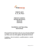
DIMENSIONS & CLEARANCES
Fig.3-550 Stove Dimensions

Page 8
525-500VISTA-I07-300719
Fig.4- 525 Stove Dimensions

Page 9
525-500VISTA-I07-300719
Fig.5 – 500-Vista Stove Dimensions

Page 10
525-500VISTA-I07-300719
Fig.6 – 500-Vista Stove with Log Box Dimensions

Page 11
525-500VISTA-I07-300719
INSTALLING THE STOVE
POSITIONING
The overall dimensions of the stove are shown in Fig. 3 and 4 along with a table that
indicates recommended distances between the stove and surrounding combustible
materials. As a rule, any surrounding combustible material should not exceed 80°C. There
should be sufficient space around the stove for service work.
HEARTH
The construction of the hearth must conform to Building Regulations, must be firm, non-
combustible and capable of supporting the stove. (Refer to Building Regulations
Document J).
FLUE CONNECTION
The flue pipe used to connect the stove to the chimney is 125mm (5") in diameter. The
stove is supplied ready for top flue connection. To change to a rear connection, a cast rear
flue collar kit or a rear flue box kit is available from www.esse.com. The flue blanking plug
supplied with the kits is used to block the top flue outlet. The blanking plate in the rear of
the stove must then be removed (to access the bolts attaching the blanking plate, the
convector panel must first be removed) - see Fig. 7. The rear flue box attachment allows
the stove to be installed further out of any building recess. Fig. 1 shows suitable flue
connections.
IMPORTANT INSTALLATION NOTES
1. The installation must allow for adequate chimney sweeping.
2. Avoid using bends greater than 45° to the vertical. All flue pipe sections should be as
close to vertical as possible.
3. All joints in the flue system must be effectively sealed.
4. All flue sockets must face upwards.
5. Check the appliance for soundness of seals between castings and main components
and that all supplied parts and fittings are correctly fitted.
On completing the installation, check that all the internal components of the stove are
positioned correctly.
Check - Ashpan, iron grate, baffle, side and back bricks.
Leave the appliance operational and explain the operation of the stove to
the customer. Leave all instructions and operating tools with the
customer.

Page 12
525-500VISTA-I07-300719
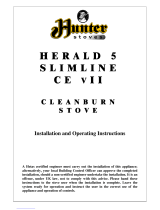
If rearrangement of the flue outlet connection is needed it must be
made before the stove is positioned in the fireplace.
Fig.7 –500-Vista can be arranged for top or rear flue outlet.
500-Vista Stove rear flue connection conversion.
The stove is supplied ready for a top flue connection.
1. Unfasten the flue blanking plate.
2. Using the same bolts fasten either the optional Cast flue collar or Rear
flue box.
3. Open the stove door and remove the baffle.
4. Fit the top flue blanking plug and attach the flue blanking bar.
5. The stove is now ready for a rear flue connection.

Page 13
525-500VISTA-I07-300719
Fig.8 –525 Arranging the flue for top or rear outlet.
525-Stove rear flue connection conversion.
The stove is supplied ready for a top flue connection.
1. Open door and remove baffle and back bricks.
2. Unfasten the nuts holding the stove lid down.
3. Remove the cast flue collar.
4. Remove the flue blanking plate.
5. Fit the flue blanking plate to the top of the stove.
6. Re-fit the stove top and tighten.
7. The stove is supplied with a stove top blanking disc. The screws in the
flue blanking plate can be adjusted so that the stove top blanking disc can
sit flush with the top.
8. Fit the cast flue collar to the rear of the stove.
9. Re-fit the rear and baffle bricks.
10. The stove is now ready for a rear flue connection.

Page 14
525-500VISTA-I07-300719
Fig.9 –550 Arranging the flue for top or rear outlet.
525-Stove rear flue connection conversion.
The stove is supplied ready for a top flue connection.
1. Open door and remove baffle and back bricks.
2. Unfasten the nuts holding the stove lid down.
3. Lift of stove lid.
4. Remove rear heat shield.
5. Remove the cast flue collar.
6. Remove the flue blanking plate.
7. Fit the flue blanking plate to the top of the stove.
8. Re-fit the stove top and tighten.
9. The stove is supplied with a stove top blanking disc. The screws in the flue
blanking plate can be adjusted so that the stove top blanking disc can sit flush
with the top.
10. Fit the cast flue collar to the rear of the stove.
11. Remove the knock out panel from the rear heat shield.
12. Re-fit the rear heat shield.
13. Re-fit the rear and baffle bricks.
The stove is now ready for a rear flue connection.

Page 15
525-500VISTA-I07-300719
COMMISSIONING CHECKLIST
To assist with any potential guarantee claim please complete the following information:-
To be completed by the installer.
Dealer the appliance was purchased from:
Name:
Address:
Telephone No:
ESSENTIAL information:
Date Installed
Model Description:
Serial No:
Installation Engineer:
Company Name:
Address:
Telephone No:
Commissioning Checks – to be completed and signed:
Is the flue system correct for this appliance?
Yes
No
Flue swept and checked for soundness?
Yes
No
Smoke test completed on installed appliance?
Yes
No
Spillage test complete?
Yes
No
Has the use of the appliance, operation and controls been
explained?
Yes
No
Clearance to combustible materials checked?
Yes
No
Instruction book handed to the customer?
Yes
No
CO Alarm fitted?
Yes
No
Signature:……………………………………………….. Print Name:………………………………………………….

Page 16
525-500VISTA-I07-300719
Net Efficiency:
Comments / Installation / Handover Instruction:
ESSE Engineering Ltd.
A+
Manufacturer Name:
Model Name:
Energy Efficiency Class:
Product Fiche
Energy Labelling Directive - (EU) 2015/1187 for Solid Fuel Boilers and
packages of solid fuel boilers, supplementary heaters, temperature
controls and solar devices
500 Vista / 525 / 550
supplied by the same manufacturer. Please use additional cells
containing the information above for more than 1 appliance.
5.0
0.0
110.1
82.9
Nominal Heat Output to Room:
Nominal Heat Output to Water:
Seasonal Space Efficiency:
Note: The product fiche can cover a number of solid fuel boiler models

Page 17
525-500VISTA-I07-300719
OPERATING INSTRUCTIONS
Smoke Exempt stoves need to maintain an open air supply unlike a
standard Multi-Fuel stove. As such the stove will not shut down like a
standard Multi-Fuel Stove and is designed to continue to draw air so
that is can meet local authority clean air act regulations.
Over firing will damage you stove.
To maintain peak efficiency, your stove should burn approximately
1.0kg of well-seasoned wood per hour.
Your stove should not be used as an incinerator and only
recommended fuels shall be used.
Parts of the appliance, especially the external surfaces, will be hot to
touch when in operation and due care will need to be taken.
Additional loose parts supplied inside your stove include:
A Stove Mitt – For removing the ash pan, adjusting the primary and secondary air
controls and operating the door handle.
A Riddling Tool – For operating the riddling grate and lifting the ash pan in and out.
A Flue Blanking Plug – To blank the top flue outlet if the rear outlet is to be used.
Always use stove mitts when adjusting controls and opening or closing
the door.

Page 18
525-500VISTA-I07-300719
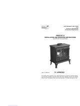
Fig.10 – Stove Controls
Fig.11-Riddling grate closed (wood burning).

Page 19
525-500VISTA-I07-300719
Fig.12-Riddling grate open (solid fuel burning).
RE-FUELLING ON TO A LOW FIRE BED
When adding new fuel to the stove, if there is insufficient burning fuel remaining in the
fire bed to light the additional fuel, you may experience excessive smoking, as the new
material struggles to light. This should be avoided by using additional kindling, if required.
FUEL OVERLOADING
Burning excessive amounts of fuel over a sustained period can damage your stove. With
this in mind, a maximum of 2kg of fuel should be added to the stove each hour.
OPERATION WITH DOOR LEFT OPEN
Operation with the door open can cause excess smoke. The appliance must not be
operated with the appliance door left open except as directed in the instructions.
DAMPERS LEFT OPEN
You may experience excessive smoking if too much air is allowed into the stove
throughout its use. With this in mind, the door, primary and secondary air controllers and
flue dampers should only be left open as directed within these instructions.

Page 20
525-500VISTA-I07-300719
WOOD BURNING
LIGHTING & CONTROLLING THE FIRE
Before lighting the fire ensure that all vermiculite bricks are in the correct position.
Close the primary air control and ensure the secondary air control is in the open position
by pulling the control out. Open the fire door and lay two logs along the base of the fire
box forming a space between them.
Fig.13-Logs laid in fire box.
Place a firelighter in the space and surround with a small amount of kindling. Lay a third
log over the top of the space perpendicular to the other logs.
/