
DESIGN + ENGINEERING
GROHE GERMANY
www.grohe.com
D
.....1
NL
.....6
PL
.....11
P
.....16
BG
.....21
CN
.....26
GB
.....2
S
.....7
UAE
.....12
TR
.....17
EST
.....22
.....27
F
.....3
DK
.....8
GR
.....13
SK
.....18
LV
.....23
RUS
.....28
E
.....4
N
.....9
CZ
.....14
SLO
.....19
LT
.....24
I
.....5
FIN
...10
H
.....15
HR
.....20
RO
.....25
EUROSMART
99.0333.031/ÄM 230805/12.14
25 168
25 170
English .....1
Français .....2
Español .....3

I
S.v.p remettre cette instruction à l'utilisateur de la robinetterie!
Entregue estas instrucciones al usario final de la grifería!
Please pass these instructions on to the end user of the fitting!
1
25 168
25 170
Page is loading ...
Page is loading ...

4
English
Application
Operation is possible in conjunction with:
- Pressurized storage heaters
Operation is not possible with:
- Low-pressure storage heaters
(displacement water heaters)
Specifications
• Flow rate at 45 psi flow pressure:
- Spout approx. 24 L/min or 6.3 gpm
- Handshower max. 7.5 L/min or 2 gpm
• Flow pressure
- min. 7.25 psi
- recommended 14.5 - 72.5 psi
- greater than 72.5 psi, fit with pressure reducing valves
• Max. operating pressure 145 psi
• Test pressure 232 psi
• Temperature
- max. (hot water inlet) 158 °F
- thermal disinfection possible
• Water connection cold - Right hand
hot - Left hand
Notes
- Installation of backflow protection must comply with local
codes and regulations.
- An access panel must be provided for access to diverter unit
and hose connections.
- Major pressure differences between cold and hot water
supply should be avoided.
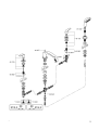
Installation
Layout dimensions to establish centers and proper clearances,
see dimensional drawings on page 1.
For deviation to the suggested installation, observe minimum
clearance required for escutcheon sizes.
Flush piping system prior and after installation of faucet
thoroughly!
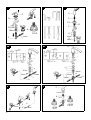
Side valves, see fig. [1] and [2].
• Valve with a groove on the top edge of the cartridge (A)
should be mounted on the right (cold water) side.
• Valve without a groove on the top edge of the cartridge (A)
should be mounted on the left (hot water) side.
1.Screw the mounting set (B) to the bottom of the thread of the
side valve (C).
Make sure that the rubber washer (B1) is on the top of the
metal washer (B2).
2.Insert the side valve (C) through the tub deck hole from
below.
3.Close the cartridges (clockwise for the hot side and counter-
clockwise for the cold side).
4. Place the escutcheon washer (D) on the deck tub and screw
down the handle with escutcheon (E) until it stops.
Be sure that the handle points away from the spout.
5. Tighten the mounting set (B) from below to secure the valve.
Handshower, see fig. [3].
1.Install the escutcheon (O1) onto the guide (O).
2.Install the guide (O) through the mounting surface, insure
the escutcheon O-ring (P) is in place.
3.Secure with mounting set (R).
4.Insert shower hose (S) through guide (O) from above.
5.Tighten the shower hose (S) to the handshower (U).
Spout (25 168), see fig. [4a].
1.Place the washer (I) on the tub deck and insert the spout (J)
from above.
2.Secure the spout with the mounting set (K).
3.Install t-pipe (L) to the spout.
4.Attach hoses (C2) onto the t-pipe (L).
Spout (25 170), see fig. [4b].
1.Place the washer (I) on the tub deck and insert the spout (J)
from above.
2.Secure the spout with the mounting set (K).
3.Install the diverter (L) to the spout, gently guiding the lift rod
assembly (M) up through the center of the spout (J).
4.Tighten the lift rod knob (N) to lift rod assembly (M).
5.Attach hoses (C2) onto the diverter (L).
Connect faucet, see fig. [5].
Connect the side valves to the water supply. Insure the
supplied washers are used for all connections.
The cold water supply should be connected on the right side
valve and the hot water supply to the left valve.
The shower hose (S) must be connected to the hose (C1).
Open cold and hot water supply and check connections
for leakage!
Maintenance
Inspect and clean all parts, replace as necessary and grease
with special grease.
Shut off cold and hot water supply!
I. Ceramic cartridge, see fig. [6].
1.Remove lever (F).
2.Unscrew the ceramic cartridge (A) using a 17mm wrench.
3.Change complete ceramic cartridge (A) or O-ring (A1).
Observe the different replacement part numbers of the
cartridges, see page 2.
II. Flow straightener, see page 2.
Unscrew and clean flow straightener (13 952).
III. Check valve, see fig. [5].
1.Disconnect hose (C1).
2.Remove check valve (V).
Assemble in reverse order.
Replacement parts, see page 2 ( * = special accessories).
Care
Instructions for care of this faucet will be found in the Limited
Warranty supplement.
Page is loading ...
Page is loading ...
Page is loading ...
Page is loading ...
Page is loading ...
Page is loading ...

2014/03/21
www.grohe.com
D
&
+49 571 3989 333
impressum@grohe.de
A
&
+43 1 68060
info-at@grohe.com
AUS
Argent Sydney
&
+(02) 8394 5800
Argent Melbourne
&
+(03) 9682 1231
B
&
+32 16 230660
info.be@grohe.com
BG
&
+359 2 9719959
grohe-bulgaria@grohe.com
CAU
CDN
CH
CN
&
+86 21 63758878
CY
CZ
&
+420 277 004 190
grohe-cz@grohe.com
DK
E
EST
F
&
+33 1 49972900
marketing-fr@grohe.com
FIN
&
+358 10 8201100
teknocalor@teknocalor.fi
GB
GR
&
+30 210 2712908
nsapountzis@ath.forthnet.gr
H
HK
I
IND
IS
J
KZ
LT
LV
&
+372 6616354
grohe@grohe.ee
MAL
&
+1 800 80 6570
info-singapore@grohe.com
N
&
+47 22 072070
grohe@grohe.no
NL
NZ
&
+09/373 4324
P
PL
RI
&
+62 21 2358 4751
info-singapore@grohe.com
RO
&
+40 21 2125050
info-ro@grohe.com
ROK
&
+82 2 559 0790
info-singapore@grohe.com
RP
&
+63 2 8041617
RUS
&
+7 495 9819510
info@grohe.ru
S
SGP
&
+65 6 7385585
info-singapore@grohe.com
SK
T
&
+66 2610 3685
info-singapore@grohe.com
TR
UA
&
+38 44 5375273
info-ua@grohe.com
USA
&
+1 800 4447643
us-customerservice@grohe.com
VN
&
+84 8 5413 6840
info-singapore@grohe.com
BiH
AL
HR
KS
ME
MK
SLO
SRB
&
+385 1 2911470
Eastern Mediterranean,
Middle East - Africa
Area Sales Office:
&
+357 22 465200
IR
OM
UAE YEM
-
 1
1
-
 2
2
-
 3
3
-
 4
4
-
 5
5
-
 6
6
-
 7
7
-
 8
8
-
 9
9
-
 10
10
-
 11
11
-
 12
12


GROHE 25168002 Installation guide
- Category
- Faucets
- Type
- Installation guide
Ask a question and I''ll find the answer in the document
Finding information in a document is now easier with AI
in other languages
- français: GROHE 25168002 Guide d'installation
- español: GROHE 25168002 Guía de instalación
Related papers
-
GROHE 25076EN0 Installation guide
-
GROHE Parkfield 25 153 User manual
-
-
-
-
-
-
-
-
Other documents
-
Barclay 4023-PL-CP Dimensions Guide
-
Hans Grohe 38040XX1 User manual
-
Danze D461723BN Installation guide
-
Gerber Versa 30" Slide Bar Assembly User manual
-
-
-
-
-
-