STEP 1 REMOVE PACKAGING
WARNING
Tip Over Hazard.
The refrigerator is much heavier at the top than at the
bottom—be careful when moving. When using a hand
truck, handle from the side only.
AVERTISSEMENT
Risque de
basculement Le réfrigérateur est beaucoup plus lourd en
haut qu’en bas. Il faut être prudent lors des déplacements. Si
un diable est utilisé, il faut soulever le réfrigérateur sur le côté
seulement.
ADVERTENCIA
Riesgo de Caídas
El refrigerador es mucho más pesado en su parte superior
que en su parte inferior – tenga cuidado al moverlo. Al usar
un carro manual, sosténgalo de costado únicamente.
• Carefully cut banding at the top and bottom, remove
the outer carton.
• Slide out the back corner posts (2).
• Slide the carton off the top of the cabinet.
NOTE: IT IS NOT NECESSARY TO LAY THE
CABINET DOWN IN ORDER TO REMOVE THE SKID!
Installation Instructions - Standard Installation
15
STEP 2 MOVE THE REFRIGERATOR
INTO THE HOUSE
• Re-use the corner posts from the packaging to protect
stainless steel models. Run the appliance dolly straps
over the posts and under the handles.
• Leave the protective film on the refrigerator until
installation is complete. IMPORTANT: Never lift the
refrigerator by the handle or push against the grille
panel; this could cause damage or misalignment.
• Avoid laying the unit on its back or side to prevent
sealed system restrictions.
STEP 3 INSTALL WATER LINE
WARNING
Connect to potable water supply
only.
AVERTISSEMENT
Raccordez l’appareil à une
alimentation d’eau potable seulement.
ADVERTENCIA
Realice la conexión a un
suministro de agua potable únicamente.
• A cold water supply is required for automatic
icemaker operation. The water pressure must be
between 40 and 120 p.s.i. (275-827 kPa).
• Route 1/4” OD copper or SmartConnect
™
plastic
tubing between house cold water line and the water
connection location.
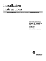
• The unit is secured to the
skid with 4 slotted tie-down
straps. Remove the six 7/16”
bolts from the base channels
in the tie-downs.
• Remove the six 7/16” bolts
securing the straps to the
skid.
NOTE: DO NOT ATTEMPT
TO ROLL UNIT OFF SKID.
• The support blocks on the
bottom of the refrigeration
case must be removed
before the refrigerator is taken off the skid or damage
will occur. Carefully tilt the refrigerator and slide the
blocks out from beneath.
• Remove the toekick and set aside for final installation.
• Lift the refrigerator off the skid with an appliance dolly.
Handle from the sides.
STEP 1 REMOVE PACKAGING (Cont.)
Remove
Tie Downs
Toekick
CONEXIÓN A TIERRA DEL
REFRIGERADOR
ADVERTENCIA
Riesgo de Descarga
Eléctrica
Si no se siguen estas instrucciones, se podrá producir la
muerte, incendios o descargas eléctricas.
El cable de corriente de este electrodoméstico cuenta con
un enchufe de 3 cables (conexión a tierra) que se conecta a
un tomacorriente de pared estándar de 3 cables (conexión
a tierra) para minimizar el riesgo de posibles descargas
eléctricas por parte del mismo.
Contrate a un electricista calificado para que controle el
tomacorriente y el circuito eléctrico, a fin de asegurar que el
enchufe esté correctamente conectado a tierra.
En caso de contar con un tomacorriente de pared de 2
cables, es su responsabilidad y obligación reemplazarlo
por un tomacorriente de pared de 3 cables correctamente
conectado a tierra.
NUNCA, BAJO NINGUNA CIRCUNSTANCIA,
CORTE NI ELIMINE EL TERCER CABLE
(TIERRA) DEL CABLE DE CORRIENTE.
NO USE UN ENCHUFE ADAPTADOR PARA
CONECTAR EL REFRIGERADOR A UN
TOMACORRIENTE DE 2 PATAS.
NO USE UN PROLONGADOR CON ESTE
ELECTRODOMÉSTICO.
31-49171 Rev. 2