Berkeley FN, SJH, PNS Shallow Well Jet Pumps/Tank Systems Owner's manual
- Category
- Water pumps
- Type
- Owner's manual

293 WRIGHT STREET, DELAVAN, WI 53115 WWW.BERKELEYPUMPS.COM
PH: 888-782-7483
owner's Manual
Shallow Well Jet Pumps/
Tank Systems
© 2013 Pentair, Ltd. All Rights Reserved. BE312 (Rev. 02/22/13)
Installation/Operation/Parts
For further operating, installation, or maintenance assistance:
Call 1-888-782-7483
558 0397
SJH
®
1537 0195
PNS
FN

Safety 2
READ AND FOLLOW
SAFETY INSTRUCTIONS!
This is the safety alert symbol. When you see this
symbol on your pump or in this manual, look for
one of the following signal words and be alert to the
potential for personal injury:
warns about hazards that will cause serious
personal injury, death or major property damage if
ignored.
warns about hazards that can cause serious
personal injury, death or major property damage if
ignored.
warns about hazards that will or can cause
minor personal injury or property damage if ignored.
The label NOTICE indicates special instructions which
are important but not related to hazards.
Carefully read and follow all safety instructions in this
manual and on pump.
Keep safety labels in good condition.
Replace missing or damaged safety labels.
California Proposition 65 Warning
This product and related accessories contain
chemicals known to the State of California to cause
cancer, birth defects or other reproductive harm.
ELECTRICAL SAFETY
Capacitor voltage may be hazardous.
To discharge motor capacitor, hold insulated handle
screwdriver BY THE HANDLE and short capacitor
terminals together. Do not touch metal screwdriver
blade or capacitor terminals. If in doubt, consult a
qualified electrician.
GENERAL SAFETY
Do not touch an operating motor. Modern
motors are designed to operate at high temperatures. To
avoid burns when servicing pump, allow it to cool for 20
minutes after shut-down before handling.
Do not allow pump or any system component to freeze.
To do so will void warranty.
Pump water only with this pump.
Periodically inspect pump and system components.
Wear safety glasses at all times when working on pumps.
Keep work area clean, uncluttered and properly lighted;
store properly all unused tools and equipment.
Keep visitors at a safe distance from the work areas.
Pump body may explode if used as a
booster pump unless relief valve capable of passing full
pump flow at 75 psi is installed.
WARNING
Hazardous pressure!
Install pressure relief
valve in discharge pipe.
Release all pressure on
system before working on
any component.
WARNING
Hazardous voltage.
Can shock, burn, or
cause death.
Ground pump before
connecting to power
supply. Disconnect power
before working on pump,
motor or tank.
Wire motor for correct
voltage. See
“Electrical” section of
this manual and motor
nameplate.
Ground motor before
connecting to power
supply.
Meet National Electri-
cal Code, Canadian
Elec tri cal Code, and
local codes for all
wiring.
Follow wiring
instructions in this
manual when
connecting motor to
power lines.

Table of Contents 3
Thank you for purchasing a top quality, factory tested pump.
Page
General Safety .....................................................................................................2
Warranty..............................................................................................................3
Installation ........................................................................................................4,5
Connecting Discharge Piping...............................................................................6
Electrical ........................................................................................................... 7,8
Preparing To Start The Pump ...............................................................................8
Troubleshooting ................................................................................................... 9
Repair Parts .................................................................................................10-13
Limited Warranty
BERKELEY warrants to the original consumer purchaser (“Purchaser” or “You”) of the products listed below, that they will be free
from defects in material and workmanship for the Warranty Period shown below.
Product Warranty Period
Water Systems:
Water Systems Products — jet pumps, small centrifugal pumps, submersible pumps and
related accessories
whichever occurs first:
12 months from date of original installation, or
18 months from date of manufacture
Pro-Source™
Composite Tanks 5 years from date of original installation
Pro-Source™ Steel Pressure Tanks 5 years from date of original installation
Pro-Source™ Epoxy-Lined Tanks 3 years from date of original installation
Sump/Sewage/Effluent Products
12 months from date of original installation, or
18 months from date of manufacture
Agricultural/Commer
cial:
Centrifugals – close-coupled motor drive, frame mount, SAE mount, engine drive, VMS, SSCX,
SSHM, solids handling, submersible solids handling
12 months from date of original installation, or
24 months from date of manufacture
Submersible T
urbines, 6” diameter and larger
12 months from date of original installation, or
24 months from date of manufacture
Our limited warranty will not apply to any product that, in our sole judgement, has been subject to negligence, misapplication,
improper installation, or improper maintenance. Without limiting the foregoing, operating a three phase motor with single phase
power through a phase converter will void the warranty. Note also that three phase motors must be protected by three-leg,
ambient compensated, extra-quick trip overload relays of the recommended size or the warranty is void.
Your only remedy, and BERKELEY’s only duty, is that BERKELEY repair or replace defective products (at BERKELEY’s choice). You
must pay all labor and shipping charges associated with this warranty and must request warranty service through the installing
dealer as soon as a problem is discovered. No request for service will be accepted if received after the Warranty Period has
expired. This warranty is not transferable.
BERKELEY SHALL NOT BE LIABLE FOR ANY CONSEQUENTIAL, INCIDENTAL, OR CONTINGENT DAMAGES WHATSOEVER.
THE FOREGOING LIMITED WARRANTIES ARE EXCLUSIVE AND IN LIEU OF ALL OTHER EXPRESS AND IMPLIED WARRANTIES,
INCLUDING BUT NOT LIMITED TO IMPLIED WARRANTIES OF MERCHANTABILITY AND FITNESS FOR A PARTICULAR
PURPOSE. THE FOREGOING LIMITED WARRANTIES SHALL NOT EXTEND BEYOND THE DURATION PROVIDED HEREIN.
Some states do not allow the exclusion or limitation of incidental or consequential damages or limitations on the duration of an
implied warranty, so the above limitations or exclusions may not apply to You. This warranty gives You specific legal rights and You
may also have other rights which vary from state to state.
This Limited Warranty is effective June 1, 2011 and replaces all undated warranties and warranties dated before June 1, 2011.
In the U.S.: BERKELEY, 293 Wright St., Delavan, WI 53115
In Canada: 269 Trillium Dr., Kitchener, Ontario N2G 4W5

Installation 4
REPLACING AN OLD PUMP
Hazardous voltage. Disconnect power to
pump before working on pump or motor.
Step 1. Drain and remove the old pump. Check the old
pipe for scale, lime, rust, etc., and replace it if
necessary.
Step 2. Install the pump in the system. Make sure that all
pipe joints in the suction pipe are air-tight as well
as water tight. If the suction pipe can suck air, the
pump will not be able to pull water from the well.
Step 3. Adjust the pump mounting height so that the
plumbing connections do not put a strain on the
pump body. Support the pipe so that the pump
body does not take the weight of piping or fittings.
You have just completed the well plumbing for
your new shallow well jet pump. Please go to
Page 6 for discharge pipe and tank connections.
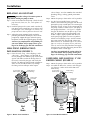
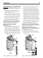
WELL POINT (DRIVEN POINT)
INSTALLATION (FIGURE 1)
Step 1. Drive the well, using “drive couplings” and a
“drive cap”. “Drive fittings” are threaded all
the way through and allow the pipe ends to butt
against each other so that the driving force of
the maul is carried by the pipe and not by the
threads. The ordinary fittings found in hardware
stores are not threaded all the way through
the fitting and can collapse under impact.
“Drive fittings” are also smoother than standard
plumbing fittings, making ground penetration
easier.
Step 2. Mount the pump as close to the well as possible
Step 3. Use the fewest possible fittings (especially
elbows) when connecting the pipe from the well
point to the pump suction port. The suction pipe
should be at least as large as the suction port on
the pump (include a check valve if your pump is
not equipped with one – see Figure 1). Support
the pipe so that there are no dips or sags in the
pipe, so it doesn’t strain the pump body, and
so that it slopes slightly upward from the well
to the pump (high spots can cause air pockets
which can air lock the pump). Seal the suction
pipe joints with PTFE pipe thread sealant tape.
Joints must be air- and water-tight. If the suction
pipe can suck air, the pump cannot pull water
from the well. If one well point does not supply
enough water, consider connecting two or three
well points to one suction pipe.
You have just completed the suction piping for
your new shallow well jet pump. Please go to
Page 6 for discharge pipe and tank connections.
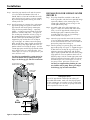
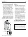
CASED WELL INSTALLATION, 2” OR
LARGER CASING (FIGURE 2)
Step 1. Mount the pump as close to the well as possible.
Step 2. Assemble the foot valve, strainer, and well pipe
(see Figure 2). Make sure that the foot valve
works freely.
To Household
Water System
Not
to
Scale
Pump Priming
Tee and Plug
Suction Pipe
From Well
Drive
Coupling
Drive
Point
Check
Valve
Priming
Tee and
Plug
Drive point
below water
level
2346 0396
Figure 1: Driven Point Installation
To Household
Water System
Pump Priming
Tee and Plug
Not
to
Scale
Check
Valve
10'
Min.
5–10'
Suction Pipe
From Well
Priming
Tee and
Plug
Foot
Valve
Sanitary
Well Seal
Well
Casing
2347 0396
Figure 2: Cased Well Installation

Installation 5
Step 3. Lower the pipe into the well until the strainer
is five feet above the bottom of the well. It
should also be at least 10 feet below the well’s
water level while the pump is running in order
to prevent the pump from sucking air. Install a
sanitary well seal.
Step 4. Install a priming tee, priming plug, and suction
pipe to the pump (see Figure 2). Connect the
pipe from the well to the pump suction port,
using the fewest possible fittings – especially
elbows – as fittings increase friction in the pipe
(however, include a foot valve – see Figure 2).
The suction pipe should be at least as large as
the suction port on the pump. Use PTFE pipe
thread sealant tape on threaded pipe joints.
Support the pipe so that there are no dips or
sags in the pipe, so it doesn’t strain the pump
body, and so that it slopes slightly upward from
the well to the pump (high spots can cause air
pockets which can air lock the pump). Seal the
suction pipe joints with PTFE pipe thread sealant
tape. Joints must be air- and water-tight. If the
suction pipe can suck air, the pump cannot pull
water from the well.
You have just completed the suction piping for
your new shallow well jet pump. Please go to
Page 6 for discharge pipe and tank connections.
INSTALLATION FOR SURFACE WATER
(FIGURE 3)
Step 1. The pump should be installed as close to the
water as possible, with the fewest possible fittings
(especially elbows) in the suction pipe. The
suction pipe should be at least as large as the
suction port on the pump.
Step 2. Assemble a foot valve and suction pipe (see
Figure 3). Make sure that the foot valve works
freely. Use PTFE pipe thread sealant tape on
threaded pipe joints. Protect the foot valve
assembly from fish, trash, etc, by installing a
screen around it (see Figure 3).
Step 3. Lower the pipe into the water until the strainer
is five feet above the bottom. It should also be
at least 10 feet below the water level in order to
prevent the pump from sucking air.
Step 4. Install a priming tee, priming plug, and suction
pipe to the pump (see Figure 3). Support the pipe
so that there are no dips or sags in the pipe, so
it doesn’t strain the pump body, and so that it
slopes slightly upward from the well to the pump
(high spots can cause air pockets which can air
lock the pump). Seal the suction pipe joints with
PTFE pipe thread sealant tape. Joints must be air-
and water-tight. If the suction pipe can suck air,
the pump cannot pull water from the well.
You have just completed the plumbing for your
new shallow well jet pump. Please go to Page 6
for discharge pipe and tank connections.
To Household
Water System
Pump Priming
Tee and Plug
Check
Valve
Not
to
Scale
Suction Pipe
From Well
10'
Min.
5–10'
Foot
Valve
Screen
Priming
Tee and
Plug
2348 0396
Figure 3: Surface Water Installation
Sealing Pipe Joints
Use PTFE pipe thread sealant tape for making all
threaded connections. Make sure that all pipe joints
in the suction pipe are air tight as well as water tight.
If the suction pipe can suck air, the pump will not be
able to pull water from the well.

Discharge Pipe and Pressure Tank Connections 6
PRE-CHARGE TANK CONNECTION
(FIGURE 4)
Step 1. Install two tees in the pump discharge port (see
Figure 4). The pipe size must be at least as large
as the discharge port.
Step 2. Run a pipe or reinforced hose from one arm of
the first tee to the port on the pre-charged tank.
Step 3. Connect the other end of the discharge tee to
your plumbing system.
Step 4. Check the pre-charge of air in the tank with an
ordinary tire gauge. The pre-charge should be
2 PSI less than the cut-in setting of the pump’s
pressure switch. The pre-charge is measured
when there is no water pressure in the tank. Your
new pump has a 30/50 PSI switch, so adjust the
tank pre-charge pressure to 28 PSI.
Congratulations! You have just completed the
tank connection for your jet pump.
Please go to Page 7 for electrical hookup.
STANDARD TANK CONNECTION
(FIGURE 5)
Step 1. Install one tee in the pump discharge port (see
Figure 5).
Step 2. Run a pipe from the pump discharge port to the
inlet port of your tank. The pipe size must be at
least as large as the discharge port.
Step 3. Remove the 1/8” NPT pipe plug from the pump
Air Volume Control (AVC) port (see Figure 5).
Run tubing from the pump’s AVC port (see Figure
5) to the port on the AVC mounted on the tank.
See instructions provided with tank and AVC for
details. AVC port location will vary, depending on
your pump model (see exploded view, Page 9).
Congratulations! You have just completed the
tank connection for your jet pump.
Please go to Page 7 for electrical hookup.
To Household
Water System
From
Well
Air Volume
Control
Air Volume
Control Tube
Pump
Priming Te e
and Plug
Pressure
Switch
2350 0396
Check
Valve
Figure 5: Standard Tank Connections
Wiring Chart – Recommended Wire and Fuse Sizes
Branch
DISTANCE IN FEET(METERS) FROM MOTOR TO SUPPLY
Max.
Fuse
0 - 100 101 - 200 201 - 300 301 - 400 401 - 500
Motor
Load
Rating
(0 - 30) (31 - 61) (62 - 91) (92 - 122) (123 - 152)
Model HP Volts Amp Amp AWG WIRE SIZE (mm
2
)
5FN-L 1/2 115/230 9.4/4.7 15/15 14/14(2/2) 10/14(5.5/2) 10/14(5.5/2) 6/14(14/2) 6/12(14/3)
7FN-L 3/4 115/230 12.4/6.2 20/15 12/14(3/2) 10/14(5.5/2) 8/14(8.4/2) 6/12(14/3) 6/12(14/3)
5PN, 05PNS11S 1/2 115/230 9.4/4.7 15/15 14/14(2/2) 10/14(5.5/2) 10/14(5.5/2) 6/14(14/2) 6/12(14/3)
7PN, 07PNS11S 3/4 115/230 12.2/6.1 20/15 12/14(3/2) 10/14(5.5/2) 8/14(8.4/2) 6/12(14/3) 6/12(14/3)
07SJH11C 3/4 115/230 14.8/7.4 20/15 12/14(3/2) 8/14(8.4/2) 6/14(14/2) 6/12(4/3) 4/10(21/5.5)
10SJH11C 1 115/230 19.2/9.6 25/15 10/14(5.5/2) 8/14(8.4/2) 6/12(14/3) 4/10(21/5.5) 4/10(21/5.5)
From Well
Pressure
Switch
To Household
Water System
Pump Priming
Tee and Plug
Check
Valve
2349 0396
Figure 4: Pre-charged Tank Connections

Electrical 7
Disconnect power before working on pump, motor, pressure switch, or wiring.
MOTOR SWITCH SETTINGS
Dual-voltage motors (motors that can operate at either
115 or 230 volts), are set at the factory to 230 volts. Do
not change motor voltage setting if line voltage is 230
volts, or if you have a single voltage motor.
NOTE: Never wire a 115 volt motor to a 230 volt line.
Remove Motor End Cover
If you have a dual-voltage motor, and will connect it to
115 volts, follow the procedure below.
You will need to remove the motor end cover to change
the voltage setting.
Your motor terminal board (located under the motor end
cover) should look like that shown below.
To change to 115 volts:
Step 1. Make sure power is off.
Step 2. Turn the dial counter-clockwise until 115 shows
in the dial window.
Step 3. The wires from the pressure switch should
already be attached to to power lead terminals.
Step 4. Reinstall the Motor end cover.
Pressure Switch Wiring
Step 5. Go to Wiring Connections below.
Hazardous voltage. Can shock, burn, or
kill. Connect ground wire before connecting power
supply wires. Use the wire size (including the ground
wire) specified in the wiring chart. If possible, connect
the pump to a separate branch circuit with no other
appliances on it.
Explosion hazard. Do not ground to a gas
supply line.
WIRING CONNECTIONS
Fire hazard. Incorrect voltage can cause
a fire or seriously damage the motor and voids the
warranty. The supply voltage must be within ±10% of
the motor nameplate voltage.
NOTICE: Dual-voltage motors are factory wired for 230
volts. If necessary, reconnect the motor for 115 volts, as
shown. Do not alter the wiring in single voltage motors.
Install, ground, wire, and maintain your pump in
compliance with the National Electrical Code (NEC) in the
U.S., or the Canadian Electrical Code (CEC), as applicable,
and with all local codes and ordinances that apply.
Consult your local building inspector for code information.
Figure 6: Removing Motor End Cover
Motor
End Cover
End Cover Screws
4693
Figure 8: Pressure Switch Wiring
Clamp the power cable to prevent strain
on the terminal screws.
Connect the green (or bare copper) ground wire
to the green ground screw.
Motor wires connect here.
3187 0704H
Power supply wires connect here.
230 Volt: Connect 2 hot wires (black and red)
here and cap the white (neutral) wire. It does
not matter which wire goes to which screw.
115 Volt: Connect one hot wire (black or red)
to one of these screws (it doesn't matter
which one). Connect the white (neutral) wire
to the other screw. Cap any remaining
black or red wires.
Figure 7: Voltage set to 230 volts, Dial Type
Voltage
Change Dial
Ground
Screw
Power Lead
Te rminals
4695

Electrical / Preparing to Start the Pump 8
Connection Procedure:
Step 1. Connect the ground wire first as shown in Figure
7. The ground wire must be a solid copper wire
at least as large as the power supply wires.
Step 2. There must be a solid metal connection between
the pressure switch and the motor for motor
grounding protection. If the pressure switch is
not connected to the motor, connect the green
ground screw in the switch to the green ground
screw under the motor end cover. Use a solid
copper wire at least as large as the power supply
wires.
Step 3. Connect the ground wire to a grounded lead in
a service panel, to a metal underground water
pipe, to a metal well casing at least ten feet (3M)
long, or to a ground electrode provided by the
power company or the hydro authority.
Step 4. Connect the power supply wires to the pressure
switch as shown in Figure 7.
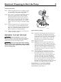
PREPARING TO START THE PUMP
Never run pump dry. Running pump
without water may cause pump to overheat, damaging
seal and possibly causing burns to persons handling
pump. Fill pump with water before starting.
Never run pump against closed discharge.
To do so can boil water inside pump, causing hazardous
pressure in unit, risk of explosion and possibly scalding
persons handling pump.
Step 1. Remove the priming plug from the priming tee
and fill the pump. Fill all piping between the
pump and the well and make sure that all piping
in the well is full. If you have also installed a
priming tee in the suction piping, remove the
plug from the tee and fill the suction piping.
Step 2. Replace all fill plugs.
Step 3. Power on! Start the pump. If you don’t have
water after 2 or 3 minutes, stop the pump and
remove the fill plugs. Refill the pump and piping.
You may have to repeat this several times in
order to get all the trapped air out of the piping.
A pump lifting water 25’ may take as long as 15
minutes to prime.
Step 4. After the pump has built up pressure in the
system and shut off, check the pressure switch
operation by opening a faucet or two and
running enough water out to bleed off pressure
until the pump starts. The pump should start
when pressure drops to 30 PSI and stop when
pressure reaches 50 PSI. Run the pump through
one or two complete cycles to verify correct
operation. This will also help clean the system of
dirt and scale dislodged during installation.
Congratulations on a successful installation.
If you were unsuccessful, please refer to the
Troubleshooting section (Page 9).
Fill pump
and piping
through
priming tee.
2351 0396
Figure 9: Prime the Pump

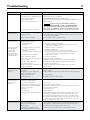
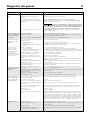
Troubleshooting 9
* (Note: Stop pump;
then check prime
before looking
for
other causes.
Unscrew
priming
plug and see if water
is in priming hole).
SYMPTOM POSSIBLE CAUSE(S) CORRECTIVE ACTION
Motor will not run Disconnect switch is off Be sure switch is on.
Fuse is blown or circuit breaker tripped Replace fuse or reset circuit breaker.
Starting switch is defective DISCONNECT POWER; Replace starting switch.
Wires at motor are loose, Refer to instructions on wiring (Page 7). DISCONNECT POWER; check and
disconnected, or wired incorrectly tighten all wiring.
Capacitor voltage may be hazardous. To discharge
capacitor, hold insulated handle screwdriver BY THE HANDLE and
short capacitor terminals together. Do not touch metal screwdriver
blade or capacitor terminals. If in doubt, consult a qualified electrician.
Pressure switch contacts are dirty DISCONNECT POWER and file contacts with emery board or nail file.
Motor runs hot and Motor is wired incorrectly Refer to instructions on wiring.
overload kicks off
Voltage is too low Check with power company. Install heavier wiring if wire size is too small
(See Electrical / Wiring Chart).
Pump cycles too frequently See section below on too frequent cycling.
Motor runs but no Pump in new installation did In new installation:
water is delivered* not pick up prime through:
1. Improper priming 1. Re-prime according to instructions.
2. Air leaks 2. Check all connections on suction line, AVC, and ejector with
soapy water or shaving cream.
3. Leaking foot valve or check valve 3. Replace foot valve or check valve.
Pump has lost prime through: In installation already in use:
1. Air leaks 1. Check all connections on suction line and shaft seal.
2. Water level below suction pipe inlet 2. Lower suction line into water and re-prime. If receding water level
in well exceeds 25’ (7.6M), a deep well pump is needed.
Foot valve or strainer is plugged Clean foot valve or strainer.
Ejector or impeller is plugged Clean ejector or impeller.
Check valve or foot valve is stuck shut Replace check valve or foot valve.
Pipes are frozen Thaw pipes. Bury pipes below frost line. Heat pit or pump house.
Foot valve and/or strainer are Raise foot valve and/or strainer above bottom of water source.
buried in sand or mud Clean foot valve and strainer.
Water level is too low for shallow well A deep well jet package may be needed (over 25 ft. to water)
setup to deliver water to deliver water.
Pump does not Water level in well is lower than A deep well jet will be needed if your well is more than 25’ (7.6M)
deliver water to full estimated depth to water.
capacity
Steel piping (if used) is corroded or Replace with plastic pipe where possible, otherwise with new steel pipe.
limed, causing excess friction
Piping is too small in size Use larger piping.
Packed well point Backflush well point or sink new point.
Pump delivers water but
Pressure switch is out of adjustment or DISCONNECT POWER; adjust or replace pressure switch.
does not shut off or contacts are welded together
pump cycles too
Faucets have been left open Close faucets.
frequently
Venturi, nozzle or impeller is clogged Clean venturi, nozzle or impeller.
Standard pressure tank is waterlogged Drain tank to air volume control port. Check AVC for defects. Check
and has no air cushion all connections for air leaks.
Pipes leak Check connections.
Foot valves leak Replace foot valve.
Air charge too low in pre-charged tank DISCONNECT POWER and open faucets until all pressure is relieved.
Using tire pressure gauge, check air pressure in tank at valve stem
located on the tank. If less than pressure switch cut-in setting (30-50
PSI), pump air into tank from outside source until air pressure is 2 PSI
less than cut-in setting of switch. Check air valve for leaks (use soapy
solution) and replace core if necessary.
Air spurts from faucets Pump is picking up prime When pump has picked up prime, it should pump solid water with no air.
Leak in suction side of pump Suction pipe is sucking air. Check joints for leaks with soapy water.
Well is gaseous Consult factory about installing a sleeve in the well
Intermittent over-pumping of well. Lower foot valve if possible, otherwise restrict pump discharge
(Water drawn down below foot valve.)

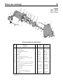
Repair Parts 10
1
2
3
4
5
6
7A
7B
16
16
10
9A
8
9
10
10
9B
11
12
13
14
15
2331 0296 BK
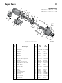
Exploded View
5FN / 5FN-L
7FN / 7FN-L
REPAIR PARTS LIST
• Not illustrated.
5FN 7FN
Key Part No. 5FN-L 7FN-L
No. Description Used 1/2 HP 3/4 HP
1 Motor 1 J218-582APKG J218-590PKG
2 Water Slinger 1 17351-0009 17351-0009
3 Seal Plate 1 N3-9 N3-9
4 Seal Plate Gasket 1 N20-35 N20-35
5 Shaft Seal 1 U109-6A U109-6A
6 Impeller 1 J105-40P J105-42P
7A Diffuser 1 L1-25P L1-25P
7B Diffuser Gasket 1 N20-34 N20-34
8 Barbed Fitting - Straight - 1/4” NPT 1 U111-211T U111-211T
9 Pump Body - Assembly 1 N176-38 N126-38F
9A Venturi (1) N32P-66 N32P-75
9B Nozzle (1) N34P-17 N34P-21
10 Pipe Plug - 1/4” NPT Hex Hd. 3 U78-941ZPV U78-941ZPV
11 Tube 3/8” O.D. x 14-1/2” Lg. 1 U37-672P U37-672P
12 Barbed Fitting – Elbow - 1/4” NPT 1 U111-212T U111-212T
13 Pressure Switch 1 U217-1225 U27-1202
14 Locknut - 1/2” 1 U36-112ZP U36-112ZP
15 Connector 1 L43-5C L43-5C
16 Hex Capscrew - 3/8” - 16 x 1-1/4” Lg. 4 U30-75ZP U30-75ZP
• Pressure Gauge 1 U239-2 U239-2

Repair Parts 11
1
2
4
3
5A
5B
6
7
8
9
10
11
12
13
14
15
16
17
18
19
21
20
341 0397
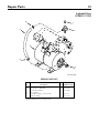
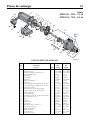
Exploded View
07SJH11C - 3/4 HP
07SJH11C115H - 3/4 HP
10SJH11C - 1 HP
REPAIR PARTS LIST
07SJH11C
Key Part No. 07SJH11C115H 10SJH11C
No. Description Used 3/4 HP 1 HP
1 Motor 1 J218-1006 J218-1007
2 Slinger 1 C69-7 C69-7
3 Seal Plate 1 784S0070 784S0070
4 O-Ring 1 111P0490 111P0490
5A Shaft Seal Seat 1 111P0510 111P0510
5B Shaft Seal Rotating 1 111P0500 111P0500
6 Impeller 1 101P1720 101P1730
7 Venturi 1 101P2900 101P2900
8 O-Ring 1 111P1100 111P1100
9 90° Hose Barb 1 171P4750T 171P4750T
10 Pump Body 1 723S0850 723S0850
11 Plug, Stainless Steel 1 121P2100 121P2100
12 Washer 1 111P0990 111P0990
13 Screw, Socket Head 8 121P0310 121P0310
14 Base 1 C4-42P C4-42P
15 Bolt 2 U30-73SS U30-73SS
16 Pressure Switch Tube 1 U37-677P U37-677P
17 1/4” NPT 90° Hose Barb 1 U111-212T U111-212T
18 Nut 8 U36-207SS U36-207SS
19 Pressure Switch 1 U217-1202 U217-1202
20 1/2” Locknut 1 U36-112ZP U36-112ZP
21 Connector 1 L43-5C L43-5C

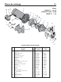
Repair Parts 12
1
1867 0795SR
AVC
Port
2
3
4
5
6
7
8
9
10
11
12
13
14
15
16
17
18
19
20
21
22
23
24
25
14
26
27
28
Exploded View
05PNS11S / 5PN - 1/2 HP
07PNS11S / 7PN - 3/4 HP
REPAIR PARTS LIST
05PNS11S 07PNS11S
Key 5PN 7PN
No. Part Description Qty. 1/2 HP 3/4 HP
1 Motor 1 A100CLL A100DLL
2 Water Slinger 1 17351-0009 17351-0009
3 Seal Plate Assembly (Incl. #5) 1 N103-12PSS N103-12PSS
4 Heat Sink 1 J3-2SS J3-2SS
5 “O” Ring 1 U9-390 U9-390
6 Shaft Seal 1 U109-6A U109-6A
7 Impeller 1 J105-40PF J105-42PTB
8 Rubber Pad 1 C35-41 C35-41
9 Diffuser 1 N1-28P N1-28P
10 Capscrew #10-16 Hex Head 2 U30-738SS U30-738SS
11
Pump Body Assembly (incl. #12 thru #18)
1 N176-35P N176-35PA
12 Pump Body 1 N76-35P N76-35P
13 Pipe Plug 1/8” NPT Taped 1 WC78-41T WC78-41T
14 Comp. Elbow 1/4” NPT w/TFE 2 U111-86T U111-86T
15 Switch Tube 1 U37-670P U37-670P
16 Gasket - Plastic 1 J20-18 J20-18
17 Pump Jet Body Insert 1 N76-29P N76-29P
18 Capscrew #10-16 4 U30-742SS U30-742SS
19 Nozzle 1 N34P-17 N34P-19
20 Venturi 1 N32P-78 N32P-66
21 “O” Ring 1 U9-201 U9-201
22 Base Assembly Painted 1 J104-9F J104-9F
23 Lock Washer 3/8” 4 U43-12ZP U43-12ZP
24 Nut 3/8-16 4 U36-38ZP U36-38ZP
25 Rubber Pad 1 C35-5 C35-5
26 Pressure Switch 1 U217-1216 U217-1216
27 Locknut 1/2” 1 U36-112ZP U36-112ZP
28 Connector 1/2” 1 L43-5C L43-5C

Repair Parts 13
1
2
3
4
6
5
4
3263 0598 WG
Exploded View
07SJH11C115H
REPAIR PARTS LIST
Key Part No.
No. Description Used 07SJH11C115H
1 1/2” NPT Pipe Plug 1 *
2 Discharge Tee with Barb 1 U78-961P
3 1” NPT Street Elbow 1 U78-974P
4 Hose Clamp 1 *
5 1” Reinforced Hose, 24-1/2” Long 1 U74-37V
6 Tank Assembly 1 U231-360
* Standard hardware item, purchase locally.

This page intentionally left blank

Installation/Fonctionnement/Pièces
Pour plus de renseignements concernant l’utilisation, l’installation ou l’entretien,
Composer le 1 (888) 782-7483
293 WRIGHT STREET, DELAVAN, WI 53115 WWW.BERKELEYPUMPS.COM
PH: 888-782-7483
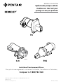
Manual D’uTIlIsaTIon
Systèmes de pompes enfonte
montées sur réservoir pour
puisage en eau peu profonde
© 2013 Pentair, Ltd. All Rights Reserved. BE312 (Rév. 22/02/13)
558 0397
SJH
®
1537 0195
PNS
FN

Sécurité 2
LIRE TOUTES CES INSTRUCTIONS
ET LES SUIVRE!
Ce symbole indique qu'il faut être prudent. Lorsque ce
symbole apparaît sur la pompe ou dans cette Notice,
rechercher une des mises en garde qui suivent, car elles
indiquent un potentiel possible de blessures corporelles :
avertit d'un danger qui causera des blessures
corporelles, la mort ou des dommages matériels importants si
on l'ignore.
avertit d'un danger qui risque de causer des
blessures corporelles, la mort ou des dommages matériels
importants si on l'ignore.
avertit d'un danger qui causera ou qui
risquera de causer des blessures corporelles, la mort ou des
dommages matériels importants si on l'ignore.
Le mot NOTA indique des instructions spéciales et importantes
n'ayant aucun rapport avec les dangers.
Lire attentivement toutes les consignes de sécurité
contenues dans cette Notice ou collées sur la pompe.
Garder les autocollants de sécurité en bon état; les remplacer
s'ils manquent ou s'ils ont été endommagés.
Avertissement lié à la Proposition 65 de la Californie
Ce produit et les accessoires connexes
contiennent des produits chimiques reconnus dans l’État
de la Californie comme pouvant provoquer des cancers,
des anomalies congénitales ou d’autres dangers relatifs à la
reproduction.
SÉCURITÉ CONCERNANT L'ÉLECTRICITÉ
La tension du condensateur peut être
dangereuse. Pour décharger le condensateur du moteur, tenir
un tournevis à manche isolé PAR LE MANCHE et mettre en
court-circuit les bornes du condensateur. Ne pas toucher la
lame métallique du tournevis ni les bornes du condensateur.
En cas de doute, consulter un électricien qualifié.
SÉCURITÉ GÉNÉRALE
Ne pas toucher un moteur qui fonctionne.
Les moteurs modernes sont conçus pour fonctionner par
des températures élevées. Pour ne pas se brûler lorsque l'on
interviendra sur la pompe, la laisser refroidir pendant 20
minutes après l'avoir arrêtée avant de la toucher.
Ne pas laisser geler la pompe ni aucun autre élément du
système, sinon la garantie sera annulée.
Ne pomper que de l'eau avec cette pompe.
Périodiquement, inspecter la pompe et tous les éléments du
système.
Toujours porter des lunettes de sécurité lorsque l'on intervient
sur une pompe.
Garder la zone de travail propre, non encombrée et bien
éclairée; tous les outils et tout l'équipement non utilisés doivent
être entreposés correctement.
Ne pas laisser les visiteurs s'approcher de la zone de travail.
Le corps de la pompe peut exploser si la
pompe est utilisée en tant que pompe de surpression, à moins
qu'une soupape de sûreté pouvant laisser passer le débit
maximum de la pompe à 75 lb/po
2
soit posée.
AVERTISSEMENT
Tension dangereuse. Risque
de secousses électriques, de
brûlures, voire de mort.
Mettre à la terre la pompe
avant de la brancher sur le
courant électrique. Couper
l'arrivée de courant avant d'in-
tervenir sur la pompe, sur le
moteur ou sur le réservoir.
Câbler le moteur en
fonction de la bonne
tension. Voir la
Section «Électricité»
de cette Notice et la
plaque signalétique du
moteur.
Mettre à la terre le
moteur avant de le
brancher sur le
courant électrique.
Conforme au Code
national de
l'électricité, au Code
canadien de
l'électricité et aux
codes municipaux
pour tous les câblages.
Respecter les instructions de câblage figurant
dans cette Notice lorsque l'on branche le moteur
sur une ligne haute tension.
AVERTISSEMENT
Pression dangereuse!
Poser une soupape de sûreté
sur le tuyau de refoulement.
Dissiper toute la pression
du système avant d'intervenir
sur un élément.

Table des matières 3
Merci d'avoir acheté une pompe de qualité supérieure mise à l'essai à l'usine.
Page
Sécurité ........................................................................................................................... 2
Garantie ........................................................................................................................... 3
Installation .................................................................................................................... 4,5
Branchement de la tuyauterie de refoulement ................................................................. 6
Électricité ...................................................................................................................... 7,8
Préparations avant le démarrage de la pompe ................................................................. 8
Diagnostic des pannes ..................................................................................................... 9
Pièces de rechange ................................................................................................... 10-13
Garantie limitée
BERKELEY garantit au consommateur initial (ci-après appelé l’« Acheteur ») que les produits énumérés dans les présentes sont exempts de
défaut de matériau et de fabrication pendant la durée des garanties à compter de la durée des garanties indiquées ci-dessous.
Produits Durée des garanties
Systèmes d’eau :
Produits de systèmes d’eau — Pompes à éjecteur, petites pompes centrifuges, pompes
submersibles et tous les accessoires connexes
Selon le premier terme atteint :
12 mois à compter de la date de la première installation ou
18 mois à compter de la date de fabrication
Réservoirs composites Pro-Sour
ce™ 5 ans à compter de la date de la première installation
Réservoirs sous pression en acier Pro-Source™ 5 ans à compter de la date de la première installation
Réservoirs revêtus d’époxyde Pro-Source™ 3 ans à compter de la date de la première installation
Produits de puisard/d’égout/d’effluents
12 mois à compter de la date de la première installation ou
18 mois à compter de la date de fabrication
Agricole/commercial:
Centrifuges – entr
aînement par moteur monobloc, monté sur cadre, monté sur SAE,
entraînement par moteur à combustion, multiétagé vertical, SSCX, SSHM, pompes
pour les matières solides, pompes submersibles pour les matières solides
12 mois à compter de la date de la première installation ou
24 mois à compter de la date de fabrication
Turbines submersibles, diamètre de 6po et plus gr
and
12 mois à compter de la date de la première installation ou
24 mois à compter de la date de fabrication
Nos garanties limitée ne s’appliquent pas aux produits ayant fait l’objet de négligence, d’une mauvaise utilisation, d’une mauvaise
installation ou d’un manque d’entretien adéquat. Sans aucune limitation des présentes, la garantie des moteurs triphasés submersibles
sera nulle et non avenue si ces moteurs sont branchés et fonctionnent sur le courant monophasé par l’intermédiaire d’un déphaseur. Il faut
également noter que les moteurs triphasés doivent être protégés par un relais de surcharge tripolaire thermocompensé à déclenchement
extrêmement rapide du calibre recommandé, sinon la garantie sera nulle et non avenue.
Le seul recours de l’Acheteur et la seule responsabilité de BERKELEY consistent à réparer ou à remplacer (au choix de BERKELEY) les
produits qui se révéleraient défectueux. L’Acheteur s’engage à payer tous les frais de main d’œuvre et d’expédition du produit couvert par
sa garantie et de s’adresser au concessionnaire-installateur ayant procédé à l’installation dès qu’un problème est découvert pour obtenir
un service sous garantie. Aucune demande de service en vertu de sa garantie ne sera acceptée après expiration de la durée de sa garantie.
Ces garanties ne sont pas transférables.
BERKELEY DÉCLINE TOUTE RESPONSABILITÉ POUR TOUT DOMMAGE INDIRECT OU FORTUIT QUEL QU’IL SOIT.
LA GARANTIE LIMITÉE SUSMENTIONNÉE EST EXCLUSIVE ET REMPLACE TOUTES LES AUTRES GARANTIES EXPRESSES ET TACITES, Y
COMPRIS, MAIS SANS S’Y LIMITER, LES GARANTIES DE QUALITÉ MARCHANDE ET D’ADAPTATION À UN USAGE PARTICULIER. LA
GARANTIE LIMITÉE SUSMENTIONNÉE NE DOIT PAS ÊTRE PROLONGÉE AU-DELÀ DE LA DURÉE PRÉVUE AUX PRÉSENTES.
Certains états, territoires et certaines provinces ne permettent pas l’exclusion ou la limitation des dommages indirects ou fortuits, ni les
limitations relatives à la durée des garanties tacites. Par conséquent, il se peut que les limitations ou les exclusions stipulées dans les
présentes ne s’appliquent pas dans ce cas. Ces garanties accordent des droits juridiques précis, bien que l’on puisse bénéficier d’autres
droits, selon la province, le territoire ou l’état dans lequel on réside.
La présente garantie limitée est entrée en vigueur le 1er juin 2011 et remplace toute garantie non datée ou antérieure à cette date.
Aux États-Unis : BERKELEY, 293 Wright St., Delavan, WI 53115
Au Canada : 269 Trillium Dr., Kitchener, Ontario N2G 4W5

REMPLACEMENT D'UNE ANCIENNE POMPE
Tension dangereuse. Couper l'arrivée de
courant à la pompe avant d'intervenir sur la pompe ou sur
le moteur.
1 ° Vider toute l'eau de l'ancienne pompe; déposer
l'ancienne pompe. Vérifier l'ancienne tuyauterie à la
recherche de dépôts de tartre, de chaux, de rouille,
etc.; la remplacer selon le besoin.
2 ° Brancher la pompe sur le système. S'assurer que tous
les raccords du tuyau d'aspiration sont bien étanches,
aussi bien à l'air qu'à l'eau. Si le tuyau d'aspiration
aspire de l'air, la pompe ne pompera pas l'eau du puits.
3 ° Régler la hauteur de montage de la pompe de façon
que les raccords de plomberie n'exercent aucune
contrainte sur le corps de la pompe. Supporter les
tuyaux de façon que le corps de la pompe ne supporte
pas le poids de la tuyauterie ni des raccords.
Le branchement de cette pompe à éjecteur neuve pour
puits profonds sur la tuyauterie du puits est maintenant
terminé. Passer à la page 6 pour le branchement de la
tuyauterie de refoulement et sur un réservoir.
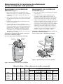
INSTALLATION DE LA POINTE
FILTRANTE
(Figure 1)
1 ° Enfoncer la pointe dans le sol, en utilisant des «raccords
d'enfoncement» et des «chapeaux de battage». Les
«raccords d'enfoncement» sont filetés sur toute leur
longueur, ce qui permet aux extrémités des tuyaux de
venir en butée l'une contre l'autre de façon que la force
d'enfoncement du maillet soit absorbée par le tuyau et
non pas par les filets. Les raccords ordinaires que l'on
trouve dans les quincailleries ne sont pas filetés sur toute
leur longueur et ils risquent de s'écraser sous l'impact
des coups. Les «raccords d'enfoncement» sont également
plus lisses que les raccords de plomberie standard, ce qui
leur permet de pénétrer plus facilement dans le sol.
2 ° Monter la pompe aussi près que possible du puits.
3 ° Utiliser le moins possible de raccords (en particulier
des coudes) lorsque l'on branche la tuyauterie de la
pointe filtrante sur l'orifice d'aspiration de la pompe. Le
diamètre du tuyau d'aspiration doit être au moins aussi
grand que le diamètre de l'orifice d'aspiration de la
pompe (y compris le clapet anti-retour si la pompe n'en
comporte pas un - voir la Figure 1). Supporter le tuyau
de façon qu'il ne soit pas cintré afin qu'il n'exerce pas
de contraintes sur le corps de la pompe; de plus, il doit
être légèrement incliné vers le haut, du puits jusqu'à
la pompe (les points hauts risquent de causer des
poches et des bouchons d'air dans la pompe). Rendre
étanches les joints du tuyau d’aspiration avec du ruban
d’étanchéité en PTFE pour filetage. Les raccords doivent
être étanches à l'air et à l'eau. Si le tuyau d'aspiration
aspire de l'air, la pompe ne pompera pas l'eau du
puits. Si une pointe filtrante ne fournit pas suffisamment
d'eau, considérer brancher deux ou trois pointes
filtrantes sur un même tuyau d'aspiration.
Le branchement de cette pompe à éjecteur neuve pour
puits profonds sur la tuyauterie du puits est maintenant
terminé. Passer à la page 6 branchement pour la tuyauterie
de refoulement et sur un réservoir.
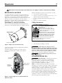
INSTALLATION SUR UN PUITS À
TUBAGE DE 2 POUCES DE DIAMÈTRE OU
PLUS GRAND
(voir la Figure 2)
1 ° Monter la pompe aussi près que possible du puits.
2 ° Brancher le clapet de pied, la crépine et le tuyau du
puits (voir la Figure 2). S'assurer que le clapet de pied
fonctionne librement.
Installation 4
Figure 1: Installation avec une pointe filtrante
Figure 2 : Installation dans un puits à tubage
To Household
Water System
Pump Priming
Tee and Plug
Not
to
Scale
Check
Valve
10'
Min.
5–10'
Suction Pipe
From Well
Priming
Tee and
Plug
Foot
Valve
Sanitary
Well Seal
Well
Casing
2347 0396
Vers le système d'eau
de la maison
Bouchon et té
d’amorçcage
de la pompe
Tuyau d'aspiration
venant du puits
Clapet
anti-retour
Té
d'amorçage
etbouchon
Joint sanitaire
du puits
Tubage
du puits
Pas à
l'échelle
5 à 10 pi
Au moins
10 pi
Clapet
de pied
To Household
Water System
Not
to
Scale
Pump Priming
Tee and Plug
Suction Pipe
From Well
Drive
Coupling
Drive
Point
Check
Valve
Priming
Tee and
Plug
Drive point
below water
level
2346 0396
Vers le système d'eau
de la maison
Bouchon et té
d’amorçcage
de la pompe
Té
d'amorçage
et bouchon
Clapet
anti-retour
Pointe filtrante
sous le niveau
de l’eau.
Pointe
filtrante
Pas à
l'échelle
Tuyau d'aspiration
venant du puits
Raccord
d'enfoncement de la
pointe filtrante

3 ° Abaisser le tuyau dans le puits jusqu'à ce que la crépine
soit à cinq pieds du fond du puits. Pour que la pompe
n'aspire pas d'air, la crépine doit être au moins à 10
pieds sous le niveau de l'eau du puits pendant que la
pompe fonctionne. Poser un joint sanitaire de puits.
4 ° Poser le té d'amorçage, le bouchon d'amorçage et
le tuyau d'aspiration sur la pompe (voir la Figure 2).
Brancher le tuyau provenant du puits sur l'orifice
d'aspiration de la pompe en utilisant le moins possible
de raccords - en particulier des coudes - étant donné
que les raccords augmentent le frottement de l'eau
dans les tuyaux (il faut toutefois ajouter un clapet
de pied — voir la Figure 2). Le diamètre du tuyau
d'aspiration doit être au moins aussi grand que le
diamètre de l'orifice d'aspiration de la pompe. Utiliser
du ruban d’étanchéité en PTFE pour filetage sur les
raccords de tuyaux filetés. Supporter le tuyau de
façon qu'il ne soit pas cintré afin qu'il n'exerce pas de
contraintes sur le corps de la pompe; de plus, il doit
être légèrement incliné vers le haut, du puits jusqu'à
la pompe (les points hauts risquent de causer des
poches et des bouchons d'air dans la pompe). Rendre
étanches les joints du tuyau d’aspiration avec du
ruban d’étanchéité en PTFE pour filetage. Les raccords
doivent être étanches à l'air et à l'eau. Si le tuyau
d'aspiration aspire de l'air, la pompe ne pompera pas
l'eau du puits.
Le branchement de cette pompe à éjecteur neuve pour
puits profonds sur la tuyauterie du puits est maintenant
terminé. Passer à la page 15 pour le branchement de la
tuyauterie de refoulement et sur un réservoir.
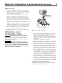
INSTALLATION DANS LE CAS D'EAUX EN
SURFACE
(Figure 3)
1 ° Monter la pompe aussi près que possible du puits en
utilisant le moins possible de raccords (en particulier
des coudes) sur le tuyau d'aspiration. Le diamètre du
tuyau d'aspiration doit être au moins aussi grand que le
diamètre de l'orifice d'aspiration de la pompe.
2 ° Assembler le clapet de pied et le tuyau d'aspiration
(voir la Figure 3). S'assurer que le clapet de pied
fonctionne librement. Utiliser du ruban d’étanchéité
en PTFE pour filetage sur les raccords de tuyaux filetés.
Poser une crépine autour du clapet de pied pour le
protéger contre les poissons, les déchets, etc. (voir la
Figure 3).
3 ° Abaisser le tuyau dans le puits jusqu'à ce que la
crépine soit à cinq pieds du fond du puits. Pour que la
pompe n'aspire pas d'air, la crépine doit être au moins
à 10 pieds sous le niveau de l'eau du puits pendant
que la pompe fonctionne.
4 ° Poser le té d'amorçage, le bouchon d'amorçage et
le tuyau d'aspiration sur la pompe (voir la Figure 3).
Supporter le tuyau de façon qu'il ne soit pas cintré
afin qu'il n'exerce pas de contraintes sur le corps de
la pompe; de plus, il doit être légèrement incliné vers
le haut, du puits jusqu'à la pompe (les points hauts
risquent de causer des poches et des bouchons d'air
dans la pompe). Rendre étanches les joints du tuyau
d’aspiration avec du ruban d’étanchéité en PTFE pour
filetage. Les raccords doivent être étanches à l'air et à
l'eau. Si le tuyau d'aspiration aspire de l'air, la pompe
ne pompera pas l'eau du puits.
Le branchement de cette pompe à éjecteur neuve pour
puits profonds sur la tuyauterie du puits est maintenant
terminé. Passer à la page 6 pour le branchement de la
tuyauterie de refoulement et sur un réservoir.
Installation 5
Figure 3 : Installation pour les eaux de surface
To Household
Water System
Pump Priming
Tee and Plug
Check
Valve
Not
to
Scale
Suction Pipe
From Well
10'
Min.
5–10'
Foot
Valve
Screen
Priming
Tee and
Plug
2348 0396
Vers le système d'eau
de la maison
Bouchon et té
d’amorçcage
de la pompe
Tuyau d'aspiration
venant du puits
Clapet
anti-retour
Bouchon
et té
d’amorçcage
de la pompe
Pas à
l'échelle
Au moins
10 pied
Clapet de
pied
5 à 10 pi
Crépine
Étanchéité des raccords des tuyaux
Effectuer tous les raccordements filetés à la pompe
seulement avec du ruban d’étanchéité en PTFE pour
filetage. S'assurer que tous les raccords du tuyau d'as-
piration sont bien étanches, aussi bien à l'air qu'à
l'eau. Si le tuyau d'aspiration aspire de l'air, la pompe
ne pompera pas l'eau du puits.

Branchement de la tuyauterie de refoulement
et sur un réservoir sous pression 6
BRANCHEMENT SUR UN RÉSERVOIR
PRÉCHARGÉ
(Figure 4)
1 ° Poser deux tés dans l'orifice de refoulement de la
pompe (voir la Figure 4). Le diamètre du tuyau doit être
au moins aussi grand que le diamètre de l'orifice de
refoulement.
2 ° Poser un tuyau rigide ou un tuyau souple renforcé entre
une des branches du premier té et l'orifice du réservoir
préchargé.
3 ° Brancher l'autre extrémité du té de refoulement sur le
système de la plomberie.
4 ° Vérifier la précharge d'air dans le réservoir avec un
manomètre pour pneu. La précharge doit être de 2 lb/po
2
inférieure au réglage de la pression d'enclenchement du
manocontacteur de la pompe. La précharge se mesure
lorsqu'il n'y a pas de pression d'eau dans le réservoir.
Cette pompe neuve est équipée d'un manocontacteur
30/50 lb/po
2
; la pression de précharge du réservoir devra
donc être réglée à 28 lb/po
2
.
Félicitations! Le branchement de la pompe à éjecteur sur
le réservoir est maintenant terminé.
Passer aux page 7 pour les branchements électriques.
BRANCHEMENT SUR UN RÉSERVOIR
STANDARD
(Figure 5)
1 ° Poser un té dans l'orifice de refoulement de la pompe
(voir la Figure 5).
2 ° Poser un tuyau entre l'orifice de refoulement de
la pompe et l'orifice d'admission du réservoir. Le
diamètre du tuyau doit être au moins aussi grand que
le diamètre de l'orifice de refoulement de la pompe.
3 ° Déposer le bouchon fileté de 1/8 de pouce NPT de
l'orifice du contrôleur d'air de la pompe (voir la Figure
5). Poser un tube entre l'orifice du contrôleur d'air
(voir la Figure 5) de la pompe et l'orifice du contrôleur
d'air monté sur le réservoir. Pour plus de détails, se
reporter aux instructions fournies avec le réservoir
et le contrôleur d'air. L'emplacement de l'orifice du
contrôleur d'air variera en fonction du modèle de
pompe (se reporter aux vues éclatées, page 9).
Félicitations! Le branchement de la pompe à éjecteur sur
le réservoir est maintenant terminé.
Passer aux page 7 pour les branchements électriques.
Tableau de câblage – Câbles et diamètres des fusibles recommandés
DISTANCE EN PIEDS (MÈTRES) ENTRE LE MOTEUR
Fusible
ET LE COURANT D’ALIMENTATION
Charge
intensité
0 - 100 101 - 200 201 - 300 301 - 400 401 - 500
max. en
en
(0 - 30) (31 - 61) (62 - 91) (92 - 122) (123 - 152)
Modèle ch Tension ampères ampères
DIAMÈTRE DU FIL – CALIBRE AWG (mm
2
)
5FN-L 1/2 115/230 9,4/4,7 15/15 14/14(2/2) 10/14(5,5/2) 10/14(5,5/2) 6/14(14/2) 6/12(14/3)
7FN-L 3/4 115/230 12,4/6,2 20/15 12/14(3/2) 10/14(5,5/2) 8/14(8,4/2) 6/12(14/3) 6/12(14/3)
5PN, 05PNS11S 1/2 115/230 9,4/4,7 15/15 14/14(2/2) 10/14(5,5/2) 10/14(5,5/2) 6/14(14/2) 6/12(14/3)
7PN, 07PNS11S 3/4 115/230 12,2/6,1 20/15 12/14(3/2) 10/14(5,5/2) 8/14(8,4/2) 6/12(14/3) 6/12(14/3)
07SJH11C 3/4 115/230 14,8/7,4 20/15 12/14(3/2) 8/14(8,4/2) 6/14(14/2) 6/12(4/3) 4/10(21/5,5)
10SJH11C 1 115/230 19,2/9,6 25/15 10/14(5,5/2) 8/14(8,4/2) 6/12(14/3) 4/10(21/5,5) 4/10(21/5,5)
Figure 4 : Branchements sur un réservoir préchargé
From Well
Pressure
Switch
To Household
Water System
Pump Priming
Tee and Plug
Check
Valve
2349 0396
Vers le système
d'eau de la maison
Bouchon et tée
d’amorçage
de la pompe
En provenance
du puits
Manocontacteur
Clapet
anti-retour
Figure 5 : Branchements sur un réservoir standard
To Household
Water System
From
Well
Air Volume
Control
Air Volume
Control Tube
Pump
Priming Te e
and Plug
Pressure
Switch
2350 0396
Check
Valve
Clapet
anti-retour
Vers le système
d'eau de la maison
Contrôleur
d'air
Tube du
contrôleur d'air
Té d'amorçage
et bouchon
Manocontacteur
En provenance
du puits
Page is loading ...
Page is loading ...
Page is loading ...
Page is loading ...
Page is loading ...
Page is loading ...
Page is loading ...
Page is loading ...
-
 1
1
-
 2
2
-
 3
3
-
 4
4
-
 5
5
-
 6
6
-
 7
7
-
 8
8
-
 9
9
-
 10
10
-
 11
11
-
 12
12
-
 13
13
-
 14
14
-
 15
15
-
 16
16
-
 17
17
-
 18
18
-
 19
19
-
 20
20
-
 21
21
-
 22
22
-
 23
23
-
 24
24
-
 25
25
-
 26
26
-
 27
27
-
 28
28


Berkeley FN, SJH, PNS Shallow Well Jet Pumps/Tank Systems Owner's manual
- Category
- Water pumps
- Type
- Owner's manual
Ask a question and I''ll find the answer in the document
Finding information in a document is now easier with AI
in other languages
Related papers
-
Berkeley 5PNP15H Shallow Well Water System Owner's manual
-
-
-
Pentair BPD Series Corrosion Resistant Self-Priming Centrifugal Pump Owner's manual
-
-
-
-
-
-
Other documents
-
STA-RITE SN / HN Series Owner's manual
-
Flotec FP401215H User guide
-
Wayne Jet Pump Water Systems Shallow Well Owner's manual
-
-
MYERS MPN, MFN Series Owner's manual
-
-
Simer 2803 User manual
-
-
Flotec FP4105 Owner's manual
-