MSI MS-7721v6.0 Owner's manual
- Category
- Motherboards
- Type
- Owner's manual
This manual is also suitable for

Preface
Copyright Notice
The material in this document is the intellectual property of MICRO-STAR
INTERNATIONAL. We take every care in the preparation of this document, but no
guarantee is given as to the correctness of its contents. Our products are under
continual improvement and we reserve the right to make changes without notice.
Trademarks
All trademarks in this manual are properties of their respective owners.
MSI
®
is registered trademark of Micro-Star Int’l Co.,Ltd.
NVIDIA
®
is registered trademark of NVIDIA Corporation.
ATI
®
is registered trademark of AMD Corporation.
AMD
®
is registered trademarks of AMD Corporation.
Intel
®
is registered trademarks of Intel Corporation.
Windows
®
is registered trademarks of Microsoft Corporation.
AMI
®
is registered trademark of American Megatrends Inc.
Award
®
is a registered trademark of Phoenix Technologies Ltd.
Sound Blaster
®
is registered trademark of Creative Technology Ltd.
Realtek
®
is registered trademark of Realtek Semiconductor Corporation.
JMicron
®
is registered trademark of JMicron Technology Corporation.
Netware
®
is registered trademark of Novell, Inc.
Lucid
®
is trademark of LucidLogix Technologies, Ltd.
VIA
®
is registered trademark of VIA Technologies, Inc.
ASMedia
®
is registered trademark of ASMedia Technology Inc.
iPad, iPhone, and iPod are trademarks of Apple Inc.
Qualcomm Atheros and Killer are trademarks of Qualcomm Atheros Inc.
Revision History
Revision Revision History Date
V6.
Add A58M-E35 204/ 02
V6.2 Add A88XM-P33 204/ 04
■
■
■
■
■
■
■
■
■
■
■
■
■
■
■
■
■
G52-77203

Preface
2
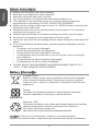
Safety Instructions
Always read the safety instructions carefully.
Keep this User’s Manual for future reference.
Keep this equipment away from humidity.
Lay this equipment on a reliable at surface before setting it up.
The openings on the enclosure are for air convection hence protects the
equipment from overheating. DO NOT COVER THE OPENINGS.
Make sure the voltage of the power source is at 0/220V before connecting the
equipment to the power inlet.
Place the power cord such a way that people can not step on it. Do not place
anything over the power cord.
Always Unplug the Power Cord before inserting any add-on card or module.
All cautions and warnings on the equipment should be noted.
Never pour any liquid into the opening that can cause damage or cause electrical
shock.
If any of the following situations arises, get the equipment checked by service
personnel:
The power cord or plug is damaged.
Liquid has penetrated into the equipment.
The equipment has been exposed to moisture.
The equipment does not work well or you can not get it work according to
User’s Manual.
The equipment has been dropped and damaged.
The equipment has obvious sign of breakage.
DO NOT LEAVE THIS EQUIPMENT IN AN ENVIRONMENT ABOVE 60
o
C
(40
o
F), IT MAY DAMAGE THE EQUIPMENT.
■
■
■
■
■
■
■
■
■
■
■
◯
◯
◯
◯
◯
◯
■
California, USA:
The button cell battery may contain perchlorate material and requires
special handling when recycled or disposed of in California.
For further information please visit:
http://www.dtsc.ca.gov/hazardouswaste/perchlorate/
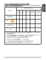
Taiwan:
For better environmental protection, waste batteries should be
collected separately for recycling or special disposal.
廢電池請回收
European Union:
Batteries, battery packs, and accumulators should not be disposed
of as unsorted household waste. Please use the public collection
system to return, recycle, or treat them in compliance with the local
regulations.
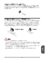
Battery Information
CAUTION: There is a risk of explosion, if battery is incorrectly replaced.
Replace only with the same or equivalent type recommended by the manufacturer.

Preface
3
FCC-B Radio Frequency Interference Statement
This equipment has been tested and found to comply with the limits for a Class
B digital device, pursuant to Part 5 of the FCC Rules. These limits are designed
to provide reasonable protection against harmful interference in a residential
installation. This equipment generates, uses and can radiate radio frequency
energy and, if not installed and used in accordance with the instructions, may cause
harmful interference to radio communications. However, there is no guarantee that
interference will not occur in a particular installation. If this equipment does cause
harmful interference to radio or television reception, which can be determined
by turning the equipment o and on, the user is encouraged to try to correct the
interference by one or more of the measures listed below.
Reorient or relocate the receiving antenna.
Increase the separation between the equipment and receiver.
Connect the equipment into an outlet on a circuit dierent from that to which
the receiver is connected.
Consult the dealer or an experienced radio/television technician for help.
Notice
The changes or modications not expressly approved by the party responsible for
compliance could void the user’s authority to operate the equipment.
Notice 2
Shielded interface cables and A.C. power cord, if any, must be used in order to
comply with the emission limits.
VOIR LA NOTICE D’INSTALLATION AVANT DE RACCORDER AU RESEAU.
Micro-Star International
MS-772
This device complies with Part 5 of the FCC Rules. Operation is subject to the
following two conditions:
this device may not cause harmful interference, and
this device must accept any interference received, including interference that
may cause undesired operation.
CE Conformity
Hereby, Micro-Star International CO., LTD declares that this device is
in compliance with the essential safety requirements and other relevant
provisions set out in the European Directive.
◯
◯
◯
◯
)
2)

Preface
4
Radiation Exposure Statement
This equipment complies with FCC radiation exposure limits set forth for an
uncontrolled environment. This equipment and its antenna should be installed and
operated with minimum distance 20 cm between the radiator and your body. This
equipment and its antenna must not be co-located or operating in conjunction with
any other antenna or transmitter.
European Community Compliance Statement
The equipment complies with the RF Exposure Requirement 999/59/EC, Council
Recommendation of 2 July 999 on the limitation of exposure of the general public
to electromagnetic elds (0–300GHz). This wireless device complies with the R&TTE
Directive.
Taiwan Wireless Statements
無線設備警告聲明
經型式認證合格之低功率射頻電機,非經許可,公司、商號或使用者均不得擅自變更
頻率、加大功率或變更原設計之特性及功能。
低功率射頻電機之使用不得影響飛航安全及干擾合法通信;經發現有干擾現象時,應
立即停用,並改善至無干擾時方得繼續使用。前項合法通信,指依電信法規定作業之
無線電通信。低功率射頻電機須忍受合法通信或工業、科學及醫療用電波輻射性電機
設備之干擾。
警告使用者:這是甲類資訊產品,在居住的環境中使用時,可能會造成無線電干擾,在
這種情況下,使用者會被要求採取某些適當的對策。
Japan VCCI Class B Statement
クラス B 情報技術装置
この装置は、情報技術装置等電波障害自主規制協議会(VCCI)の基準に基づくクラ
スB情報技術装置です。この装置が家庭内でラジオやテレビジョン受信機に近接して
使われると、受信障害を引き起こすことがあります。取扱説明書にしたがって正し
い取り扱いをしてください。
Korea Warning Statements
당해 무선설비는 운용중 전파혼신 가능성이 있음
Chemical Substances Information
In compliance with chemical substances regulations, such as the EU REACH
Regulation (Regulation EC No. 907/2006 of the European Parliament and the
Council), MSI provides the information of chemical substances in products at:
http://www.msi.com/html/popup/csr/evmtprtt_pcm.html
Page is loading ...

Preface
6
WEEE Statement
WEEE (Waste Electrical and Electronic Equipment)
ENGLISH
To protect the global environment and as an environmentalist, MSI must
remind you that...
Under the European Union (“EU”) Directive on Waste Electrical and
Electronic Equipment, Directive 2002/96/EC, which takes eect on August 3, 2005,
products of “electrical and electronic equipment” cannot be discarded as municipal
wastes anymore, and manufacturers of covered electronic equipment will be
obligated to take back such products at the end of their useful life. MSI will comply
with the product take back requirements at the end of life of MSI-branded products
that are sold into the EU. You can return these products to local collection points.
DEUTSCH
Hinweis von MSI zur Erhaltung und Schutz unserer Umwelt
Gemäß der Richtlinie 2002/96/EG über Elektro- und Elektronik-Altgeräte dürfen
Elektro- und Elektronik-Altgeräte nicht mehr als kommunale Abfälle entsorgt werden.
MSI hat europaweit verschiedene Sammel- und Recyclingunternehmen beauftragt,
die in die Europäische Union in Verkehr gebrachten Produkte, am Ende seines
Lebenszyklus zurückzunehmen. Bitte entsorgen Sie dieses Produkt zum gegebenen
Zeitpunkt ausschliesslich an einer lokalen Altgerätesammelstelle in Ihrer Nähe.
FRANÇAIS
En tant qu’écologiste et an de protéger l’environnement, MSI tient à rappeler ceci...
Au sujet de la directive européenne (EU) relative aux déchets des équipement
électriques et électroniques, directive 2002/96/EC, prenant eet le 3 août 2005,
que les produits électriques et électroniques ne peuvent être déposés dans les
décharges ou tout simplement mis à la poubelle. Les fabricants de ces équipements
seront obligés de récupérer certains produits en n de vie. MSI prendra en compte
cette exigence relative au retour des produits en n de vie au sein de la communauté
européenne. Par conséquent vous pouvez retourner localement ces matériels dans
les points de collecte.
РУССКИЙ
Компания MSI предпринимает активные действия по защите окружающей
среды, поэтому напоминаем вам, что....
В соответствии с директивой Европейского Союза (ЕС) по предотвращению
загрязнения окружающей среды использованным электрическим и электронным
оборудованием (директива WEEE 2002/96/EC), вступающей в силу 3
августа 2005 года, изделия, относящиеся к электрическому и электронному
оборудованию, не могут рассматриваться как бытовой мусор, поэтому
производители вышеперечисленного электронного оборудования обязаны
принимать его для переработки по окончании срока службы. MSI обязуется
соблюдать требования по приему продукции, проданной под маркой MSI на
территории EC, в переработку по окончании срока службы. Вы можете вернуть
эти изделия в специализированные пункты приема.
Page is loading ...
Page is loading ...
Page is loading ...
Page is loading ...

English
English
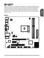
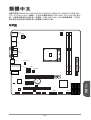
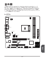
Thank you for choosing the A88XM-E35/ A88XM-P33/ A78M-E35/ A55M-E35/ A58M-
E35 Series (MS-772 v6.X) Micro-ATX motherboards. The A88XM-E35/ A88XM-P33/
A78M-E35/ A55M-E35/ A58M-E35 Series motherboards are based on AMD A88X/
A78/ A55/ A58 chipset for optimal system eciency. Designed to t the advanced
AMD FM2+/ FM2 processor, the A88XM-E35/ A88XM-P33/ A78M-E35/ A55M-E35/
A58M-E35 Series motherboards deliver a high performance and professional desktop
platform solution.
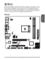
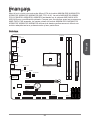
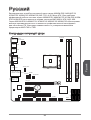
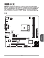
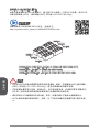
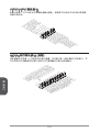
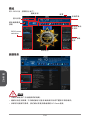
Layout
BAT1
T:Line-I n
M:Line - Ou t
B:MIC- In t
Top: LAN Jac k
Bottom : US B3 .0 ports
Top : mouse po rt
Bottom : ke yb oard port
JAUD1
JBAT1
JCI1
JUSB_P W1
JUSB_P W2
PCI_E1
PCI_E2
PCI1
JUSB2
JUSB1
JUSB3
JFP1
JFP2
SA
TA
3
SA
TA
6
SA
TA
2
SA
TA
5
SA
TA
1
SA
TA
4
SYSF
AN
1
SYSFAN2
CPUFAN
JPWR2
JPWR1
JTPM1
JCOM1
DIMM1
DIMM2
USB2.0 p or ts
USB2.0 p or ts
HDMI por t
JLPT1
Top: VGA Port
Bottom: DV PortI-D

English
2
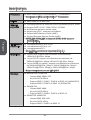
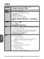
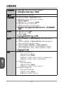
Motherboard Specications
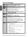
CPU
Support
AMD Socket FM2+ A-Series/Athlon™ Processors*
* Also support FM2 A-Series/Athlon™ Processors
■
Chipset AMD A88X/ A78/ A55/ A58■
Memory
Support
2x DDR3 memory slots supporting up to 32GB
Supports DDR3 233*/ 866/ 600/ 333 MHz
Dual channel memory architecture
Supports non-ECC, un-buered memory
Supports AMD Memory Prole (AMP)
Supports Extreme Memory Prole (XMP)
* A55M-E35/ A58M-E35 do not support DDR3 233 nativity, but
supports it when overclocking.
■
■
■
■
■
■
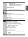
Expansion
Slots
x PCIe 3.0 x6 slot*
x PCIe 2.0 x slot
x PCI slot
* Only FM2+ processors can support PCIe 3.0
■
■
■
Graphics x VGA port, supporting a maximum resolution of 920x200
@ 60Hz, 24bpp
x DVI-D port, supporting a maximum resolution of
2560x600@60Hz, 24bpp/ 920x200 @ 60Hz, 24bpp
x HDMI port (optional), supporting a maximum resolution
of 4096x260@24Hz, 36bpp*/ 3840x260@30Hz, 36bpp*/
920x200@20Hz, 36bpp and 920x200@60Hz, 36bpp
* Only support when using an FM2+ APU
■
■
■
Storage A88XM-E35/ A78M-E35
AMD A88X/ A78 Chipset
6x SATA 6Gb/s ports
Supports RAID 0, RAID, RAID 5 and RAID 0 (A88XM-
E35)
Supports RAID 0, RAID and RAID 0 (A78M-E35)
A88XM-P33
AMD A88X Chipset
4x SATA 6Gb/s ports
Supports RAID 0, RAID, RAID 5 and RAID 0
A55M-E35/ A58M-E35
AMD A55/ A58 Chipset
6x SATA 3Gb/s ports
Supports RAID 0, RAID and RAID 0
■
-
-
-
-
■
-
-
-
■
-
-
-

English
3
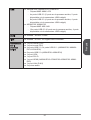
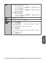
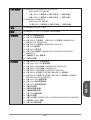
USB A88XM-E35/ A88XM-P33/ A78M-E35
AMD A88X/ A78 Chipset
4x USB 3.0 ports (2 ports on the back panel, 2 ports
available through the internal USB connectors)
8x USB 2.0 ports (4 ports on the back panel, 4 ports
available through the internal USB connectors)
A55M-E35/ A58M-E35
AMD A55/ A58 Chipset
0x USB 2.0 ports (6 ports on the back panel, 4 ports
available through the internal USB connectors)
■
-
-
-
■
-
-
Audio Realtek
®
ALC887 Codec■
LAN Realtek
®
RTL8G Gigabit LAN controller■
Back Panel
Connectors
x PS/2 keyboard port
x PS/2 mouse port
4x USB 2.0 ports, 2x USB 3.0 ports (A88XM-E35/ A88XM-P33/
A78M-E35)
6x USB 2.0 ports (A55M-E35/ A58M-E35)
x VGA port
x DVI-D port
x HDMI port (A88XM-E35/ A78M-E35/ A55M-E35/ A58M-E35)
x LAN (RJ45) port
3x audio jacks
■
■
■
■
■
■
■
■
■
Internal
Connectors
x 24-pin ATX main power connector
x 4-pin ATX 2V power connector
6x SATA 6Gb/s connectors (A88XM-E35/ A78M-E35)
4x SATA 6Gb/s connectors (A88XM-P33)
6x SATA 3Gb/s connectors (A55M-E35/ A58M-E35)
2x USB 2.0 connectors (supports additional 4 USB 2.0 ports)
x USB 3.0 connector (supports additional 2 USB 3.0 ports)
(A88XM-E35/ A88XM-P33/ A78M-E35)
x 4-pin CPU fan connector
x 4-pin system fan connector
x 3-pin system fan connector
x Front panel audio connector
2x System panel connectors
x Chassis Intrusion connector
x TPM module connector
x Serial port connector
x Parallel port connector (A88XM-E35/ A78M-E35/ A55M-E35/
A58M-E35)
x Clear CMOS jumper
2x USB power jumpers
■
■
■
■
■
■
■
■
■
■
■
■
■
■
■
■
■
■

English
4
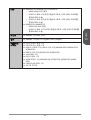
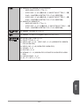
BIOS
Features
64 Mb ash
UEFI AMI BIOS
ACPI 5.0, PnP .0a, SM BIOS 2.7, DMI 2.0
Multi-language
■
■
■
■
Form Factor Micro-ATX Form Factor
8.9 in. x 8.5 in. (22.6 cm x 2.6 cm)
■
■
For the latest information about CPU, please visit http://www.
msi.com/cpu-support/
For more information on compatible components, please
visit http://www.msi.com/test-report/

English
5
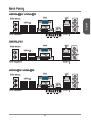
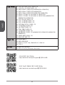
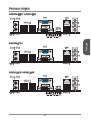
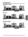
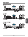
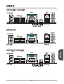
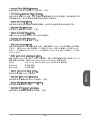
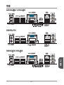
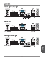
Back Panel
PS/2 Mouse
PS/2 Keyboard USB 3.0
USB 2.0
VGA
LAN
Line-In
DVI-D
HDMI
®
Line-Out
Mic
A88XM-E35/ A78M-E35
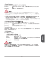
PS/2 Mouse
PS/2 Keyboard USB 2.0
USB 2.0
VGA
LAN
Line-In
DVI-D
HDMI
®
Line-Out
Mic
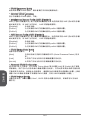
A55M-E35/ A58M-E35
PS/2 Mouse
PS/2 Keyboard USB 3.0
USB 2.0
VGA
LAN
Line-In
DVI-D
Line-Out
Mic
A88XM-P33

English
6
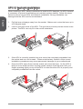
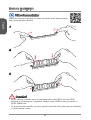
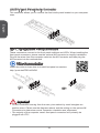
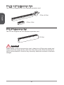
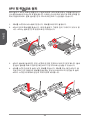
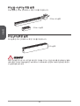
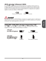
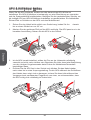
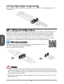
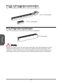
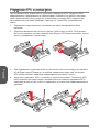
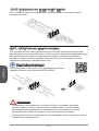
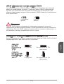
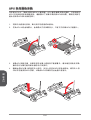
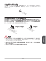
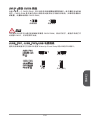
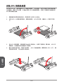
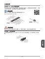
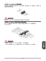
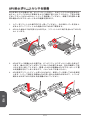
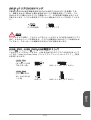
APU & Heatsink Installation
When installing a APU, always remember to install a APU heatsink. An APU heatsink
is necessary to prevent overheating and maintain system stability. Follow the steps
below to ensure correct APU and heatsink installation. Wrong installation can
damage both the APU and the motherboard.
. Pull the lever sideways away from the socket. Make sure to raise the lever up to
a 90-degree angle.
2. Look for the gold arrow of the APU. The gold arrow should point as shown in the
picture. The APU can only t in the correct orientation.
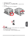
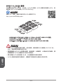
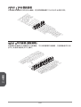
3. If the APU is correctly installed, the pins should be completely embedded into
the socket and can not be seen. Please note that any violation of the correct
installation procedures may cause permanent damages to your motherboard.
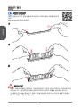
4. Press the APU down rmly into the socket and close the lever. As the APU is
likely to move while the lever is being closed, always close the lever with your
ngers pressing tightly on top of the APU to make sure the APU is properly and
completely embedded into the socket.

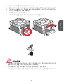
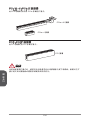
English
7
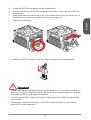
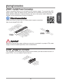
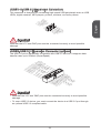
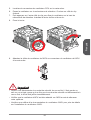
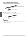
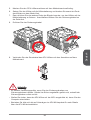
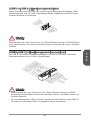
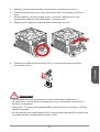
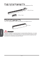
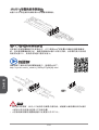
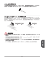
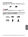
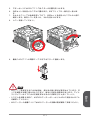
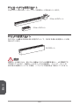
5. Locate the CPU fan connector on the motherboard.
6. Position the cooling set onto the retention mechanism. Hook one end of the clip
to hook rst.
7. Then press down the other end of the clip to fasten the cooling set on the top of
the retention mechanism. Locate the Fix Lever and lift up it.
8. Fasten down the lever.
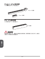
9. Attach the APU Fan cable to the APU fan connector on the motherboard.
Important
While disconnecting the Safety Hook from the xed bolt, it is necessary to keep an
eye on your ngers, because once the Safety Hook is disconnected from the xed
bolt, the xed lever will spring back instantly.
Conrm that the APU cooler has formed a tight seal with the APU before booting
your system.
Please refer to the documentation in the APU cooler package for more details
about APU cooler installation.
•
•
•

English
8
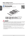
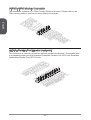
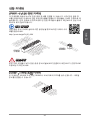
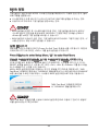
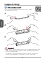
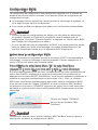
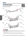
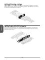
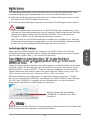
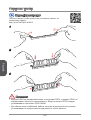
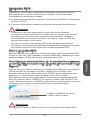
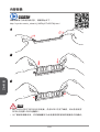
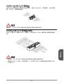
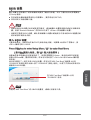
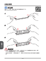
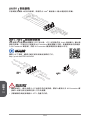
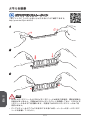
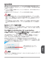
Memory Installation
Video Demonstration
Watch the video to learn how to install memories at the address below.
http://youtu.be/76yLtJaKlCQ
2
3
Important
DDR3 memory modules are not interchangeable with DDR2, and the DDR3
standard is not backward compatible. Always install DDR3 memory modules in
DDR3 DIMM slots.
To ensure system stability, memory modules must be of the same type and density
in Dual-Channel mode.
•
•

English
9
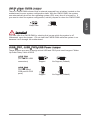
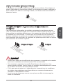
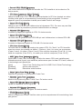
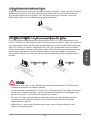
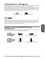
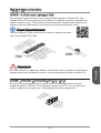
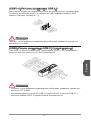
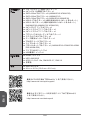
Internal Connectors
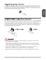
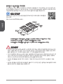
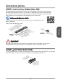
JPWR~2: ATX Power Connectors
These connectors allow you to connect an ATX power supply. To connect the ATX
power supply, align the power supply cable with the connector and rmly press the
cable into the connector. If done correctly, the clip on the power cable should be
hooked on the motherboard’s power connector.
Video Demonstration
Watch the video to learn how to install power supply connectors.
http://youtu.be/gkDYyR_83I4
13.+3. 3
V
1.+3.3
V
14.-12 V
2.+3.3
V
15.Gro und
3
.Groun d
16.PS- ON
#
4.+5
V
17.Gro und
5
.Groun d
18.Gro und
6.+5
V
19.Gro und
7
.Groun d
22.+5
V
10.+12 V
20.Res
8.PW
R O
K
23.+5
V
11
.+12V
21.+5
V
9.5VSB
24.Gro und
12.+3. 3
V
JPWR
4.+12V
2
.Ground
3.+12V
1
.Ground
JPWR2
Important
Make sure that all the power cables are securely connected to a proper ATX power
supply to ensure stable operation of the motherboard.
JCOM: Serial Port Connector
This connector is a 6550A high speed communication port that sends/receives 6
bytes FIFOs. You can attach a serial device.
1
.
D
C
D
3
.
S
O
U
T
1
0
.
N
o
P
i
n
5
.
G
r
o
u
n
d
7
.
R
T
S
9
.
R
I
8
.
C
T
S
6
.
D
S
R
4
.
D
T
R
2
.
S
I
N

English
20
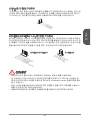
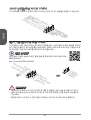
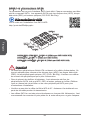
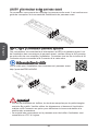
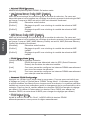
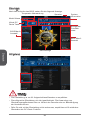
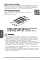
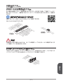
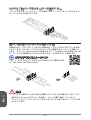
SATA~6: SATA Connectors
This connector is a high-speed SATA interface port. Each connector can connect to
one SATA device. SATA devices include disk drives (HDD), solid state drives (SSD),
and optical drives (CD/ DVD/ Blu-Ray).
Video Demonstration
Watch the video to learn how to Install SATA HDD.
http://youtu.be/RZsMpqxythc
A88XM-E35/ A78M-E35 - SATA~6 (6Gb/s by AMD A88X/ A78)
A88XM-P33 - SATA~4 (6Gb/s by AMD A88X)
A55M-E35/ A58M-E35 - SATA~6 (3Gb/s by AMD A55/ A58)
SATA2
SATA
SATA3
SATA5
SATA4
SATA6
Important
Many SATA devices also need a power cable from the power supply. Such devices
include disk drives (HDD), solid state drives (SSD), and optical drives (CD / DVD /
Blu-Ray). Please refer to the device’s manual for further information.
Many computer cases also require that large SATA devices, such as HDDs, SSDs,
and optical drives, be screwed down into the case. Refer to the manual that came
with your computer case or your SATA device for further installation instructions.
Please do not fold the SATA cable at a 90-degree angle. Data loss may result
during transmission otherwise.
SATA cables have identical plugs on either sides of the cable. However, it is
recommended that the at connector be connected to the motherboard for space
saving purposes.
•
•
•
•

English
2
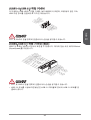
JCI: Chassis Intrusion Connector
This connector connects to the chassis intrusion switch cable. If the computer case
is opened, the chassis intrusion mechanism will be activated. The system will record
this intrusion and a warning message will ash on screen. To clear the warning, you
must enter the BIOS setup and clear the record.
2
.
C
I
N
T
R
U
1
.
G
r
o
u
n
d
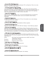
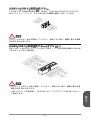
CPUFAN,SYSFAN~2: Fan Power Connectors
The fan power connectors support system cooling fans with +2V. If the motherboard
has a System Hardware Monitor chipset on-board, you must use a specially designed
fan with a speed sensor to take advantage of the CPU fan control. Remember to
connect all system fans. Some system fans may not connect to the motherboard and
will instead connect to the power supply directly. A system fan can be plugged into
any available system fan connector.
1
.Ground
2.+12V
3.Sens
e
4.Speed
C
ontro
l
1
.Gr ound
2.+ 12V
3.N o
Us
e
CPUFAN/ SYSFAN SYSFAN2
Important
Please refer to your processor’s ocial website or consult your vendor to nd
recommended CPU heatsink.
These connectors support Smart Fan Control with liner mode. The Command
Center utility can be installed to automatically control the fan speeds according to
the CPU’s and system’s temperature.
If there are not enough ports on the motherboard to connect all system fans,
adapters are available to connect a fan directly to a power supply.
Before rst boot up, ensure that there are no cables impeding any fan blades.
•
•
•
•

English
22
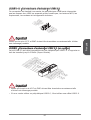
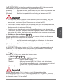
JAUD: Front Panel Audio Connector
This connector allows you to connect the front audio panel located on your computer
case.
1.MI
C L
3.MI
C R
10.Head
P
hone
Detection
5.Head
P
hone
R
7.SENSE_SEN
D
9.Head
P
hone
L
8.No
Pi
n
6.MI
C D
etection
4.NC
2
.Ground
JFP, JFP2: System Panel Connectors
These connectors connect to the front panel switches and LEDs. When installing the
front panel connectors, please use the optional M-Connector to simplify installation.
Plug all the wires from the computer case into the M-Connector and then plug the
M-Connector into the motherboard.
Video Demonstration
Watch the video to learn how to Install front panel connectors.
http://youtu.be/DPELIdVNZUI
3.Speaker
4.VCC5
1.Speaker
2.VCC5
1.
+
3.
-
10. No
Pi
n
5.-
Res et
S
wit ch
HDD
LE
D
P
owe r
Swi tch
P
owe r
LE
D
7.+
9.R eserv e
d
8.
-
6.
+
4.
-
2.
+
JFP
JFP2
Important
On the connectors coming from the case, pins marked by small triangles are
positive wires. Please use the diagrams above and the writing on the optional M-
Connectors to determine correct connector orientation and placement.
The majority of the computer case’s front panel connectors will primarily be
plugged into JFP.
•
•

English
23
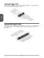
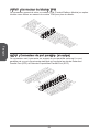
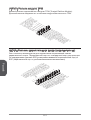
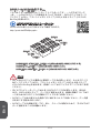
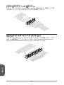
JUSB~2: USB 2.0 Expansion Connectors
This connector is designed for connecting high-speed USB peripherals such as USB
HDDs, digital cameras, MP3 players, printers, modems, and many others.
1
.
V
C
C
3
.
U
S
B
0
-
1
0
.
NC
5
.
U
S
B
0
+
7
.
G
r
o
u
n
d
9
.
N
o
P
i
n
8
.
G
r
o
u
n
d
6
.
U
S
B
1
+
4
.
U
S
B
1
-
2
.
V
C
C
Important
Note that the VCC and GND pins must be connected correctly to avoid possible
damage.
JUSB3: USB 3.0 Expansion Connector (optional)
The USB 3.0 port is backwards compatible with USB 2.0 devices. It supports data
transfer rates up to 5Gbits/s (SuperSpeed).
5.
U
SB3_TX_C_DN
4
.Ground
3.USB3_RX_DP
2.USB3_RX_DN
1.Power
10.Ground
9.
+
U
SB2.0
8.
-
U
SB2.0
7
.Ground
6.USB3_TX_C_DP
20.No
Pi
n
19.Power
18.USB3_RX_DN
17.USB3_RX_DP
16.Ground
15.USB3_TX_C_DN
14.USB3_TX_C_DP
13.Ground
12.USB2.0
-
11
. +
U
SB2.0
Important
Note that the VCC and GND pins must be connected correctly to avoid possible
damage.
To use a USB 3.0 device, you must connect the device to a USB 3.0 port through
an optional USB 3.0 compliant cable.
•
•

English
24
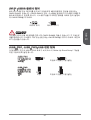
JTPM: TPM Module Connector
This connector connects to a TPM (Trusted Platform Module). Please refer to the
TPM security platform manual for more details and usages.
10.No
Pi
n
14.Ground
8.5V
P
ower
12.Ground
6.Serial
IR
Q
4.3.3V
P
ower
2.3V
Standby
p
ower
1.LP
C C
loc
k
3.LP
C
Rese
t
5.LP
C a
ddres
s &
data
pin0
7.LP
C a
ddres
s &
data
p
in1
9.LP
C a
ddres
s &
data
pin2
11
.LPC
a
ddres
s &
data
pin3
13.LP
C
Fram
e
JLPT: Parallel Port Header (optional)
This connector is used to connect an optional parallel port bracket. The parallel port
is a standard printer port that supports Enhanced Parallel Port (EPP) and Extended
Capabilities Parallel Port (ECP) mode.
1
0
.
G
r
o
u
n
d
1
4
.
G
r
o
u
n
d
8
.
L
P
T
_
S
L
I
N
#
1
2
.
G
r
o
u
n
d
6
.
P
I
N
I
T
#
4
.
E
R
R
#
2
.
A
F
D
#
2
4
.
G
r
o
u
n
d
2
2
.
G
r
o
u
n
d
2
6
.
N
o
P
i
n
2
0
.
G
r
o
u
n
d
1
8
.
G
r
o
u
n
d
1
6
.
G
r
o
u
n
d
1
.
R
S
T
B
#
3
.
P
R
N
D
0
5
.
P
R
N
D
1
7
.
P
R
N
D
2
9
.
P
R
N
D
3
1
1
.
P
R
N
D
4
1
3
.
P
R
N
D
5
1
5
.
P
R
N
D
6
1
7
.
P
R
N
D
7
1
9
.
A
C
K
#
2
1
.
B
U
S
Y
2
3
.
P
E
2
5
.
S
L
C
T

English
25
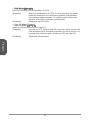
JBAT: Clear CMOS Jumper
There is CMOS RAM onboard that is external powered from a battery located on the
motherboard to save system conguration data. With the CMOS RAM, the system
can automatically boot into the operating system (OS) every time it is turned on. If
you want to clear the system conguration, set the jumpers to clear the CMOS RAM.
Keep Data Clear Data
Important
You can clear the CMOS RAM by shorting this jumper while the system is o.
Afterwards, open the jumper . Do not clear the CMOS RAM while the system is on
because it will damage the motherboard.
JUSB_PW, JUSB_PW2: USB Power Jumper
These jumpers are used to assign which USB and PS/2 ports could support “Wake
Up Event Setup” eld of BIOS.
JUSB_PW2
(for back panel
USB ports & PS/2
ports)
JUSB_PW
(for onboard USB
connectors)
Support No Support (Default)
Support No Support (Default)
Page is loading ...
Page is loading ...
Page is loading ...
Page is loading ...
Page is loading ...
Page is loading ...
Page is loading ...
Page is loading ...
Page is loading ...
Page is loading ...
Page is loading ...
Page is loading ...
Page is loading ...
Page is loading ...
Page is loading ...
Page is loading ...
Page is loading ...
Page is loading ...
Page is loading ...
Page is loading ...
Page is loading ...
Page is loading ...
Page is loading ...
Page is loading ...
Page is loading ...
Page is loading ...
Page is loading ...
Page is loading ...
Page is loading ...
Page is loading ...
Page is loading ...
Page is loading ...
Page is loading ...
Page is loading ...
Page is loading ...
Page is loading ...
Page is loading ...
Page is loading ...
Page is loading ...
Page is loading ...
Page is loading ...
Page is loading ...
Page is loading ...
Page is loading ...
Page is loading ...
Page is loading ...
Page is loading ...
Page is loading ...
Page is loading ...
Page is loading ...
Page is loading ...
Page is loading ...
Page is loading ...
Page is loading ...
Page is loading ...
Page is loading ...
Page is loading ...
Page is loading ...
Page is loading ...
Page is loading ...
Page is loading ...
Page is loading ...
Page is loading ...
Page is loading ...
Page is loading ...
Page is loading ...
Page is loading ...
Page is loading ...
Page is loading ...
Page is loading ...
Page is loading ...
Page is loading ...
Page is loading ...
Page is loading ...
Page is loading ...
Page is loading ...
Page is loading ...
Page is loading ...
Page is loading ...
Page is loading ...
Page is loading ...
Page is loading ...
Page is loading ...
Page is loading ...
Page is loading ...
Page is loading ...
Page is loading ...
Page is loading ...
Page is loading ...
Page is loading ...
Page is loading ...
Page is loading ...
Page is loading ...
Page is loading ...
Page is loading ...
Page is loading ...
Page is loading ...
Page is loading ...
Page is loading ...
Page is loading ...
Page is loading ...
Page is loading ...
Page is loading ...
Page is loading ...
Page is loading ...
Page is loading ...
Page is loading ...
Page is loading ...
Page is loading ...
Page is loading ...
Page is loading ...
Page is loading ...
Page is loading ...
Page is loading ...
Page is loading ...
Page is loading ...
Page is loading ...
Page is loading ...
Page is loading ...
Page is loading ...
Page is loading ...
Page is loading ...
Page is loading ...
Page is loading ...
Page is loading ...
Page is loading ...
Page is loading ...
Page is loading ...
Page is loading ...
Page is loading ...
Page is loading ...
Page is loading ...
Page is loading ...
Page is loading ...
Page is loading ...
Page is loading ...
Page is loading ...
Page is loading ...
Page is loading ...
Page is loading ...
Page is loading ...
Page is loading ...
Page is loading ...
Page is loading ...
Page is loading ...
Page is loading ...
Page is loading ...
Page is loading ...
Page is loading ...
Page is loading ...
Page is loading ...
Page is loading ...
Page is loading ...
Page is loading ...
Page is loading ...
Page is loading ...
Page is loading ...
Page is loading ...
Page is loading ...
Page is loading ...
Page is loading ...
-
 1
1
-
 2
2
-
 3
3
-
 4
4
-
 5
5
-
 6
6
-
 7
7
-
 8
8
-
 9
9
-
 10
10
-
 11
11
-
 12
12
-
 13
13
-
 14
14
-
 15
15
-
 16
16
-
 17
17
-
 18
18
-
 19
19
-
 20
20
-
 21
21
-
 22
22
-
 23
23
-
 24
24
-
 25
25
-
 26
26
-
 27
27
-
 28
28
-
 29
29
-
 30
30
-
 31
31
-
 32
32
-
 33
33
-
 34
34
-
 35
35
-
 36
36
-
 37
37
-
 38
38
-
 39
39
-
 40
40
-
 41
41
-
 42
42
-
 43
43
-
 44
44
-
 45
45
-
 46
46
-
 47
47
-
 48
48
-
 49
49
-
 50
50
-
 51
51
-
 52
52
-
 53
53
-
 54
54
-
 55
55
-
 56
56
-
 57
57
-
 58
58
-
 59
59
-
 60
60
-
 61
61
-
 62
62
-
 63
63
-
 64
64
-
 65
65
-
 66
66
-
 67
67
-
 68
68
-
 69
69
-
 70
70
-
 71
71
-
 72
72
-
 73
73
-
 74
74
-
 75
75
-
 76
76
-
 77
77
-
 78
78
-
 79
79
-
 80
80
-
 81
81
-
 82
82
-
 83
83
-
 84
84
-
 85
85
-
 86
86
-
 87
87
-
 88
88
-
 89
89
-
 90
90
-
 91
91
-
 92
92
-
 93
93
-
 94
94
-
 95
95
-
 96
96
-
 97
97
-
 98
98
-
 99
99
-
 100
100
-
 101
101
-
 102
102
-
 103
103
-
 104
104
-
 105
105
-
 106
106
-
 107
107
-
 108
108
-
 109
109
-
 110
110
-
 111
111
-
 112
112
-
 113
113
-
 114
114
-
 115
115
-
 116
116
-
 117
117
-
 118
118
-
 119
119
-
 120
120
-
 121
121
-
 122
122
-
 123
123
-
 124
124
-
 125
125
-
 126
126
-
 127
127
-
 128
128
-
 129
129
-
 130
130
-
 131
131
-
 132
132
-
 133
133
-
 134
134
-
 135
135
-
 136
136
-
 137
137
-
 138
138
-
 139
139
-
 140
140
-
 141
141
-
 142
142
-
 143
143
-
 144
144
-
 145
145
-
 146
146
-
 147
147
-
 148
148
-
 149
149
-
 150
150
-
 151
151
-
 152
152
-
 153
153
-
 154
154
-
 155
155
-
 156
156
-
 157
157
-
 158
158
-
 159
159
-
 160
160
-
 161
161
-
 162
162
-
 163
163
-
 164
164
-
 165
165
-
 166
166
-
 167
167
-
 168
168
-
 169
169
-
 170
170
-
 171
171
-
 172
172
-
 173
173
-
 174
174
-
 175
175
-
 176
176
-
 177
177
-
 178
178
-
 179
179
-
 180
180
-
 181
181
-
 182
182
-
 183
183
-
 184
184
-
 185
185
-
 186
186


MSI MS-7721v6.0 Owner's manual
- Category
- Motherboards
- Type
- Owner's manual
- This manual is also suitable for
Ask a question and I''ll find the answer in the document
Finding information in a document is now easier with AI
in other languages
- français: MSI MS-7721v6.0 Le manuel du propriétaire
- Deutsch: MSI MS-7721v6.0 Bedienungsanleitung
- русский: MSI MS-7721v6.0 Инструкция по применению
- 日本語: MSI MS-7721v6.0 取扱説明書