Page is loading ...


PCI Express Board User’s Manual
The software described in this manual is furnished under a license agreement and may be used only in
accordance with the terms of that agreement.
Copyright Notice
Copyright © 2006 MOXA Technologies Co., Ltd.
All rights reserved.
Reproduction without permission is prohibited.
Trademarks
MOXA is a registered trademark of The MOXA Group.
All other trademarks or registered marks in this manual belong to their respective manufacturers.
Disclaimer
Information in this document is subject to change without notice and does not represent a commitment on the
part of MOXA.
MOXA provides this document “as is,” without warranty of any kind, either expressed or implied, including, but
not limited to, its particular purpose. MOXA reserves the right to make improvements and/or changes to this
manual, or to the products and/or the programs described in this manual, at any time.
Information provided in this manual is intended to be accurate and reliable. However, MOXA assumes no
responsibility for its use, or for any infringements on the rights of third parties that may result from its use.
This product might include unintentional technical or typographical errors. Changes are periodically made to the
information herein to correct such errors, and these changes are incorporated into new editions of the
publication.

Table of Contents
Chapter 1 Introduction..................................................................................................1-1
Overview.................................................................................................................................. 1-2
Applications............................................................................................................................. 1-3
Features.................................................................................................................................... 1-3
Package Checklist.................................................................................................................... 1-3
Installation Flowchart.............................................................................................................. 1-4
Chapter 2 Hardware Installation...................................................................................2-1
CP-118EL Dimensions............................................................................................................. 2-2
DIP Switch Settings (CP-118EL only)..................................................................................... 2-2
CP-168EL Dimensions ............................................................................................................ 2-3
CP-104EL Dimensions ............................................................................................................ 2-3
Plugging the Board into an Expansion Slot ............................................................................. 2-4
Chapter 3 Software Installation....................................................................................3-1
Windows Drivers..................................................................................................................... 3-2
Windows 2003/XP (32 bit/64 bit)................................................................................. 3-3
Windows 2000............................................................................................................ 3-17
Non-Windows Drivers........................................................................................................... 3-32
DOS............................................................................................................................ 3-32
Linux (32 bit/64 bit) ................................................................................................... 3-35
SCO ............................................................................................................................ 3-37
Chapter 4 Serial Programming Tools ..........................................................................4-1
MOXA PComm ....................................................................................................................... 4-2
Installing PComm......................................................................................................... 4-2
PComm Programming Library..................................................................................... 4-2
Utilities .................................................................................................................................... 4-2
Diagnostics (for MOXA boards only) .......................................................................... 4-2
Monitor (for MOXA boards under Windows NT/2000/XP/2003)............................... 4-3
Terminal Emulator........................................................................................................4-4
RS-485 Programming .............................................................................................................. 4-4
ADDC™....................................................................................................................... 4-4
Chapter 5 Pin Assignments..........................................................................................5-1
CP-118EL ................................................................................................................................ 5-2
Board Side Pin Assignments—Female SCSI VHDCI68.............................................. 5-2
Device Side Pin Assignments....................................................................................... 5-3
CP-168EL................................................................................................................................ 5-5
Board Side Pin Assignments—Female SCSI VHDCI68.............................................. 5-5
Device Side Pin Assignments....................................................................................... 5-6
CP-104EL................................................................................................................................ 5-8
Board Side Pin Assignments—Female DB44 .............................................................. 5-8
Device Side Pin Assignments....................................................................................... 5-8
Chapter 6 Troubleshooting...........................................................................................6-1
General Troubleshooting.......................................................................................................... 6-1
Appendix A Technical Reference...................................................................................A-1
Product Specifications ............................................................................................................ A-1
CP-118EL Specifications............................................................................................. A-1
CP-168EL Specifications............................................................................................. A-2

CP-104EL Specifications............................................................................................. A-2
PCI Express ............................................................................................................................ A-3
MOXA UART......................................................................................................................... A-3
Appendix B Service Information.....................................................................................B-1
MOXA Internet Services..........................................................................................................B-2
Problem Report Form ..............................................................................................................B-3
Product Return Procedure........................................................................................................B-4

1
1
Chapter 1 Introduction
MOXA’s PCI Express serial boards meet the new slot standard for expansion boards, and work
with any PCI Express slots. The boards have multiple RS-232/422/485 serial ports for connecting
data acquisition equipment and other serial devices to a PC.
This chapter covers the following topics:
Overview
Applications
Features
Package Checklist
Installation Flowchart

PCI Express Board User’s Manual Introduction
1-2
Overview
MOXA’s new PCI Express Multiport Serial Boards, named CP-118EL, CP-168EL, and CP-104EL,
are designed for POS and ATM applications and for use by industrial automation system
manufacturers and system integrators. The boards are compatible with all popular operating
systems, and each of them supports data rates of up to 921.6 Kbps, and provides full modem
control signals, ensuring compatibility with a wide range of serial peripherals. In addition,
CP-118EL, CP-168EL, and CP-104EL work with PCI Express ×1, allowing the boards to be
installed in any available PCI Express slot (including ×1, ×2, ×4, ×8, ×16, ×32).
PCI Express Solution
The boards comply with PCI Express Spec. 1.1. The serial transmission mode (RS-232, RS-422,
2-wire RS-485, or 4-wire RS-485) for each port is set with onboard switches (CP-118EL has DIP
Switches, CP-168EL and CP-104EL are RS-232 only), but the ports’ transmission parameters are
configured after the boards are installed. The PCI BIOS automatically assigns the IRQ and I/O
addresses. For this reason, you must plug the boards into the computer before installing the drivers.
For more PCI Express information, refer to the “Technical Reference” appendix.
Surge Protection
The PCI Express boards come with built-in 15 KV ESD surge protection to prevent damage to the
boards from lightning or high potential voltage. The surge protection feature makes the PCI
Express boards suitable for industrial, factory-type applications, and for use with applications that
are subject to severe weather conditions.
ADDC™ (Automatic Data Direction Control) for RS-485
To make 2-wire RS-485 half-duplex connections easier to manage, ADDC™ (Automatic Data
Direction Control) intelligence is built into the CP-118EL board, eliminating the need for software
interference. Windows applications can be set up to manage RS-485 ports without writing
additional code to control the half-duplex protocol.
Operating System Support
The PCI Express boards are compatible with all major industrial platforms, including Windows
2000/XP/2003, DOS, and Linux. MOXA device drivers are provided for smoother installation,
configuration, and performance. In this manual, we provide installation details for Windows
2003/XP, Windows 2000, DOS, Linux, and SCO.
Visit MOXA’s website at
www.moxa.com to download the latest drivers and user’s manuals for all
of MOXA’s products.
MOXA Serial Comm Tool
For application development, MOXA provides an easy-to-use serial communication library called
PComm that runs under Windows NT/2000/XP/2003/95/98. Use this library to develop your own
applications with Visual Basic, Visual C++, Borland Delphi, etc. Utilities, such as Data Scope,
Monitor, Terminal Emulator, and Diagnostics are included to make it easier to debug, monitor
communication status, provide terminal emulation, and transfer files.

PCI Express Board User’s Manual Introduction
1-3
Applications
The PCI Express boards are suitable for many different applications, including:
y Internet/Intranet Connections
y Remote Access
y Multi-user Applications
y Industrial Automation
y Office Automation
y Telecommunications
y PC-based Vending Machines and Kiosks
y POS (Point-of-Sale) Systems
Features
The PCI Express boards have the following outstanding features:
y PCI Express ×1 compliant
y Low profile board for compact-sized PCs
y Data flow LED display onboard
y MOXA UART with 128-byte FIFO driver
y 50 bps to 921.6 Kbps transmission speed
y Supports both 4-wire and 2-wire RS-485 (CP-118EL)
y 2-wire RS-485 data control with ADDC™ (CP-118EL)
y Embedded 15 KV ESD surge protection
y Drivers for all major industrial platforms—Windows 2000, Windows XP/2003 (32-bit/64-bit),
DOS, Linux (32-bit/64-bit), SCO, FreeBSD 4.x/5.x
Package Checklist
The following items are included in the PCI Express board package:
y PCI Express serial board
y Documentation and Software CD-ROM
y Quick Installation Guide
y Low profile bracket
NOTE: Notify your sales representative if any of the above items are missing or damaged.

PCI Express Board User’s Manual Introduction
1-4
Installation Flowchart
The following flowchart provides a brief summary of the procedure you should follow to install
the PCI Express boards and also provides references to chapters with more detailed information:
Use the onboard DIP Switches to select the
data transmission mode for each port.
(CP-118EL only)
Chapter 2, “Hardware Installation”
Install the boards in PCI Express expansion
slots.
Chapter 2, “Hardware Installation”
Install the drivers and configure the boards
and ports.
Chapter 3, “Software Installation”
Connect the serial devices to the PCI
Express board’s serial ports.
Chapter 5, “Pin Assignments”
Restart the system, and check the driver
initialization status.
Chapter 3, “Software Installation”
Develop and run your serial
communication applications
Chapter 4, “Serial Programming Tools”

2
2
Chapter 2 Hardware Installation
This chapter describes the PCI Express Series hardware installation procedure. Since the BIOS
automatically assigns the PCI Express board’s IRQ number and I/O addresses, you must plug in
the board before installing the driver.
This chapter covers the following topics:
CP-118EL Dimensions
DIP Switch Settings (CP-118EL only)
CP-168EL Dimensions
CP-104EL Dimensions
Plugging the Board into an Expansion Slot

PCI Express Board User’s Manual Hardware Installation
2-2
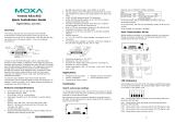
CP-118EL Dimensions
132 mm (5.20 in)
51.65 mm
(2.03 in)
MU860
TX2
RX1 RX2
Tx3
Rx3
Tx4
Rx4
Tx5 Tx6
Rx5
Rx6
Tx7
Rx7
Tx8
Rx8
TX1
DIP
12345678
ON
DIP
12345678
ON
DIP
12345678
ON
S1
S2
S3
Mode
S1 S2 S3
RS-232
RS-422
ON
ON OFF
Mode
S1 S2 S3
4-WIRE
RS-485
2-WIRE
RS-485
OFF
OFF OFF
OFFON OFF
46.9 mm (1.85 in)
64.41 mm
(2.54 in)
59.91 mm
(2.36 in)
121 mm
(4.76 in)
NOTE: Use JP1/2/3/4/5/6/7/8 to activate the Termination Resistors for ports 1/2/3/4/5/6/7/8.
Open Termination Resistor is NOT active
Short Termination Resistor is ACTIVE
DIP Switch Settings (CP-118EL only)
CP-118EL has three onboard DIP Switch arrays, each with 8 switches, shown as follows and on
the board (see the above block diagram) as S1, S2, and S3. The switches are used to select one of
four serial interfaces—RS-232, RS-422, 4-wire RS-485, 2-wire RS-485—for each of the eight
ports. Note that S3 selects between RS-232 and RS-422/485, S2 selects between RS-422 and
RS-485, and S3 selects between 2-wire and 4-wire RS-485.
Mode S1 S2 S3
RS-232 --- --- ON
RS-422 --- ON OFF
4-Wire RS-485 ON OFF OFF
2-Wire RS-485 OFF OFF OFF

PCI Express Board User’s Manual Hardware Installation
2-3
CP-168EL Dimensions
102 mm (4.02 in)
MU860
TX2
RX1 RX2
Tx3
Rx3
Tx4
Rx4
Tx5 Tx6
Rx5
Rx6
Tx7
Rx7
Tx8
Rx8
TX1
67.21 mm
(2.65 in)
54.45 mm
(2.14 in)
62.71 mm
(2.47 in)
46.9 mm
(1.85 in)
121 mm
(4.76 in)
CP-104EL Dimensions
100 mm (3.94 in)
54.51 mm
(2.15 in)
MU860
TX2
RX1 RX2
Tx3
Rx3
Tx4
Rx4
TX1
CP-104EL
62.71 mm
(2.47 in)
121 mm
(4.76 in)
46.9 mm
(1.85 in)
67.27 mm
(2.65 in)

PCI Express Board User’s Manual Hardware Installation
2-4
Plugging the Board into an Expansion Slot
Since the BIOS automatically assigns the PCI Express board’s IRQ number and I/O addresses, you
must plug the board into one of the computer’s expansion slots before installing the driver.
Step 1: Power off the PC.
WARNING
To avoid damaging your system and board, make sure you turn off your computer before
installing the board.
Step 2: Remove the PC’s cover.
Step 3: Remove the slot cover bracket if there is one.
Step 4: Use the onboard DIP Switches to set the transmission mode for each port (see the
previous section for details); (CP-118EL only)
Step 5: Plug the PCI Express board firmly into a free PCI Express slot.
Step 6: Fasten the holding screw to fix the control board in place.
Step 7: Replace the PC’s cover.
Step 8: Power on the PC. The BIOS will automatically set the IRQ and I/O address.
NOTE
Each MOXA PCI Express board uses one unique IRQ and I/O address, both of which are
assigned automatically by the PCI BIOS.
Step 9: Proceed with the software installation discussed in the next chapter, “Software
Installation.”

3
3
Chapter 3 Software Installation
This chapter gives installation, configuration, and update/removal procedures for the driver for
Windows 2000, Windows 2003/XP (32-bit/64-bit), DOS, Linux (32-bit/64-bit), and SCO. Before
proceeding with the software installation, complete the hardware installation discussed in the
previous chapter, “Hardware Installation.”
Refer to the next chapter, “Serial Programming Tools,” for information about developing your own
serial programming applications. Note that you can install up to 4 PCI Express boards in one
system, provided sufficient I/O address and IRQ number resources are available.
You can download the Windows 2000/XP/2003, DOS, Linux, and SCO drivers from the MOXA
website.
This chapter covers the following topics:
Windows Drivers
¾ Windows 2003/XP (32 bit/64 bit)
¾ Windows 2000
Non-Windows Drivers
¾ DOS
¾ Linux (32 bit/64 bit)
¾ SCO

PCI Express Board User’s Manual Serial Programming Tools
3-2
Windows Drivers
MOXA provides drivers that allow you to use the following serial board products under Windows
2003/XP/2000, Windows 98/95, and Windows NT. Windows 95/98/NT do not support PCI
Express drivers.
y PCI Express Boards: CP-118EL, CP-168EL, CP-104EL
y Universal PCI Boards: CP-118U, CP-168U, CP-104UL, CP-104JU, CP-102U, CP-102UL,
CP-134U, CP-134U-I, CP-132UL, CP-132UL-I V2 (CP-132U-I V1)
y PCI Boards: C168H/PCI, C104H/PCI, C104HS/PCI, CP-114, CP-114I, CP-114S, CP-114IS,
CP-132, CP-132I, CP-132S, CP-132IS
y ISA Boards: C168H, C168HS, C168P, C104H, C104HS, C104P, CI-104J, CI-104JS, CI-134,
CI-134I, CI-134IS, CI-132, CI-132I, CI-132IS
y cPCI Boards: CT-114I
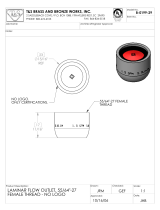
The overall procedure for
installing the Windows drivers
for the PCI Express boards is
summarized in the flowchart on
the right.
Plug the PCI Express board into an
empty PCI Express slot. See the
Hardware Installation chapter.
Driver already installed?
Install the driver from the
Documentation and Software CD. See
the Installing the Driver for the First
Time subsection for detailed
instructions.
Configure the board’s ports. See the
Configuring the Ports subsection for
detailed instructions.
The PCI Express board and ports are
ready to use.
Turn on your PC. Windows will
automatically detect the board.
Yes
N
o

PCI Express Board User’s Manual Serial Programming Tools
3-3
WARNING
If you are installing a PCI Express board on an ASUS A8N Series (AMD CPU) motherboard and
the installation process hangs the first time, then restart the PC to reinstall it.
NOTE
The following steps use CP-118EL as an example. The installation process for CP-168EL and
CP-104EL are the same.
Windows 2003/XP (32-bit/64-bit)
In this section, we describe the installation procedure for Windows XP. The installation procedure
for Windows 2003 is similar.
Windows 2003/XP support up to 256 serial ports, from COM1 to COM256. In order to make the
best use of Windows 2003/XP’s multi-process/multi-thread advanced features, 32-bit and 64-bit
Windows 2003/XP device drivers were developed for MOXA multiport boards. The drivers
conform to the Win32 COMM API standard.
Installing the Driver
The following procedure shows how to install the CP-118EL driver for the first time under
Windows XP. First, make sure that you have already plugged the board or boards into the system’s
PCI Express slot(s).
NOTE
If you have already installed a CP-118EL or other MOXA PCI Express board in your computer,
and you are installing additional boards, Windows 2003/XP will automatically detect and install
the new board(s) the next time you boot up the computer. In this case, proceed directly to the next
section, “Configuring the Ports,” to configure the ports’ serial transmission parameters.
1. After plugging the board into an expansion slot and powering on your PC, Windows XP will
automatically detect the new board, and the Found New Hardware balloon will open in the
bottom right corner of the Windows desktop.

PCI Express Board User’s Manual Serial Programming Tools
3-4
2. The Welcome to the Found New Hardware Wizard window will open automatically. This
window will offer to connect to the Windows update site to search for a driver. Select No, not
at this time and click Next to continue.
3. Select Install from a list or specific location (Advanced), and then click Next to continue

PCI Express Board User’s Manual Serial Programming Tools
3-5
4. Select Search for the best driver in these locations, select Include this location in the
search, and then click Browse. If the system is a 32-bit (x86) platform, navigate to the
\CP-118EL\Software\Windows XP_2003\x86 folder on the CD. If the system is a 64-bit
(x64) platform, navigate to the \CP-118EL\Software\Windows XP_2003\x64 folder on the
CD, and then click Next to continue.
The following figure shows the path for x86.
The following figure shows the path for x64.

PCI Express Board User’s Manual Serial Programming Tools
3-6
5. Wait while the installation wizard searches for the correct drivers. The next window that
opens cautions you that although this software has not passed Windows Logo testing, the
driver has been tested and shown that it can support the Windows OS. Click Continue
Anyway to proceed.
6. Wait while the driver software is installed.

PCI Express Board User’s Manual Serial Programming Tools
3-7
7. The next window shows the model name of the board, and indicates that Windows has
completed the driver installation. Click Finish to proceed with the rest of the installation
procedure.
8. The Found New Hardware Wizard window will open to help you install the driver for
MOXA Port 0. This window will offer to connect to the Windows update site to search for a
driver. Select No, not at this time and then click Next to continue.

PCI Express Board User’s Manual Serial Programming Tools
3-8
9. Select Install from a list or specific location (Advanced), and then click Next to proceed.
10. Select Search for the best driver in these locations, select Include this location in the
search, and then click Browse. If necessary, use the Browse button to navigate to the
\CP-118EL\Software\Windows XP_2003\x86 folder (32 bit platform) or
\CP-118EL\Software\Windows XP_2003\x64 folder (64 bit platform), and then click Next
to proceed.
The following figure shows the path for x86.
/