Sony RDR-GX7 Operating instructions
- Category
- DVD players
- Type
- Operating instructions

3-081-196-12(2)
Hookups and Settings
© 2003 Sony Corporation
RDR-GX7
DVD Recorder

2
WARNING
WARNING
To prevent fire or shock hazard, do not
expose the unit to rain or moisture.
To avoid electrical shock, do not open
the cabinet. Refer servicing to qualified
personnel only.
Mains lead must only be changed at a
qualified service shop.
This appliance is classified as a CLASS
1 LASER product. The CLASS 1
LASER PRODUCT MARKING is
located on the rear exterior.
CAUTION
The use of optical instruments with this
product will increase eye hazard. As the
laser beam used in this DVD recorder is
harmful to eyes, do not attempt to
disassemble the cabinet.
Refer servicing to qualified personnel
only.
This label is located on the laser
protective housing inside the enclosure.
Notice for customers in the United
Kingdom and Republic of Ireland
A moulded plug complying with
BS1363 is fitted to this equipment for
your safety and convenience.
Should the fuse in the plug supplied need
to be replaced, a 5 AMP fuse approved
by ASTA or BSI to BS1362, (i.e.,
marked with or mark) must be
used.
If the plug supplied with this equipment
has a detachable fuse cover, be sure to
attach the fuse cover after you change
the fuse. Never use the plug without the
fuse cover. If you should lose the fuse
cover, please contact your nearest Sony
service station.
Precautions
• This unit operates on 220 – 240 V AC,
50/60 Hz. Check that the unit’s
operating voltage is identical with your
local power supply.
• To prevent fire or shock hazard, do not
place objects filled with liquids, such
as vases, on the apparatus.
VIDEO Plus+ and PlusCode are
registered trademarks of Gemstar
Development Corporation. The VIDEO
Plus+ system is manufactured under
license from Gemstar Development
Corporation.
Precautions
This equipment has been tested and
found to comply with the limits set out in
the EMC Directive using a connection
cable shorter than 3 metres.
On safety
Should any solid object or liquid fall into
the cabinet, unplug the recorder and have
it checked by qualified personnel before
operating it any further.
On power sources
• The recorder is not disconnected from
the AC power source (mains) as long as
it is connected to the wall outlet, even
if the recorder itself has been turned
off.
• If you are not going to use the recorder
for a long time, be sure to disconnect
the recorder from the wall outlet. To
disconnect the AC power cord (mains
lead), grasp the plug itself; never pull
the cord.
On placement
• Place the recorder in a location with
adequate ventilation to prevent heat
build-up in the recorder.
• Do not place the recorder on a soft
surface such as a rug that might block
the ventilation holes.
• Do not place the recorder in a confined
space such as a bookshelf or similar
unit.
• Do not place the recorder in a location
near heat sources, or in a place subject
to direct sunlight, excessive dust, or
mechanical shock.
• Do not place the recorder in an inclined
position. It is designed to be operated
in a horizontal position only.
• Keep the recorder and discs away from
equipment with strong magnets, such
as microwave ovens, or large
loudspeakers.
• Do not place heavy objects on the
recorder.
On operation
• If the recorder is brought directly from
a cold to a warm location, or is placed
in a very damp room, moisture may
condense on the lenses inside the
recorder. Should this occur, the
recorder may not operate properly. In
this case, remove the disc and leave the
recorder turned on for about half an
hour until the moisture evaporates.
• When you move the recorder, take out
any discs. If you don’t, the disc may be
damaged.
On recording
• Contents of the recording cannot be
compensated if the recording or
playback is not made due to a
malfunction of the recorder, disc, etc.
• Make trial recordings before taking the
actual recording.
On adjusting volume
Do not turn up the volume while
listening to a section with very low level
inputs or no audio signals. If you do, the
speakers may be damaged when a peak
level section is played.
On cleaning
Clean the cabinet, panel, and controls
with a soft cloth slightly moistened with
a mild detergent solution. Do not use any
type of abrasive pad, scouring powder or
solvent such as alcohol or benzine.
On cleaning discs
Do not use a commercially available
cleaning disc. It may cause a malfunction.
Copyrights
• Television programmes, films, video
tapes, discs and other materials may be
copyrighted. Unauthorized recording
of such material may be contrary to the
provisions of the copyright laws. Also,
use of this recorder with cable
television transmission may require
authorization from the cable television
transmitter and/or programme owner.
• This product incorporates copyright
protection technology that is protected
by method claims of certain U.S.
patents, other intellectual property
rights owned by Macrovision
Corporation, and other rights owners.
Use of this copyright protection
technology must be authorized by
Macrovision Corporation, and is
intended for home and other limited
viewing uses only unless otherwise
authorized by Macrovision
Corporation. Reverse engineering or
disassembly is prohibited.
Copy guard function
Since the recorder has a copy guard
function, programmes received through
an external tuner (not supplied) may
contain copy protection signals (copy
guard function) and as such may not be
recordable, depending on the type of
signal.
DANGER
VISIBLE AND INVISIBLE LASER RADIATION WHEN OPEN.
AVOID DIRECT EXPOSURE TO BEAM.
RAYONNEMENT VISIBLE ET INVISIBLE EN CAS D’OUVERTURE.
EXPOSITION DANGERUSE AU FAISCEAU.
SICHTBARE UND UNSICHTBARE LASERSTRAHLUNG, WENN ABDECKUNG GEÖFFNET.
NICHT DEM STRAHL AUSSETZEN.
UNDGÅ UDSÆTTELSE FOR STRÅLING.
SYNLIG OG USYNLIG LASERSTRÅLING VED ÅBNING.
UNNGÅ EKSPONERING FOR STRÅLEN.
SYNLIG OG USYNLIG LASERSTRÅLING NÅR DEKSEL ÅPNES.
SYNLIG OCH OSYNLIG LASERSTRÅLNING NÄR DENNA DEL ÄR ÖPPNAD.
STRÅLEN ÄR FARLIG.
NÄKYVÄÄ JA NÄKYMÄTÖN AVATTAESSA OLET ALTTIINA LASERSÄTEILYLLE.
ÄLÄ KATSO SÄTEESEN.
ATTENTION
VORSICHT
ADVARSEL
ADVARSEL
VARNING
VAR O!

3
Precautions
Music discs encoded with
copyright protection
technologies
This product is designed to playback
discs that conform to the Compact Disc
(CD) standard.
Recently, various music discs encoded
with copyright protection technologies
are marketed by some record companies.
Please be aware that among those discs,
there are some that do not conform to the
CD standard and may not be playable by
this product.
If you have any questions or problems
concerning your recorder, please consult
your nearest Sony dealer.
Notes about the Discs
• To keep the disc clean, handle the disc
by its edge. Do not touch the surface.
Dust, fingerprints, or scratches on the
disc may cause it to malfunction.
• Do not expose the disc to direct
sunlight or heat sources such as hot air
ducts, or leave it in a car parked in
direct sunlight as the temperature may
rise considerably inside the car.
• After playing, store the disc in its case.
• Clean the disc with a cleaning cloth.
Wipe the disc from the centre out.
• Do not use solvents such as benzine,
thinner, commercially available
cleaners, or anti-static spray intended
for vinyl LPs.
• Do not use the following discs.
–A disc that has a non-standard shape
(e.g., card, heart).
–A disc with a label or sticker on it.
–A disc that has cellophane tape or
sticker adhesive on it.
Table of
Contents
WARNING ...........................2
Precautions ........................2
Basic Hookups and
Settings
Quick Overview ..................4
Step 1: Unpacking ..............5
Step 2: Connecting the Aerial
Cable ..............................5
Step 3: Connecting the Video
Cords ..............................5
Step 4: Connecting the
Audio Cords ..................7
Step 5: Connecting the
Mains Lead ..................10
Step 6: Preparing the
Remote .........................10
Step 7: Easy Setup ...........11
Advanced Hookups
and Settings
Setting the Clock ..............14
Presetting Channels ........16
Changing/Disabling the
Channels ......................19
Controlling Your TV or AV
Amplifier (Receiver) ....21
Connecting a VCR or Similar
Recording Device to the
LINE3 Jack ...................22
Connecting to a Satellite or
Digital Tuner ................23
Connecting a PAY-TV/Canal
Plus Decoder ...............24
Index ..................................26
IMPORTANT NOTICE
Caution: This recorder is capable of
holding a still video image or on-screen
display image on your television screen
indefinitely. If you leave a still video
image or on-screen display image
displayed on your TV for an extended
period of time, you risk permanent
damage to your television screen.
Plasma Display Panels and Projection
televisions are especially susceptible to
this.
When you have finished with hookups
and settings, refer to the Operating
Instructions for further instructions.
“Troubleshooting,” “Specifications,”
and “Guide to Parts and Controls” can
also be found in the Operating
Instructions.

4
Quick Overview
Basic Hookups
and Settings
Quick Overview
A quick overview presented in this guide will give you enough
information to start using the recorder.
Notes
• You cannot connect this recorder to a TV that does not have a SCART
(EURO AV) or video input jack.
• Be sure to disconnect the mains lead of each component before
connecting.
Step 1: Unpacking
m
Step 2: Connecting the Aerial Cable
m
Step 3: Connecting the Video Cords
m
Step 4: Connecting the Audio Cords
m
Step 5: Connecting the Mains Lead
m
Step 6: Preparing the Remote
m
Step 7: Easy Setup
• Quick Overview. . . . . . . . . . . . . . . . . . . page 4
• Step 1: Unpacking. . . . . . . . . . . . . . . . . page 5
• Step 2: Connecting the Aerial Cable . . . page 5
• Step 3: Connecting the Video Cords . . . page 5
• Step 4: Connecting the Audio Cords. . . page 7
• Step 5: Connecting the Mains Lead
. . . . . . . . . . . . . . . . . . . . . . . . . . . . page 10
• Step 6: Preparing the Remote. . . . . . . page 10
• Step 7: Easy Setup . . . . . . . . . . . . . . . page 11

5
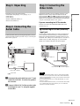
Step 1: Unpacking
Basic Hookups and Settings
Step 1: Unpacking
Check that you have the following items:
• Audio/video cord (pinplug × 3 y pinplug × 3) (1)
•Mains lead (1)
• Aerial cable (1)
• Remote commander (remote) (1)
• R6 (size AA) batteries (2)
Step 2: Connecting the
Aerial Cable
Connect the aerial cable by following the steps below. Do not
connect the mains lead until you reach “Step 5: Connecting the
Mains Lead” (page 10).
a Disconnect the aerial cable from your TV and
connect it to AERIAL IN on the rear panel of
the recorder.
b Connect AERIAL OUT of the recorder to the
aerial input of your TV, using the supplied
aerial cable.
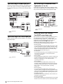
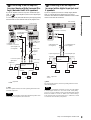
Step 3: Connecting the
Video Cords
Connect this recorder to your TV monitor, projector, or AV
amplifier (receiver) using a video cord. Select one of the
following patterns A through D, according to the input jack on
your TV monitor, projector, or AV amplifier (receiver). This will
enable you to view pictures. Audio connections are explained in
“Step 4: Connecting the Audio Cords” (page 7).
If you are connecting to a VCR or decoder
Connect your VCR to the LINE 3/DECODER jack on the
recorder (page 22).
A Connecting to a SCART (EURO AV)
input jack
Connect using a SCART (EURO AV) cord (not supplied). Be
sure to make the connections firmly to avoid hum and noise.
Refer to the operating instructions supplied with the TV to be
connected. Also, when you set “Line1 Output” to “S Video” or
“RGB” in step 17 of Easy Setup (page 13), use a SCART
(EURO AV) cord that conforms to the selected signal.
Notes
• When you connect the recorder to your TV via the SCART (EURO
AV) jacks, the TV’s input source is set to the recorder automatically
when you start playback. If necessary, press TV/DVD on the remote to
return the input to the TV.
• If you connect this recorder to a TV with SMARTLINK, set “Line1
Output” to “Video.”
• For correct SMARTLINK connection, you will need a SCART (EURO
AV) cord that has the full 21 pins. Refer to your TV’s instruction
manual as well for this connection.
~
AC IN
LINE 2 OUT
S VIDEOVIDEOR-AUDIO-L
COMPONENT
VIDEO OUT
C
B
Y
C
R
LINE 4 IN
S VIDEOVIDEOR-AUDIO-L
LINE 1 - TV
AERIAL
IN
OUT
LINE 3/DECODER
DIGITAL OUT
PCM/DTS/MPEG/
DOLBY DIGITAL
COAXIAL
OPTICAL
AERIAL
IN
OUT
DVD recorder
TV
to aerial input
to AERIAL IN
to AERIAL OUT
Aerial cable (supplied)
: Signal flow
~
AC IN
LINE 2 OUT
S VIDEOVIDEOR-AUDIO-L
COMPONENT
VIDEO OUT
C
B
Y
C
R
LINE 4 IN
S VIDEOVIDEOR-AUDIO-L
LINE 1 - TV
AERIAL
IN
OUT
LINE 3/DECODER
DIGITAL OUT
PCM/DTS/MPEG/
DOLBY DIGITAL
COAXIAL
OPTICAL
LINE 1 - TV
SCART (EURO AV) cord (not supplied)
TV
to SCART
(EURO AV) input
DVD recorder
to i LINE1-TV
,continued

6
Step 3: Connecting the Video Cords
B Connecting to a video input jack
Connect the yellow plug of the audio/video cord (supplied) to the
yellow (video) jacks. You will enjoy standard quality images.
Use the red and white plugs to connect to the audio input jacks
(page 8).
C Connecting to an S VIDEO input jack
Connect using an S VIDEO cord (not supplied). You will enjoy
high quality images.
D Connecting to component video
input jacks (Y, C
B, CR)
Connect using a component video cord (not supplied) or three
video cords (not supplied) of the same kind and length. You will
enjoy accurate colour reproduction and high quality images.
About the SMARTLINK features
(for SCART connections only)
If the connected TV complies with SMARTLINK, NexTView
Link, MEGALOGIC
1
, EASYLINK
2
, CINEMALINK
2
,
Q-Link
3
, EURO VIEW LINK
4
, or T-V LINK
5
, this recorder
automatically runs the SMARTLINK function after you
complete the connection pattern A on page 5 (the
SMARTLINK indicator lights up when you turn on your TV).
You can enjoy the following SMARTLINK features.
• Preset Download
You can download the tuner preset data from your TV to this
recorder, and tune the recorder according to that data in Easy
Setup. This greatly simplifies the Easy Setup procedure. Be
careful not to disconnect the cables or exit the Easy Setup
function during this procedure (page 11).
• TV Direct Rec
You can easily record what you are watching on your TV (see
“Recording TV programmes” in the separate booklet
“Operating Instructions”).
• One Touch Play
You can turn on the recorder and TV, set the TV’s input to the
recorder, and start playback with one touch of the H (play)
button (see “Playing Discs” in the separate booklet
“Operating Instructions”).
• One Touch Menu
You can turn on the recorder and TV, set the TV to the
recorder’s channel, and display the Title List menu with one
touch of the TITLE LIST button (see “Selecting a Recorded
Title on a Disc” in the separate booklet “Operating
Instructions”).
• One Touch Timer
You can turn on the recorder and TV, set the TV to the
recorder’s channel, and display the timer programming menu
with one touch of the TIMER button on the remote (see “Timer
Recording” in the separate booklet “Operating Instructions”).
• Automatic Power Off
The recorder will turn off automatically if the recorder is not
used after you turn off the TV.
• NexTView Download
You can easily set the timer by using the NexTView Download
function on your TV. Refer to your TV’s instruction manual.
~
AC IN
LINE 2 OUT
S VIDEOVIDEOR-AUDIO-L
COMPONENT
VIDEO OUT
C
B
Y
C
R
LINE 4 IN
S VIDEOVIDEOR-AUDIO-L
LINE 1 - TV
AERIAL
IN
OUT
LINE 3/DECODER
DIGITAL OUT
PCM/DTS/MPEG/
DOLBY DIGITAL
COAXIAL
OPTICAL
LINE 2 OUT
S VIDEOVIDEOR-AUDIO-L
AUDIO
INPUT
L
R
VIDEO
DVD recorder
to LINE 2 OUT (VIDEO)
Audio/video cord (supplied)
TV, projector, or AV
amplifier (receiver)
: Signal flow
(yellow)
(yellow)
~
AC IN
LINE 2 OUT
S VIDEOVIDEOR-AUDIO-L
COMPONENT
VIDEO OUT
C
B
Y
C
R
LINE 4 IN
S VIDEOVIDEOR-AUDIO-L
LINE 1 - TV
AERIAL
IN
OUT
LINE 3/DECODER
DIGITAL OUT
PCM/DTS/MPEG/
DOLBY DIGITAL
COAXIAL
OPTICAL
INPUT
S VIDEO
LINE 2 OUT
S VIDEOVIDEOR-AUDIO-L
DVD recorder
to LINE 2 OUT (S VIDEO)
S VIDEO cord (not supplied)
TV, projector, or AV
amplifier (receiver)
: Signal flow
~
AC IN
LINE 2 OUT
S VIDEOVIDEOR-AUDIO-L
COMPONENT
VIDEO OUT
C
B
Y
C
R
LINE 4 IN
S VIDEOVIDEOR-AUDIO-L
LINE 1 - TV
AERIAL
IN
OUT
LINE 3/DECODER
DIGITAL OUT
PCM/DTS/MPEG/
DOLBY DIGITAL
COAXIAL
OPTICAL
PR/CR
PB/CB
Y
COMPONENT
VIDEO IN
COMPONENT
VIDEO OUT
C
B
Y
C
R
DVD recorder
to COMPONENT
VIDEO OUT
(green)
(blue)
(red)
(green)
(blue)
(red)
Component video
cord (not supplied)
TV, projector, or AV
amplifier (receiver)
: Signal flow

7
Step 4: Connecting the Audio Cords
Basic Hookups and Settings
1
“MEGALOGIC” is a registered trademark of Grundig Corporation.
2
“EASYLINK” and “CINEMALINK” are trademarks of Philips
Corporation.
3
“Q-Link” is a trademark of Panasonic Corporation.
4
“EURO VIEW LINK” is a trademark of Toshiba Corporation.
5
“T-V LINK” is a trademark of JVC Corporation.
z Hint
SMARTLINK also works with TVs having EPG Timer Control and
Now Recording functions. For details, refer to the operating instructions
supplied with your TV.
Notes
• SMARTLINK features are not available for devices connected via the
DVD recorder’s LINE 3/DECODER jack.
• Not all TVs respond to the functions above.
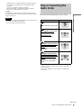
Step 4: Connecting the
Audio Cords
Select the connection that best suits your system. Be sure to read
the instructions for the components you wish to connect.
1
Manufactured under license from Dolby laboratories.
“Dolby,” “Pro Logic,” and the double-D symbol are trademarks of
Dolby Laboratories.
2
“DTS” and “DTS Digital Out” are trademarks of Digital Theater
Systems, Inc.
Connection Your setup
TV
• Surround effects: Dynamic, Wide
Stereo amplifier (receiver) and
two speakers
• Surround effects: Standard
MD deck/DAT deck
• Surround effects: None
AV amplifier (receiver) having a
Dolby Surround (Pro Logic)
decoder
1
and 3 to 6 speakers
• Surround effects: Dolby Surround
(Pro Logic)
AV amplifier (receiver) with a
digital input jack having a Dolby
Digital, MPEG audio, or DTS
2
decoder
and 6 speakers
• Surround effects: Dolby Digital
(5.1ch), DTS (5.1ch), MPEG
audio
A
B
C
D
,continued

8
Step 4: Connecting the Audio Cords
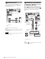
Connecting to your TV
This connection will use your TV’s speakers for sound. If you
use the SCART (EURO AV) cord in pattern A of “Step 3:
Connecting the Video Cords” (page 5), you do not have to
connect audio cords to your TV.
* The yellow plug is used for video signals (page 6).
z Hint
When connecting to a monaural TV, use a stereo-mono conversion cord
(not supplied). Connect the LINE 2 OUT (R-AUDIO-L) jacks to the
TV’s audio input jack.
Note
Do not connect the LINE 4 IN (R-AUDIO-L) jacks to your TV’s audio
output jacks at the same time.
Connecting to a stereo amplifier
(receiver) and 2 speakers/Connecting
to an MD deck or DAT deck
If your stereo amplifier (receiver) only has audio input jacks L
and R, use . If your amplifier (receiver) has a digital input
jack, or when connecting to an MD deck or DAT deck, use .
In this case, you can also connect the recorder directly to the MD
deck or DAT deck without using your stereo amplifier
(receiver).
z Hint
For connection , you can use the supplied audio/video cord instead
of using a separate stereo audio cord.
A
~
AC IN
LINE 2 OUT
S VIDEOVIDEOR-AUDIO-L
COMPONENT
VIDEO OUT
C
B
Y
C
R
LINE 4 IN
S VIDEOVIDEOR-AUDIO-L
LINE 1 - TV
AERIAL
IN
OUT
LINE 3/DECODER
DIGITAL OUT
PCM/DTS/MPEG/
DOLBY DIGITAL
COAXIAL
OPTICAL
LINE 2 OUT
S VIDEOVIDEOR-AUDIO-L
A
AUDIO
INPUT
L
R
VIDEO
DVD recorder
to LINE 2 OUT (R-AUDIO-L)
TV
(yellow)
(white)
(red)
(yellow)*
(white)
(red)
Audio/video cord (supplied)
: Signal flow
B
B-1
B-2
~
AC IN
LINE 2 OUT
S VIDEOVIDEOR-AUDIO-L
COMPONENT
VIDEO OUT
C
B
Y
C
R
LINE 4 IN
S VIDEOVIDEOR-AUDIO-L
LINE 1 - TV
AERIAL
IN
OUT
LINE 3/DECODER
DIGITAL OUT
PCM/DTS/MPEG/
DOLBY DIGITAL
COAXIAL
OPTICAL
DIGITAL OUT
PCM/DTS/MPEG/
DOLBY DIGITAL
COAXIAL
OPTICAL
LINE 2 OUT
S VIDEOVIDEOR-AUDIO-L
B-2 B-1
DVD recorder
Coaxial digital cord
(not supplied)
to DIGITAL OUT
(COAXIAL or OPTICAL)
or
to LINE 2 OUT
(R-AUDIO-L)
(white)(red)
Stereo audio
cord (not
supplied)
(white)(red)
to audio input
Stereo amplifier (receiver)
MD deck/DAT deck
[Speakers]
Front (L)
Front (R)
to coaxial or optical
digital input
Optical digital cord
(not supplied)
: Signal flow
B-1

9
Step 4: Connecting the Audio Cords
Basic Hookups and Settings
Connecting to an AV amplifier
(receiver) having a Dolby Surround (Pro
Logic) decoder and 3 to 6 speakers
If your AV amplifier (receiver) only has L and R audio input
jacks , use . If your amplifier (receiver) has a digital input
jack, use .
You can enjoy Dolby Surround effects only when playing Dolby
Surround audio or multi-channel audio (Dolby Digital) discs.
z Hint
For correct speaker location, refer to the operating instructions of the
connected components.
Note
When connecting 6 speakers, replace the monaural rear speaker with a
centre speaker, 2 rear speakers, and a subwoofer.
Connecting to an AV amplifier
(receiver) with a digital input jack and
6 speakers
If your AV amplifier (receiver) has a Dolby Digital, MPEG
audio, or DTS decoder and a digital input jack, use this
connection. Note that the surround sound effects of this recorder
cannot be used with this connection.
z Hint
For correct speaker location, refer to the operating instructions of the
connected components.
Note
After you have completed the connection, be sure to set “Dolby Digital”
to “Dolby Digital” and “DTS” to “On” under “Audio” in Easy Setup
(page 13). If your AV amplifier (receiver) has an MPEG audio decoder
function, set “MPEG” in “Audio” to “MPEG” (
see “AUDIO Settings”
in the separate booklet “Operating Instructions”). Otherwise, no sound
or a loud noise will come from your speakers.
C
C-1
C-2
~
AC IN
LINE 2 OUT
S VIDEOVIDEOR-AUDIO-L
COMPONENT
VIDEO OUT
C
B
Y
C
R
LINE 4 IN
S VIDEOVIDEOR-AUDIO-L
LINE 1 - TV
AERIAL
IN
OUT
LINE 3/DECODER
DIGITAL OUT
PCM/DTS/MPEG/
DOLBY DIGITAL
COAXIAL
OPTICAL
DIGITAL OUT
PCM/DTS/MPEG/
DOLBY DIGITAL
COAXIAL
OPTICAL
LINE 2 OUT
S VIDEOVIDEOR-AUDIO-L
C-1
C-2
DVD recorder
Coaxial digital cord
(not supplied)
to DIGITAL OUT
(COAXIAL or OPTICAL)
or
to LINE 2 OUT
(R-AUDIO-L)
(white)(red)
Stereo audio
cord (not
supplied)
(white)(red)
to audio input
to coaxial or optical
digital input
Optical digital cord
(not supplied)
[Speakers] [Speakers]
Rear (L) Rear (R)
Subwoofer
Centre
Rear (mono)
Front (L)
Front (R)
Amplifier (receiver)
with Dolby Surround
decoder
: Signal flow
D
~
AC IN
LINE 2 OUT
S VIDEOVIDEOR-AUDIO-L
COMPONENT
VIDEO OUT
C
B
Y
C
R
LINE 4 IN
S VIDEOVIDEOR-AUDIO-L
LINE 1 - TV
AERIAL
IN
OUT
LINE 3/DECODER
DIGITAL OUT
PCM/DTS/MPEG/
DOLBY DIGITAL
COAXIAL
OPTICAL
DIGITAL OUT
PCM/DTS/MPEG/
DOLBY DIGITAL
COAXIAL
OPTICAL
D
DVD recorder
to DIGITAL OUT
(COAXIAL or OPTICAL)
Coaxial digital cord
(not supplied)
Optical digital cord
(not supplied)
to coxial digital inputto optical digital input
[Speakers] [Speakers]
Rear (L)
Rear (R)
Subwoofer Front (L)
Front (R)
Centre
AV amplifier
(receiver) having a
decoder
: Signal flow
or

10
Step 5: Connecting the Mains Lead
Step 5: Connecting the
Mains Lead
Connect the supplied mains lead to the AC IN terminal of the
recorder. Then plug the recorder and TV mains leads (power
cords) into the mains. After you connect the mains lead, you
must wait for a short while before operating the recorder.
You can operate the recorder once the front panel display lights
up and the recorder enters standby mode.
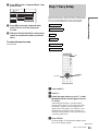
Step 6: Preparing the
Remote
You can control the recorder using the supplied remote. Insert
two R6 (size AA) batteries by matching the 3 and # ends on
the batteries to the markings inside the battery compartment.
When using the remote, point it at the remote sensor on the
recorder.
Notes
• Do not leave the remote in an extremely hot or humid place.
• Do not drop any foreign object into the remote casing, particularly
when replacing the batteries.
• Do not expose the remote sensor to direct sunlight or a lighting
apparatus. Doing so may cause a malfunction.
• If you do not use the remote for an extended period of time, remove the
batteries to avoid possible damage from battery leakage and corrosion.
If you have a Sony DVD player or more
than one Sony DVD recorder
If the supplied remote interferes with your other Sony DVD
recorder or player, set the command mode number for this
recorder and the supplied remote to one that differs from the
other Sony DVD recorder or player.
The default command mode setting for this recorder and the
supplied remote is DVD 3.
a Press SYSTEM MENU.
The System Menu appears.
b Press M/m to select “SETUP,” then press
ENTER.
c Press M/m to select “Options,” then press
ENTER.
~
AC IN
mains lead
to AC IN
SYSTEM
MENU
M/m, ENTER
COMMAND MODE
RETURN
SETUP
Settings
Video
Audio
Features
Options
Easy Setup
Channel Setting
Channel List
Clock
Language
Settings
Video
Audio
Features
Options
Easy Setup
Format Disc :
Bilingual Recording :
Dimmer :
Auto Display :
Command Mode :
Factory Setup
Selectable
Main
Bright
On
DVD3
SETUP

11
Step 7: Easy Setup
Basic Hookups and Settings
d Press M/m to select “Command Mode,” then
press ENTER.
e Press M/m to select the Command mode
(DVD1, DVD2, or DVD3), then press
ENTER.
f Slide the COMMAND MODE switch on the
remote so it matches the mode you selected
above.
To return to the previous step
Press RETURN.
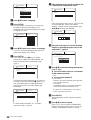
Step 7: Easy Setup
Follow the steps below to make the minimum number of basic
adjustments for using the recorder. If you do not complete Easy
Setup, it will appear each time you turn on your recorder.
You will make the settings below in the following order.
m
m
m
m
m
a Turn on the TV.
b Press [/1.
c Switch the input selector on your TV so that
the signal from the recorder appears on your
TV screen.
“Initial settings necessary to operate the DVD
recorder will be made. You can change them later
using Setup.” appears. If this message does not
appear, select “Easy Setup” from “SETUP” in the
System Menu to run Easy Setup. For details, see
“Settings and Adjustments” in the separate booklet
“Operating Instructions.”
d Press ENTER.
The Setup Display for selecting the language used in
the on-screen display appears.
Settings
Video
Audio
Features
Options
Easy Setup
Format Disc :
Bilingual Recording :
Dimmer :
Auto Display :
Command Mode :
Factory Setup
Selectable
Main
Bright
On
DVD3
SETUP
DVD1
DVD2
DVD3
OSD Language Setup
Tuner and Channel Setup
Clock Setup
TV Type Setup
Video Connection Setup
Audio Connection Setup
"/1
</M/m/,,
ENTER
RETURN
,continued

12
Step 7: Easy Setup
e Press M/m to select a language.
f Press ENTER.
The setup Display for selecting your country and
language for the tuner system appears. The
programme order will be set according to the country
or language you select.
g Press M/m to select your country or language.
If you live in a French speaking country that is not
listed on the display, select “ELSE.”
h Press ENTER.
If you made connection A (page 5) and the
connected TV complies with SMARTLINK, the
Preset Download function automatically starts
(page 6).
If the Preset Download function does not work or if
you made a connection other than A (page 5), the
Auto Tuner Preset function automatically starts
searching for all of the receivable channels and
presets them.
To set the channels manually, see “Presetting
channels manually” (page 16).
i After the download or search is complete, the
Clock function automatically starts.
If the current time or date is not set, “The clock was
not set automatically. Set the time and date
manually.” appears. Set the clock manually using
</M/m/,, and then press ENTER.
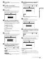
j Once the clock signal is received, the Setup
Display for selecting the aspect ratio of the
connected TV appears.
k Press M/m to select the setting that matches
your TV type.
◆ If you have a wide-screen TV or a 4:3 standard
TV with a wide-screen mode
•16:9
◆ If you have a 4:3 standard TV
• 4:3 Letter Box
Displays a wide picture with bands on the upper and
lower sections of the screen.
• 4:3 Pan Scan
Automatically displays a wide picture on the entire
screen and cuts off the sections that do not fit.
For details, see “VIDEO Settings” in the separate
booklet “Operating Instructions.”
l Press ENTER.
The Setup Display for the Component Out jacks
appears.
m Press M/m to select an option.
Select “On” if you are using the COMPONENT
VIDEO OUT jacks, or select “Off” if you are not
using the COMPONENT VIDEO OUT jacks.
OSD 1/9
Select the screen Language.
English
Français
Deutsch
Italiano
Español
EASY SETUP
EASY SETUP Tuner System 2/9
Select a country and
language.
L
N
NL
P
S
SF
UK
ELSE
– Français
– Dansk/Norsk
– Nederlands
– Português
– Svenska
– Suomi
– English
– English
EASY SETUP Preset Download 3/9
Loading data from TV.
Please wait.
Prog. 1
EASY SETUP Auto Tuner Preset 3/9
Searching for receivable channels.
Please wait.
Prog. 1
EASY SETUP Clock 4/9
Searching for clock data.
Please wait.
EASY SETUP Clock 4/9
The clock was not set automatically.
Set the time and date manually.
Sun 14 92100:2003
EASY SETUP TV Type 5/9
Select your TV screen type.
16 : 9
4 : 3 Letter Box
4 : 3 Pan Scan

13
Step 7: Easy Setup
Basic Hookups and Settings
n Press ENTER.
The Setup Display for the LINE 3/DECODER jack
appears.
o Press M/m to select an option.
Select “Yes” if you will connect a decoder to the
LINE 3/DECODER jack, or select “No” if you will
not connect a decoder.
p Press ENTER.
The Setup Display for selecting the type of video
signal output from the LINE1-TV jack appears.
q Press M/m to select the type of signal you
want to output from the LINE1-TV jack.
Note that if you select “On” in step 13, you cannot
select “RGB,” and that if you select “Yes” in step 15,
you cannot select “S Video.”
◆ To output Video signals
•Video
◆ To output S video signals
•S Video
◆ To output RGB signals
•RGB
If you select “S Video” or “RGB,” SMARTLINK
will be deactivated.
r Press ENTER.
The Setup Display for selecting the type of jack used
to connect to your amplifier (receiver) appears.
s Press M/m to select the type of jack (if any)
you are using to connect to an amplifier
(receiver), then press ENTER.
Choose the item that matches the audio connection
you selected on pages 8 to 9 ( through ).
• If you connect just a TV and nothing else, select “No,”
then go to step 23.
• Select “Yes: LINE 2 OUT (R-AUDIO-L),” then go to
step 23.
• Select “Yes: DIGITAL OUT.” The Setup Display for
“Dolby Digital” appears.
t Press M/m to select the type of Dolby Digital
signal you wish to send to your amplifier
(receiver).
Choose the signal that matches the audio connection
you selected on pages 8 to 9 ( through ).
•D-PCM
• Dolby Digital (only if the amplifier (receiver) has a
Dolby Digital decoder)
u Press ENTER.
The Setup Display for selecting the type of DTS
signal appears.
v Press M/m to select the type of DTS signal you
wish to send to your amplifier (receiver) and
press ENTER.
Choose the item that matches the audio connection
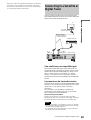
you selected on pages 8 to 9 ( through ).
•Off
• On (only if the amplifier (receiver) has a DTS decoder)
w Press ENTER when “Finish” appears.
Easy Setup is finished. All connections and setup
operations are complete.
To return to the previous step
Press RETURN.
z Hints
• If your AV amplifier (receiver) has an MPEG audio decoder, set
“MPEG” to “MPEG” (see “AUDIO Settings” in the separate booklet
“Operating Instructions”).
• If you want to run Easy Setup again, select “Easy Setup” from “Setup”
in the System Menu.
EASY SETUP Line1 Output 8/9
Select the Line1 output signal.
Video
S Video
RGB
EASY SETUP Audio Connection 9/9
Is this recorder connected to an amplifier (receiver)?
Select the type of jack you are using.
Yes : LINE2 OUT(R-AUDIO-L)
Yes : DIGITAL OUT
No
A D
A
B-1 C-1
B-2 C-2
D
B
D
EASY SETUP Audio Connection 9/9
Dolby Digital
D-PCM
Dolby Digital
B-2 C-2
D
EASY SETUP Audio Connection 9/9
DTS
On
Off
B
D
B-2 C-2
D
EASY SETUP
Easy Setup is finished
Finish

14
Setting the Clock
Advanced
Hookups and
Settings
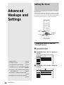
Setting the Clock
You must set the time and date on the recorder to use the timer
features properly.
The Auto Clock Set function works only if a station in your area
is broadcasting a time signal. If the Auto Clock Set function did
not set the clock correctly for your local area, try another station
for the Auto Clock Set function or set the clock manually.
Changing the station for the Auto
Clock Set function
a Press SYSTEM MENU.
The System Menu appears.
b Press M/m to select “SETUP,” then press
ENTER.
c Press M/m to select “Settings,” then press
ENTER.
SYSTEM
MENU
RETURN
</M/m/,,
ENTER
SETUP
Settings
Video
Audio
Features
Options
Easy Setup
Channel Setting
Channel List
Clock
Language
SETUP
Settings
Video
Audio
Features
Options
Easy Setup
Channel Setting
Channel List
Clock
Language
• Setting the Clock. . . . . . . . . . . . . . . . . page 14
• Presetting Channels . . . . . . . . . . . . . . page 16
• Changing/Disabling the Channels. . . . page 19
• Controlling Your TV or AV Amplifier (Receiver)
. . . . . . . . . . . . . . . . . . . . . . . . . . . . page 21
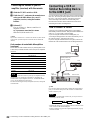
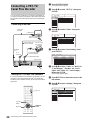
• Connecting a VCR or Similar Recording Device
to the LINE3 Jack. . . . . . . . . . . . . . page 22
• Connecting to a Satellite or Digital Tuner
. . . . . . . . . . . . . . . . . . . . . . . . . . . . page 23
• Connecting a PAY-TV/Canal Plus Decoder
. . . . . . . . . . . . . . . . . . . . . . . . . . . . page 24

15
Setting the Clock
Advanced Hookups and Settings
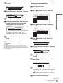
d Press M/m to select “Clock,” then press
ENTER.
e Press M/m to select “Auto Adjust,” then press
ENTER.
f Press M/m to select “On,” then press ,.
g Press M/m repeatedly until the programme
position of the station that carries a time
signal appears, then press ENTER.
If the recorder does not receive a time signal from
any station, “Auto Adjust” returns to “Off”
automatically and the menu for setting the clock
manually appears on the screen.
h Press SYSTEM MENU repeatedly to exit the
menu.
To return to the previous step
Press RETURN.
z Hint
If you set “Auto Adjust” to “On,” the Auto Clock Set function is
activated whenever the recorder is turned off. The time is adjusted
automatically by receiving the time signal from the station displayed in
the “Auto Adjust” row.
Setting the clock manually
a Press SYSTEM MENU.
The System Menu appears.
b Press M/m to select “SETUP,” then press
ENTER.
c Press M/m to select “Settings,” then press
ENTER.
d Press M/m to select “Clock,” then press
ENTER.
e Press M/m to select “Auto Adjust,” then press
ENTER.
f Press M/m to select “Off,” then press
ENTER.
g Press M/m to select “Present Time,” then
press ENTER.
h Press M/m to set the day, then press ,.
Set the month, year, hour, and minutes in sequence.
Press </, to select the item to be set, then press
M/m to set the numbers. The day of the week is set
automatically.
i Press ENTER to start the clock.
Settings - Clock
Auto Adjust : Off 1
Present Time : Sun 14. 9. 2003. 21:39
Settings - Clock
Auto Adjust : Off 1 ARD
Present Time : Sun 14. 9. 2003. 21:39
Off 1
Settings - Clock
Auto Adjust : Off 1 ARD
Present Time : Sun 14. 9. 2003. 21:39
On 1
SETUP
Settings
Video
Audio
Features
Options
Easy Setup
Channel Setting
Channel List
Clock
Language
SETUP
Settings
Video
Audio
Features
Options
Easy Setup
Channel Setting
Channel List
Clock
Language
Settings - Clock
Auto Adjust : Off 1
Present Time : Wed 1. 1. 2003. 00:00
Settings - Clock
Auto Adjust : Off 1 ARD
Present Time : Wed 1. 1. 2003. 00:00
Off 1
Clock - Present Time
Set the time and date manually.
00 00:
1 2003
Wed 1
,continued

16
Presetting Channels
j Press SYSTEM MENU repeatedly to exit the
menu.
To return to the previous step
Press RETURN.
z Hint
To change the numbers in step 8, press < to return to the item to be
changed, and select the numbers by pressing M/m.
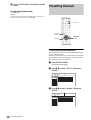
Presetting Channels
Presetting channels manually
If some channels could not be set using the Easy Setup function,
you can set them manually.
If there is no sound or if the picture is distorted, the wrong tuner
system may have been preset during Easy Setup. Set the correct
tuner system manually in the steps below.
a Press SYSTEM MENU.
The System Menu appears.
b Press M/m to select “SETUP,” then press
ENTER.
c Press M/m to select “Settings,” then press
ENTER.
SYSTEM
MENU
RETURN
PROG +/–
</M/m/,,
ENTER
SETUP
Settings
Video
Audio
Features
Options
Easy Setup
Channel Setting
Channel List
Clock
Language
Settings
Video
Audio
Features
Options
Easy Setup
Channel Setting
Channel List
Clock
Language
SETUP

17
Presetting Channels
Advanced Hookups and Settings
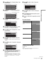
d Press M/m to select “Channel Setting,” then
press ENTER.
e Press PROG +/– to select the programme
position.
f Press M/m to select “System,” then press
ENTER.
g Press M/m to select an available TV system,
BG, DK, L, or I, then press ENTER.
h Press M/m to select “Normal/CATV,” then
press ENTER.
i Press M/m to select “Normal,” then press
ENTER.
To set CATV (Cable Television) channels, select
“CATV.”
j Press M/m to select “Channel Set,” then press
ENTER.
k Press M/m repeatedly until the channel you
want is displayed, then press ENTER.
The channels are scanned in the order shown in the
table below.
If you know the number of the channel you want,
press the number buttons. For example, for channel
5, first press “0” and then press “5.” Then press
ENTER.
l Press M/m to select “Audio,” then press
ENTER.
m Press M/m to select “NICAM,” then press
ENTER.
n To set another programme position, repeat
steps 5 through 13.
o Press SYSTEM MENU repeatedly to exit the
menu.
Receivable Channels
To return to the previous step
Press RETURN.
z Hint
If the sound is not clear when listening to NICAM broadcasts, set
“Audio” explained above to “Standard.”
Settings - Channel Setting Prog. 1
System :
Normal / CATV :
Channel Set :
Station Name :
Pay - TV / CANAL+ :
Audio :
BG
Normal
C3
AAB
Off
NICAM
Settings - Channel Setting Prog. 8
System :
Normal / CATV :
Channel Set :
Station Name :
Pay - TV / CANAL+ :
Audio :
BG
Normal
C2
CDE
Off
NICAM
Selected programme position
Settings - Channel Setting
Prog. 8
System :
Normal / CATV :
Channel Set :
Station Name :
Pay - TV / CANAL+ :
Audio :
BG
Normal
C1
ARD
On
NICAM
BG
DK
I
L
Settings - Channel Setting
Prog. 8
System :
Normal / CATV :
Channel Set :
Station Name :
Pay - TV / CANAL+ :
Audio :
BG
Normal
C1
CDE
Off
NICAM
Normal
CATV
Settings - Channel Setting Prog. 8
System :
Normal / CATV :
Channel Set :
Station Name :
Pay - TV / CANAL+ :
Audio :
BG
Normal
C1
CDE
Off
NICAM
C2
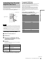
TV system Channel coverage
BG (West European
Countries, except those listed
below)
E2 - E12 VHF
Italia A – H VHF
E21 – E69 UHF
S1 – S20 CATV
S21 – S41 HYPER
S01 – S05 CATV
DK (East European Countries) R1 – R12 VHF
E21 – E69 UHF
S1 – S20 CATV
S21 – S41 HYPER
S01 – S05 CATV
L (France) F2 – F10 VHF
F21 – F69 UHF
B – Q CATV
S21 – S41 HYPER
I (Great Britain/Ireland) Ireland A – J VHF
South Africa 4 – 13 VHF
B21 – B69 UHF
S1 – S20 CATV
S21 – S41 HYPER
S01 – S05 CATV
Settings - Channel Setting Prog. 8
System :
Normal / CATV :
Channel Set :
Station Name :
Pay - TV / CANAL+ :
Audio :
BG
Normal
C2
CDE
Off
NICAM
NICAM
Standard
,continued

18
Presetting Channels
If the picture is not clear
If the Auto Fine Tuning (AFT) function does not effectively tune
the picture of a certain station, you will need to adjust the
pictures manually.
a Press PROG +/– or the number buttons to
select the programme position for which you
cannot obtain a clear picture.
b Press SYSTEM MENU.
The System Menu appears.
c Press M/m to select “SETUP,” then press
ENTER.
d Press M/m to select “Settings,” then press
ENTER.
e Press M/m to select “Channel Setting,” then
press ENTER.
f Press M/m to select “AFT,” then press
ENTER.
g Press M/m to select “Off,” then press
ENTER.
The fine tuning bar appears.
h Press </, to get a clearer picture, then
press ENTER.
i Press SYSTEM MENU repeatedly to exit the
menu.
To return to the previous step
Press RETURN.
Note
While adjusting the picture, the display may become difficult to read due
to interference from the picture being received.
Settings
Video
Audio
Features
Options
Easy Setup
Channel Setting
Channel List
Clock
Language
SETUP
Settings
Video
Audio
Features
Options
Easy Setup
Channel Setting
Channel List
Clock
Language
SETUP
Settings - Channel Setting Prog. 8
System :
Normal / CATV :
Channel Set :
Station Name :
Pay - TV / CANAL+ :
Audio :
BG
Normal
C2
CDE
Off
NICAM
Settings - Channel Setting
Prog. 8
Normal / CATV :
Channel Set :
Station Name :
Pay - TV / CANAL+ :
Audio :
AFT :
Normal
C2
CDE
Off
NICAM
On
On
Off
Fine Tuning
Prog. 8

19
Changing/Disabling the Channels
Advanced Hookups and Settings
Changing/Disabling the
Channels
After setting the channels, you can change the programme
positions. If any programme positions are unused or contain
unwanted channels, you can disable them.
You can also change the station names. If the station names are
not displayed, you can enter them manually.
Changing or disabling programme
positions
a Press SYSTEM MENU.
The System Menu appears.
b Press M/m to select “SETUP,” then press
ENTER.
c Press M/m to select “Settings,” then press
ENTER.
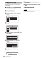
d Press M/m to select “Channel List,” then
press ENTER.
e Press M/m to select the row containing the
programme position you want to change or
disable.
◆ To change
Press ENTER and go to step 6.
◆ To disable
Press CLEAR and go to step 8. The disabled
positions will be skipped when you press the
PROG +/– buttons.
To display other pages for programme positions 7 to
99, press M/m repeatedly.
f Press M/m until the selected channel row
moves to the desired programme position.
The selected channel is inserted at the new
programme position.
g Press ENTER to confirm the setting.
h To change or disable the programme position
of another station, repeat steps 5 through 8.
i Press SYSTEM MENU repeatedly to exit the
menu.
To return to the previous step
Press RETURN.
Note
Be sure to select the programme position you want to disable correctly.
If you disable a programme position by mistake, you need to reset that
channel manually (page 16).
CLEAR
SYSTEM
MENU
</M/m/,,
ENTER
RETURN
PROG +/–
Settings
Video
Audio
Features
Options
Easy Setup
Channel Setting
Channel List
Clock
Language
SETUP
Settings
Video
Audio
Features
Options
Easy Setup
Channel Setting
Channel List
Clock
Language
SETUP
Settings - Channel List
Prog
1
2
3
4
5
6
Channel
Name
AAB
FGH
PQR
C3
C5
C12
C21
C23
C24
Settings - Channel List
Prog
1
2
3
4
5
6
Channel Name
AAB
FGH
PQR
C3
C12
C21
C5
C23
C24
,continued

20
Changing/Disabling the Channels
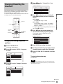
Changing the station names
You can change or enter a station name (up to 5 characters). The
recorder must receive channel information (for instance,
SMARTLINK information) for station names to appear
automatically.
a Press SYSTEM MENU.
The System Menu appears.
b Press M/m to select “SETUP,” then press
ENTER.
c Press M/m to select “Settings,” then press
ENTER.
d Press M/m to select “Channel Setting,” then
press ENTER.
e Press PROG +/– to select the programme
position for which you want to change or
enter a station name.
f Press M/m to select “Station Name,” then
press ENTER.
The display for entering characters appears.
◆ To enter a character
A Press </M/m/, to move the cursor to the
right of the screen and select “A”(upper case),
“a”(lower case), or “Symbol,” then press
ENTER.
B Press </M/m/, to select the character you
want to enter, then press ENTER.
The selected character appears at the top of the
display.
C Repeat steps 1 and 2 to enter all of the
characters for the station name.
◆ To erase a character
A Press </M/m/, to move the cursor to the
input row.
B Press </, to move the cursor to the right of
the character you want to erase.
C Press </M/m/, to select “Back,” then press
ENTER.
◆ To insert a character
A Press </M/m/, to move the cursor to the
input row.
B Press </M/m/, to move the cursor to the
right of the point where you want to insert a
character.
C Press </M/m/, to select the character you
want to insert, then press ENTER.
◆ To erase all of the characters
Press </M/m/, to select “Clear All,” then
press ENTER.
For details, see “Guide to Displays” in the separate
booklet “Operating Instructions”.
g Press </M/m/, to select “Finish,” then
press ENTER.
h Press SYSTEM MENU repeatedly to exit the
menu.
To return to the previous step
Press RETURN.
Settings
Video
Audio
Features
Options
Easy Setup
Channel Setting
Channel List
Clock
Language
SETUP
Settings
Video
Audio
Features
Options
Easy Setup
Channel Setting
Channel List
Clock
Language
SETUP
Settings - Channel Setting Prog. 1
System :
Normal / CATV :
Channel Set :
Station Name :
Pay - TV / CANAL+ :
Audio :
BG
Normal
C3
AAB
Off
NICAM
AAB
"A"
"a"
Symbol
Cancel
Finish
Space
Clear All
Back
,. - 1
BA C 2
ED F 3
HG I 4
KJ L5
1
2
3
4
5
NM O 6
QP R S
UT V 8
XW Y Z
7
9
0
6
7
8
9
0
Input Station Name:
Page is loading ...
Page is loading ...
Page is loading ...
Page is loading ...
Page is loading ...
Page is loading ...
Page is loading ...
Page is loading ...
-
 1
1
-
 2
2
-
 3
3
-
 4
4
-
 5
5
-
 6
6
-
 7
7
-
 8
8
-
 9
9
-
 10
10
-
 11
11
-
 12
12
-
 13
13
-
 14
14
-
 15
15
-
 16
16
-
 17
17
-
 18
18
-
 19
19
-
 20
20
-
 21
21
-
 22
22
-
 23
23
-
 24
24
-
 25
25
-
 26
26
-
 27
27
-
 28
28


Sony RDR-GX7 Operating instructions
- Category
- DVD players
- Type
- Operating instructions
Ask a question and I''ll find the answer in the document
Finding information in a document is now easier with AI