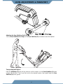
Exerpeutic 1317.5-101016 is an elliptical trainer designed for home use. It features magnetic resistance system for smooth and quiet workouts. The console tracks time, distance, speed, calories burned, and pulse. The stride length is adjustable to accommodate users of different heights. The pedals are equipped with adjustable straps to ensure a secure fit. The machine has a sturdy steel frame and can support a maximum weight of 270 lbs. It comes with a water bottle holder for convenience. Assembly is required and the necessary tools are included.
Exerpeutic 1317.5-101016 is an elliptical trainer designed for home use. It features magnetic resistance system for smooth and quiet workouts. The console tracks time, distance, speed, calories burned, and pulse. The stride length is adjustable to accommodate users of different heights. The pedals are equipped with adjustable straps to ensure a secure fit. The machine has a sturdy steel frame and can support a maximum weight of 270 lbs. It comes with a water bottle holder for convenience. Assembly is required and the necessary tools are included.


-
 1
1
-
 2
2
-
 3
3
-
 4
4
-
 5
5
-
 6
6
-
 7
7
-
 8
8
-
 9
9
-
 10
10
-
 11
11
-
 12
12
-
 13
13
-
 14
14
-
 15
15
-
 16
16
-
 17
17
-
 18
18
-
 19
19
-
 20
20
-
 21
21
-
 22
22
-
 23
23
-
 24
24
-
 25
25
-
 26
26
-
 27
27
-
 28
28
-
 29
29
-
 30
30
-
 31
31
-
 32
32


Exerpeutic 1317 Owner's manual
- Type
- Owner's manual
- This manual is also suitable for
Exerpeutic 1317.5-101016 is an elliptical trainer designed for home use. It features magnetic resistance system for smooth and quiet workouts. The console tracks time, distance, speed, calories burned, and pulse. The stride length is adjustable to accommodate users of different heights. The pedals are equipped with adjustable straps to ensure a secure fit. The machine has a sturdy steel frame and can support a maximum weight of 270 lbs. It comes with a water bottle holder for convenience. Assembly is required and the necessary tools are included.
Ask a question and I''ll find the answer in the document
Finding information in a document is now easier with AI
Related papers
-
Exerpeutic 1317 Owner's manual
-
-
-
-
-
-
-
-
-
Other documents
-
 Walker Edison Furniture Company HDHL30BR Operating instructions
-
 Walker Edison Furniture Company HDHL18WB Operating instructions
-
 Walker Edison Furniture Company HDHL18BL Operating instructions
-
 Cambridge Casual HD-240275A Installation guide
-
Ironman Fitness 6336 Owner's manual
-
 Walker Edison Furniture Company HD48UBGLAG Installation guide
-
Fitness Reality 2338 Owner's manual
-
VEVOR LTFSYHS3BDXSFST01V0 User manual
-
 Cambridge Casual HD-370218T User manual
-


