
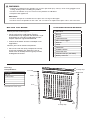
Aluminum Fence Kit
BOM-34109932
Read all instructions prior to installing product.
Refer to manufacturers safety instructions when operating any tools.
To register your product, please visit:
barretteoutdoorliving.com
INSTALLATION INSTRUCTIONS
• English
................................................................................
1
• Français
..............................................................................
9
• Español
.............................................................................
17

2
Post Kits
String
Stakes
Tape Measure
Post Hole Digger
Shovel
Level
Hacksaw
Rubber Mallet
Concrete Mix
Gravel/Filler (6" per hole)
Safety Glasses
TOOLS/MATERIALS NEEDED:
BEFORE YOU BEGIN:
Check your local zoning laws.
• Local zoning laws and Home Owners
Associations may regulate the location, style
and height of your fence and gate or even
require a permit signoff beforehand.
• Check local codes for frost line depth and
regulations.
Contact your local utilities companies.
• You must have the utility companies clearly
mark your property for electrical, gas or
water lines to avoid puncturing any unseen
underground utilities.
WARNING:
• Improper installation of this product can result in personal injury. Always wear safety goggles when
cutting, drilling and assembling the product.
• Incorrect installation may cause harm to the product or individual.
• Not pool code approved
NOTICE:
• DO NOT attempt to assemble the kit if parts are missing or damaged.
• DO NOT return the product to the store. For assistance or replacement parts call: 1-800-336-2383.
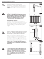
Post
Punched
Holes
Post Top
Top Rail
Middle Rail
Bottom
Rail
Pickets
Locking Strip
Punched
Bottom
Locking Strip
Fencing
Components:
Description
Top Rail
Locking Strips
Middle Rail*
Bottom Rail
Pickets
#8 x 1" Self-Tapping Screws
*Included with certain styles.

3
1.
2.
3.
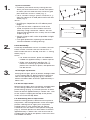
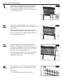
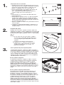
Layout installation:
• Establish your fence line by staking out the
areas you wish to enclose. Locate each point
in which you will need an end, corner or gate
post and mark it with a stake (Fig. 1).
• For 6' sections using 2" posts: measure 72
3
⁄
3
⁄
3
4
⁄4⁄
"
from the center of an end point and mark with
stake (Fig. 2).
NOTE:
• Installing on sloped terrain will reduce panel
length.
• If you are left with a space less than a full
panel, the panel can be cut down to t the
space by using a hacksaw. “Notch” the cut
ends of the horizontal rails so they will sit inside
of post (Fig. 3).
• Attach string to each stake to provide straight
guide lines.
• Plan gate placement, opening and hardware
clearance before installing fencing.
Fig. 1
Fig. 2
For 6' sections using
2" posts
2" posts
72
3
⁄
3
⁄
3
4
⁄4⁄
"
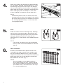
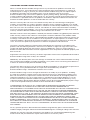
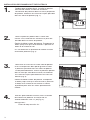
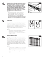
Panel Assembly:
Place top and bottom rails on a smooth, at and
clean surface. Position the rails so that the "J"
hook inside the rails is on top, with the "J" facing
down (Fig. 3).
NOTE:
• For three-rail fences, place the additional
middle rail approximately 2" below top rail.
• Make sure to properly position the "J"
hooks as shown (Fig. 3) otherwise the
pickets will not lock in place, and panel will
not be secure.
For Straight Top Panels:
Moving left to right, push all pickets through holes
in rails except top rail, being careful to have the
hole in each picket facing up (Fig. 4). Position
pickets to allow holes to remain approximately 2"
below rails.
For Picket Top Panels:
Moving left to right, push all pickets through holes
in rails, being careful to have the hole in each
picket facing up (Fig. 4). Position pickets to allow
holes to remain approximately 2" below rails. Due
to the size of crimping on the top of the picket,
insert rails from the top down.
For Alternating Picket Top Panels:
Before inserting pickets, determine the layout of
the pickets, alternating between small and larger
pickets. Moving left to right, push all pickets
through holes in rails except top rail, being
careful to have the hole in each picket facing up
(Fig. 4). Position pickets to allow holes to remain
approximately 2" below rails. Due to the size of
crimping on the top of the picket, insert rails from
the middle rail down.
Fig. 4
Holes
Holes
Fig. 4
Fig. 4
Fig. 3
Hook
Hook
Notch
Notch
Rails

4
5.
6.
4.
Locked
Fig. 6
Side Views of Rails
Side Views of Rails
Side Views of Rails
Side Views of Rails
Side Views of Rails
Side Views of Rails
Side Views of Rails
Side Views of Rails
Side Views of Rails
Side Views of Rails
Side Views of Rails
Side Views of Rails
Side Views of Rails
Side Views of Rails
and Locking Stripsand Locking Strips
Fig. 7
Fig. 4
Hole
Hole
ArrowArrow
BumpBump
Fig. 5
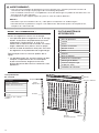
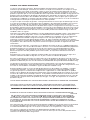
Make sure arrows on locking strip point towards
the rail above. Starting with the bottom rail, take
one locking strip, place and snap in the bumps
from the locking strip into the holes of the picket.
Move from left to right, using your thumb to push
down and tightly lock the bumps in each hole.
(Fig. 5). Repeat this process for the other rails.
NOTE:
If the fence panels were cut shorter, then the
locking strip will have extra length at the end of
the install. Use scissors or a knife to cut excess
off, leaving approximately 2" of the strip after
last engaged bump.
Rails
:
Slide rails down over the locking strips. Starting
from the left and moving right, gently place the
rail over the locking strip (Fig. 6). Run your hand
along the bottom of the rails. If you feel the
locking strip, it is not secure. You should only feel
the rail.
NOTE:
For a three-rail panel, start with the bottom
rail rst, then secure the middle rail, then the
top rail.
Lock in Pickets:
Stand up assembled fence panel section and
starting at one end of panel, place hands rmly
on rails, and push down until a "snap" is heard.
Repeat this process for the middle and end of the
panel with each rail. All the pickets should now
be locked into the rails (Fig. 7).
NOTE:
You may need to use a rubber mallet to
assist with locking the rails – gently tap the
rails with the mallet until the rails are secure
(an audible"snap" will indicate that the strip
is in the locked position).

5
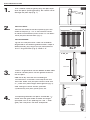
1.
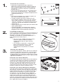
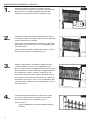
Use a rubber mallet to gently drive the post tops
onto the posts (sold separately). Be careful not to
damage the post top (Fig. 1).
POST INSTALLATION
The opening between the posts should be 1
1
⁄
1
⁄
1
2
⁄2⁄
"
wider than the gate width to allow for hinges.
(Example: Use a 48" opening for a 46
1
⁄
1
⁄
1
2
⁄2⁄
" wide
gate.) Be sure posts are level and plumb.
3.
4.
2.
Fig. 1
Fig. 2
Example:Example:
Frost Line
Gravel/
Filler
6"
6"
X+Y
Y
X
Fig. 3
Fig. 4
Post
Concrete
Gravel/Filler
Post Location:
Measure the width of the fence panel (X) plus the
width of the post (Y). This is the common center-
to-center measurement (unless there is a cut-down
panel) for post hole location (Fig. 2).
Post Installation:
Dig the rst two post holes. Hole size should be
dug based on the following determination: Depth is
determined by your local frost line measurements
plus 6" for gravel/ ller (Fig. 3). Width is 6"
Insert 6" of gravel/ ller into the bottom of both holes
and then set both posts into the ground and level
the rst post.
Add wet or dry concrete mix according to
manufacturer’s instructions to the top of the rst
post hole. Make sure your post remains level with
3
1
⁄
1
⁄
1
2
⁄2⁄
" more than panel height above ground (Fig. 4).
After setting rst fence section, proceed
systematically with post, panel, post, etc.

6
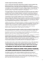
4.
1.
2.
3.
As the post is setting up, install the rst fence
panel. Insert the horizontal rails from the panel
into the punched holes from the previously
installed post. Place the rails as far into the post
as they will go (Fig. 1).
PANEL / POST INSTALLATION
Fig. 1
Fig. 2
Place the next required post into the dug hole,
and slide the post onto the rails of the panel as far
as possible.
Pour concrete around that post and tamp down,
leaving concrete about 2" from ground level.
You now have one fence panel upright between
two installed posts (Fig. 2).
Repeat by digging next hole and lling with 6"
of gravel. Then insert the next panel into the
previously installed post. Place the next post into
the dug hole and slide the post onto the rails of
the panel as far as possible (Fig. 3).
Pour concrete around that post and tamp down,
leaving concrete about 2" from ground level.
Repeat until end of line.
Fig. 3
Top view of post
Rail
Rail
Post
Fig. 4
After concrete has set, fasten the fence section
to the posts using #8 x 1" self-tapping screws
(Fig. 4).
IMPORTANT:
Be careful not to over-tighten screws.

7
What is covered: Barrette Outdoor Living warrants vinyl and aluminum products to include; vinyl
and aluminum fence, vinyl and aluminum railing and plastic lattice against defects in materials or
workmanship for as long as you own your home. Barrette Outdoor Living will at its option replace
the product in question with new product of the same or equivalent value at no charge.
Barrette Outdoor Living warrants these products against peeling, aking, splintering, corrosion,
rusting or abnormal discoloration under normal use. This warranty extends to the original purchaser
or transferee as speci ed herein on the products noted above. Separate and distinct warranties for
hardware and other products are not covered under this warranty.
What this warranty does not cover: This limited warranty does not cover damage resulting from
accident, unreasonable use, neglect, alteration, improper service, improper installation, acts of God
or any other causes not arising out of defects in materials or workmanship. Additionally, this warranty
does not cover costs of installation, removal, reinstallation or surface mold and mildew created by
excessive environmental conditions. Any service or repair provided outside the scope of this limited
warranty shall be at Barrette Outdoor Living’s rate and terms then in effect.
What do we do to correct the problems? Should your Barrette Outdoor Living product prove defective
under warranty, reference the website or call the phone number listed below. Your problem will be
assigned a tracking number and an authorized Barrette Outdoor Living representative will contact you
to arrange a convenient time to schedule an onsite inspection, or request pictures, if need be. If after
inspection product is deemed to be manufacturer defect we will make arrangements to rectify the
issue. You must have proof of your purchase in order for the problem to be corrected.
Transferee Coverage: Warranty coverage will be extended to one transferee on the above listed
products with the following limitations. Transferee must obtain an original or copy of the initial sales
receipt (with proof of date) from the previous owner(s). Additionally, if fence is purchased from a
builder or installer, documentation must be supplied that names the product installed on property and
date of transfer.
Registration: To activate this warranty, the online registration card must be completed and returned to
Barrette Outdoor Living within 30 days of installation.
Additionally, this Warranty does not cover damage associated with surface mold and mildew resulting
from environmental conditions including air pollution, or any other causes not arising out of defects in
materials or workmanship by Barrette Outdoor Living.
This Warranty does not cover costs of removal or disposal of product, or reinstallation of replacement
product. Any service provided outside the scope of this limited Warranty shall be at
Barrette Outdoor Living’s standard rate and terms then in effect.
Barrette Outdoor Living reserves the right to discontinue or modify any of its products, including
the color of its products, without notice to the homeowner/consumer, and Barrette Outdoor Living
does not warrant that any replacement material will match or be identical to the original product as
replacement products may vary in color or gloss in comparison to the original product as a result
of normal weathering. If Barrette Outdoor Living replaces any material under this Warranty, it may
substitute products designated by Barrette Outdoor Living to be of comparable quality or price range
in the event the product initially installed has been discontinued or modi ed.
THIS WARRANTY IS IN LIEU OF ALL CONDITIONS OR WARRANTIES, EXPRESS OR IMPLIED,
INCLUDING BUT NOT LIMITED TO ANY IMPLIED CONDITIONS OR WARRANTIES OF
MERCHANTABILITY OR FITNESS FOR A PARTICULAR PURPOSE ON THE PART OF
BARRETTE
OR
ITS LICENSORS, SOME STATES DO NOT ALLOW THE EXCLUSIONS OF IMPLIED WARRANTIES
OR LIMITATIONS OF HOW LONG AN IMPLIED WARRANTY LASTS, SO THE ABOVE LIMITATIONS
MAY NOT APPLY TO YOU. IF THE PRODUCT IS DEFECTIVE PER THE ABOVE COVERAGES, YOUR
SOLE AND EXCLUSIVE REMEDY SHALL BE REPAIR OR REPLACEMENT AS PROVIDED ABOVE.
BARRETTE AND ITS LICENSORS SHALL NOT BE LIABLE FOR ANY DAMAGES, LOSS OF USE,
LOSS OF PROFITS OR INTERRUPTION OF BUSINESS WHETHER SUCH ALLEGED DAMAGES ARE
BASED IN WARRANTY, TORT, CONTRACT, OR INDEMNITY. SOME STATES DO NOT ALLOW THE
EXCLUSION OF LIMITATIONS OF INCIDENTAL OR CONSEQUENTIAL DAMAGES, SO TH
E ABOVE
LIMITATIONS MAY NOT APPLY TO YOU. THIS WARRANTY IS VALID ONLY IN THE UNITED STATES
AND CANADA.
For any speci c questions about the Barrette Outdoor Living Warranty please contact Barrette
Outdoor Living by visiting our website www.barretteoutdoorliving.com, emailing or calling 1-800-336-2383.
To begin your warranty coverage and register your product visit: www.barretteoutdoorliving.com.
Retain manual and your dated sales slip for future reference or warranty claims.
Transferable Limited Lifetime Warranty
Page is loading ...
Page is loading ...
Page is loading ...
Page is loading ...
Page is loading ...
Page is loading ...
Page is loading ...
Page is loading ...
Page is loading ...
Page is loading ...
Page is loading ...
Page is loading ...
Page is loading ...
Page is loading ...
Page is loading ...
Page is loading ...

BARRETTE OUTDOOR LIVING
7830 FREEWAY CIRCLE
MIDDLEBURG HEIGHTS, OHIO 44130
TEL: (
800) 336-2383
WWW.BARRETTEOUTDOORLIVING.COM
-
 1
1
-
 2
2
-
 3
3
-
 4
4
-
 5
5
-
 6
6
-
 7
7
-
 8
8
-
 9
9
-
 10
10
-
 11
11
-
 12
12
-
 13
13
-
 14
14
-
 15
15
-
 16
16
-
 17
17
-
 18
18
-
 19
19
-
 20
20
-
 21
21
-
 22
22
-
 23
23
-
 24
24


YardSmart 73017842 Installation guide
- Type
- Installation guide
Ask a question and I''ll find the answer in the document
Finding information in a document is now easier with AI
in other languages
- français: YardSmart 73017842 Guide d'installation
- español: YardSmart 73017842 Guía de instalación
Other documents
-
Freedom 73008701 Installation guide
-
Weatherables WTR-THDVA42-S6 Operating instructions
-
-
Freedom 73024661 Installation guide
-
Barrette Outdoor Living 73014887 Operating instructions
-
 TuffBilt 73009470 Installation guide
-
-
-
Barrette Outdoor Living 73012194 Operating instructions
-
