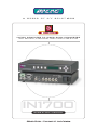
Extron IN1700 is a computer video scan converter that accepts computer video signals at resolutions of up to 1280 x 1024 and converts them to NTSC or PAL. It features a variety of output signal formats, flexible control options, and exceptional output image quality, making it an excellent choice for presentation facilities, multi-media and video production suites, teleconferencing centers, and other sites / applications requiring a high-performance scan converter.
Extron IN1700 is a computer video scan converter that accepts computer video signals at resolutions of up to 1280 x 1024 and converts them to NTSC or PAL. It features a variety of output signal formats, flexible control options, and exceptional output image quality, making it an excellent choice for presentation facilities, multi-media and video production suites, teleconferencing centers, and other sites / applications requiring a high-performance scan converter.


-
 1
1
-
 2
2
-
 3
3
-
 4
4
-
 5
5
-
 6
6
-
 7
7
-
 8
8
-
 9
9
-
 10
10
-
 11
11
-
 12
12
-
 13
13
-
 14
14
-
 15
15
-
 16
16
-
 17
17
-
 18
18


Extron IN1700 is a computer video scan converter that accepts computer video signals at resolutions of up to 1280 x 1024 and converts them to NTSC or PAL. It features a variety of output signal formats, flexible control options, and exceptional output image quality, making it an excellent choice for presentation facilities, multi-media and video production suites, teleconferencing centers, and other sites / applications requiring a high-performance scan converter.
Ask a question and I''ll find the answer in the document
Finding information in a document is now easier with AI
Related papers
Other documents
-
Epson Monitor-20" User manual
-
CYP SY-PT385A User manual
-
BakkerElkhuizen BNEEVOII Datasheet
-
CYP CPT-387 Operating instructions
-
 Vigatec MGVC 1280 Operating instructions
-
Extron electronic Super Emotia II User manual
-
-
GrandTec PC to TV EZ User manual
-
 S&S Research VM4HD Installation and User Manual
-

