
Bathroom Exhaust Fan
Installation and Operation Instructions
Please read all instructions before installing and operating.
All wiring and installation must be in accordance with CEC, NEC and local electrical codes.
READ AND SAVE THESE INSTRUCTIONS
HushTone

2 Bathroom Exhaust Fan Installation- English

3Bathroom Exhaust Fan Installation - English
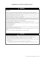
IMPORTANT SAFETY INSTRUCTIONS
• Do not use for cooking ventilation.
• For general ventilating use only. Do not use to exhaust hazardous or explosive materials and vapors.
• is product is designed for installation in ceilings up to a 12/12 pitch (45 degree angle). Duct connector must
point up. is product can be installed in a wall if mounted 8 feet or more above the oor.
• To avoid motor bearing damage and noisy and/or unbalanced impellers, keep drywall spray, construction dust,
etc. o power unit.
• Please read specication label on product for further information and requirements.
*e manual in electronic format can be download from our company web, or obtained from our dealer.
TO REDUCE THE RISK OF FIRE, ELECTRIC SHOCK, OR INJURY TO PERSONS, OBSERVE THE
FOLLOWING:
a). Use this unit only in the manner intended by the manufacturer. If you have questions, contact the manufacturer.
b). Before servicing or cleaning unit, switch power o at service panel and lock the service disconnecting means to prevent
power from being switching on accidentally. When the service disconnecting means cannot be locked, securely fasten
a prominent warning device, such as a tag, to the service panel.
c). Installation work and electrical wiring must be done by a qualied person(s) in accordance with all applicable codes and
standards, including re-rated construction codes and standards.
d). Sucient air is needed for proper combustion and exhausting of gases through the ue (chimney) of fuel burning equip-
ment to prevent backdraing. Follow the heating equipment manufacturer’s guideline and safety standards such as those
published by the National Fire Protection Association (NFPA), and the American Society for Heating, Refrigeration and
Air Conditioning Engineers (ASHRAE), and the local code authorities.
e). When cutting or drilling into wall or ceiling, do not damage electrical wiring and other hidden utilities.
f ). Ducted fans must always be vented to the outdoors.
g). Acceptable for use over a tub or shower when connected to a GFCI (Ground Fault Circuit Interrupter) - protected branch
circuit (ceiling installation only).
h).is unit must be grounded.
i). Not for use in kitchens.
j). To reduce risk of re and to properly exhaust air, be sure to duct air outside – Do not vent exhaust air into spaces within
walls or ceilings or into attics, crawl spaces, or garages.
k).WARNING: To Reduce e Risk Of Fire Or Electric Shock, Do Not Use is Fan With Any Solid-State Speed Control
Device.
l). e fan must not be installed in a ceiling thermally insulated to a value greater R40.
WARNING
CAUTION

4 Bathroom Exhaust Fan Installation- English
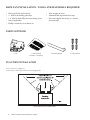
PLAN THE INSTALLATION
PARTS SUPPLIED
4 × Mounting Bracket 4 × Flange Screws1 × Grille Assembly
(Includes 2 × Grill Spring)
1. Do not use in a cooking area.
2. Two ways to connect ductwork to a factory-shipped unit.
DO NOT MOUNT OVER COOKING AREA
• Electrical drill or ratchet driver
• ½” drill bit for drilling pilot holes
• 1 ¼” drill bit for drilling electrical wiring access
hole (if applicable)
• Phillips screwdriver #2 or driver bit
• Wire stripper or cutter
• Aluminum foil tape and/or duct tape
• Electrical supplies for wiring (i.e. marrets,
electrical tape)
BATH FAN INSTALLATION - TOOLS AND MATERIALS REQUIRED
1 × Fan

5Bathroom Exhaust Fan Installation - English
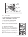
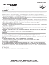
ROOF CAP*
(with built-in
damper)
ROUND
DUCT*
WALL CAP*
(with built-in
damper)
*
Purchase
separately
POWER
CABLE*
INSULATION*
(Place around and
over Fan Housing.)
Seal gaps
around
Housing.
FAN
HOUSING
ROUND
ELBOW(S) *
Seal duct
joints with
tape.
Keep duct
runs short
ROOF EXHAUST OR SIDE WALL EXHAUST
2. THREE TYPES OF TYPICAL MOUNTING
a) For housing mounted to I-joists (Begin at “FOR JOIST OR I-JOIST MOUNTING” )
b) For housing mounted to joists (Begin at “FOR HANGER BARS MOUNTING” )
c) For housing mounted to truss (Begin at “FOR TRUSS MOUNTING” )
Note: For best performance, use the shortest, straightest duct routing possible and avoid installing with
smaller ducts than suggested.
INSTALLATION STEPS
1. REMOVE PACKAGING AND SWITCH OFF POWER
FOR JOIST OR I-JOIST MOUNTING
Step 1: Hold the housing so that it is in contact with the bottom of the joist. Attach the
housing with four (4) screws to the joist through the holes in each mounting ange.
FOR HANGER BARS MOUNTING
Step 1: Sliding hanger bars have been provided, which allow the housing to be
positioned accurately anywhere between the framing. e bars span up to 24 inches
and can be used on all types of framing: I-joist, standard joist, and truss construction.
Slide hanger bars onto housing and adjust as needed to t between framing.
Step 2: Extend the hanger bars to the width of the framing. Position the ventilator
with the hanger bar tabs wrapped around the bottom edge of the framing, holding
the ventilator in place.
Step 3: Secure hanger bars to framing using one screw on each end of hanger bar. Select
a proper hole and secure the hanger bars together using the ange screws(provided).
HANGER
BAR
NAIL
SCREW

6 Bathroom Exhaust Fan Installation- English
Step 1: Snap the damper/duct connector onto the fan housing. e connector must
be ush with the top of the housing, and the damper ap should fall closed.
Optional: Insulated exible duct is recommended for the quietest possible installation.
If rigid duct is used, a short (1-3 feet) section of insulated exible duct will ensure
quiet operation.
DUCT
3. INSTALL ROUND DUCTWORK
Step 1: Connect the round ductwork (not included) to the damper/duct connector,
and run the ductwork to a roof or wall cap (not included).
Step 2: Using aluminum tape (not included), secure all the ductwork connections so
that they are air tight.
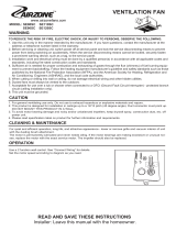
4. CONNECT ELECTRICAL WIRING
FAN
Wire
Panel
UNIT
BLACK (BLK)
SWITCH BOX
FAN
power supply
120V AC
GROUND (GRD)
WHITE(WHT)
fan
receptacle
• Run 120 V AC house wiring to the location of the fan. Use only UL-approved connectors (not included) to attach the house wiring to the wiring
plate. Refer to the wiring diagram, and connect the wires as shown.
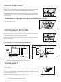
FOR TRUSS MOUNTING
* FOR MODEL CB50, PLEASE READ ADDITIONAL STEPS
Snap-in ans secure housing.
INSTALL GRILLE
Step 1: Install ceiling material to complete the ceiling construction. en, cut around
the fan housing.
Step 2: To attach the grille assembly to the fan housing, pinch the grille springs on
the sides of the grille assembly, and position the grille into the housing with the grille
springs in the appropriate slots.
Step 3: Push the grille assembly towards the ceiling to secure.

7Bathroom Exhaust Fan Installation - English
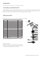
SERVICE PARTS
1
4
5
d
e
a
2
3
b
c
6
8
7
9
9
10
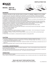
PART PART NAME Qty.
1 GRILLE 1
2 SPRING 2
3 MOTOR ASSEMBLY 1
4 MOTOR 1
5 BLOWER WHEEL 1
6 WIRE PANEL ASSEMBLY 1
7 WIRE COVER 1
8 HOUSING 1
9 HANGER BARS 4
10 DUCT CONNECTOR 1
a NUTS 4
b GROMMETS 4
c MOTOR BRACKETS 1
d MOTOR MOUNTING PLATE 4
e SCREWS 1
Replacement installation:
Remove the screw (part c), then take out the motor plate (part 3) from
the housing (part 8) by pushing down the rib in the plate while pulling
out on the side of the housing. Replace the broken parts.
WARNING: Ensure that the fan is switched o from the supply mains before replacing.
* Blower Assembly includes part 5, 4, d, 3, c, b, a.
CLEANING & MAINTENANCE
Use an on/o switch to operate this fan. See “Connect Wiring” for details.
OPERATION
For quiet and ecient operation, long life, and attractive appearance - lower or remove grille and vacuum interior of unit with the
dusting brush attachment. e motor is permanently lubricated and never needs oiling. If the motor bearings are making excessive or
unusual noises, replace the motor with the exact service motor. e impeller should also be replaced.

8 Bathroom Exhaust Fan Installation- English
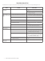
ISSUE CAUSE SOLUTION
Unit does not work aer
installation.
1. e power source is not turned ON. A. Ensure power is ON for the circuit breaker and
unit.
B. Check for an open fuse or circuit breaker in the
building’s service panel.
Light indicates power
ON but motor doesn’t
turn.
1. Plug-in connections for motor may be loose. 1. Check that the two plug-in connections for the
motor and the control are seated rmly in place.
2. Motor wiring may be damaged. 2. Change the motor. Servicing may be required.
3. e motor is not secured. 3. Tighten the motor in place.
4. Damaged blower wheel. 4. Replace the blower wheel. Servicing may be
required.
5. Blower wheel assembly may be loose. 5. Check that the blower wheel is rmly attached
to the motor sha and both spin freely.
Motor works but lights
do not turn on.
1. e light bulb is loose. 1. Tighten the light bulb.
e unit vibrates. 1. Damper in duct connector may be blocked. 1. Check that the back dra damper in the fan’s
duct connector pivots freely. Screws used to
attached the duct to the duct connector may be
preventing the damper from opening
2. Damper may be blocked or sealed shut. 2. Check that the back dra damper in the
wall or roof cap pivots freely. ese dampers
are sometimes mistakenly painted shut or
obstructed by bird and insect debris.
3. Venting duct too small or blockage in the duct
opening or ductwork.
3. Check the venting duct and the wall cap or roof
cap.
Bath fan is not venting
out properly.
1. Used the wrong size of ducting. 1. Use 6” duct work for best results.
TROUBLESHOOTING
For additional service inquiries, contact Cyclone servicing department at 1-888-293-5662 or Service@CycloneRangeHoods.com

9Bathroom Exhaust Fan Installation - English
CYCLONE HUSHTONE BATHROOM EXHAUST FAN
LIMITED WARRANTY
North America Range Hoods Inc. (hereunder called “e Company”) provides a warranty that its products are free from defects
in workmanship and materials for a period of one (1) year from the date of purchase for the following models: C50, C90, CB50, CB80
and for a period of three years for the following models: ESCB80 (H/L/S/HL/HM/SL/SM), ESCB110 (H/L/S/HL/HM/SL/SM), CBD120
(H/L/S/HL/HM/SL/SM), ESCB150(H/L/S/HL/HM/SL/SM). During that time period, e Company will, at the Company’s option,
repair or replace, without charge, any parts or complete unit found to be defective. is warranty is not transferable from the original
purchaser. e company reserves the right to use functionally equivalent reconditioned parts or products as warranty replacement or as
part of warranty service. Warranty does not cover the costs of removal, installation and/or transportation of defective products.
THE COMPANY WILL NOT BE HELD RESPONSIBLE FOR ANY CLAIMS OVER THE ORIGINAL PURCHASE PRICE
OF THE PRODUCTS NOR BE LIABLE FOR INCIDENTAL, CONSEQUENTIAL OR SPECIAL DAMAGES ARISING OUT OF OR
IN CONNECTION WITH PRODUCT USE OR PERFORMANCE.
Some provinces/states do not allow the exclusion or limitation of incidental or consequential damages, so the above limitation
or exclusion may not apply to you.
e unit removal and re-installation works are under the customer responsibility.
is warranty does not cover any costs related to the products including but not limited to:
a) Normal maintenance service required for the products; b) light bulbs, grill covers, adapters and other accessories for ducting;
c)natural wear of the nish of the products or wear caused by improper maintenance, use of corrosive and abrasive cleaning products; d)
products or parts which have been subject to freight damage, misuse, negligence, accident or any other circumstances beyond the control
of e Company. e) In addition, this warranty does not apply to the following items:
• Damage or loss sustained in natural calamity such as re, earthquake, ood, thunder, electrical storm, etc.
• Damage or loss resulting from any unreasonable use, misuse, abuse, negligence, or improper maintenance of the product.
• Damage or loss resulting from removal, improper repair, or modication of the product.
• Damage or loss resulting from sediments or foreign matter contained in a water system.
• Damage or loss resulting from improper installation or from installation of a unit in a harsh and/or hazardous environment.
• Acts of God or any circumstances beyond e Company.
e warranty will be automatically void if any of the following apply:
i. Used for cooking ventilation;
ii. Commercial use of the products or use otherwise inconsistent with its intended purpose;
iii. e function of part or the complete assembly has been modied or repaired by unauthorized person;
iv. Faulty installation or installation contrary to recommended installation instructions:
v. Ventilation system has not been vented to the outside or ventilation system stuck;
vi. e venting duct turned downward anywhere in the venting system;
vii. Wrong electrical wire connection for the fan.
To qualify for warranty service you must: (a) notify us at the address and telephone number, stated below within 2 days of the
discovery of the defect; (b) provide the model number and serial number; and (c) describe the nature of any defect in the product or part.
At the time of requesting for service, you must present evidence of your proof of purchase and proof of the original purchase date. If
we determine that the warranty exclusions listed above apply or if you fail to provide the necessary documentation to obtain service,
customer will be responsible for all shipping, travel, labor and other costs related to the service.
Warning! e Company will not be responsible for any defects caused by kitchen installation applications. is Product is not intended
for kitchen exhaust applications.
For warranty services or repair, please contact the dealer from whom you purchased the product or the address shown below.
North America Range Hoods Inc.
Canada: 1361 Huntingwood Drive, Unit 16, Scarborough, ON M1S 3J1
USA: 64 Salem Street, Medford, MA 02155
Tel: 1-888-293-5662 or (416) 293-0933 Fax (416) 293-4793
Email: Info@CycloneRangeHoods.com
Website: www.CycloneRangeHoods.com
-
 1
1
-
 2
2
-
 3
3
-
 4
4
-
 5
5
-
 6
6
-
 7
7
-
 8
8
-
 9
9


Ask a question and I''ll find the answer in the document
Finding information in a document is now easier with AI
Other documents
-
 Instant Mosaic SE110 User manual
-
Sterling SE150 Installation guide
-
 Airzone SE80SC User manual
-
Ortech ODD30-8010 User manual
-
 KAZE APPLIANCES SEP120 User manual
-
CANARMNA CEP80 Owner's manual
-
GE BFL125UQ User manual
-
Broan AERN110L Installation guide
-
Shurtape 241588 Operating instructions
-
Broan A80 User manual


