
X5 AC Drive
user's manual

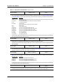
Need Help?
This manual answers most installation and startup questions
that may arise. However, if you have any problems,
please let your first call be to us.
Vacon, Inc.
Chambersburg, PA 17202
Normal business hours:
(North America)
8:00 AM to 5:00 PM, Eastern time
+1 877-Vacon06
(+1 877-822-6606)
After-hours support is also available
and Vacon, Inc. are trademarks of Vacon Plc, a member of Vacon Group.
All other product names are trademarks of their respective companies.
Copyright 2009, Vacon, Incorporated. All rights reserved.

X5 AC Drive User’s Manual X5 Parameter Summary Table
DPD00089A - iii - © 2009 Vacon Incorporated All Rights Reserved
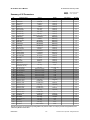
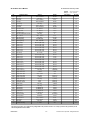
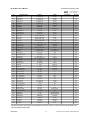
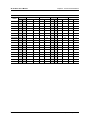
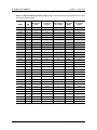
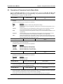
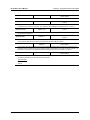
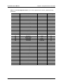
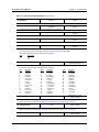
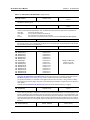
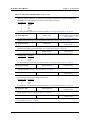
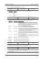
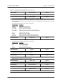
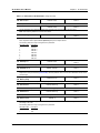
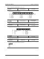
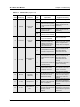
Summary of X5 Parameters
No. Parameter Name Options Default User Setting See Page
001 Model Number Model dependent Read-only 71
002 Software Rev 0.00-99.99 Read-only 71
003 Rated Current 0.0-200.0 A Read-only 71
005 Serial No. 1 0-65535 Read-only 71
006 Serial No. 2 0-65535 Read-only 71
007 USB Soft. Rev 0.00 - 99.99 Read-only 71
008 Option Installed text string Read-only 71
009 Fbus Soft. Rev 0.00 - 99.99 Read-only 71
030 Pwr Down Date dd/mm/yy Read-only 71
031 Pwr Down Time Dd/hh/mm (Dd = Tu, Th, etc.) Read-only 72
102 Output Freq 0.0-400.0 Hz Read-only 72
103 Output Voltage 0-600 V Read-only 72
104 Output Current 0.0-200.0 A Read-only 72
105 Drive Load -200.0-200.0% Read-only 72
106 Load Torque -200.0-200.0% Read-only 72
107 Drive Temp -20.0-200.0 °C Read-only 72
108 Total Run Time 0.0-6553.5 h Read-only 72
109 Power On Hours 0-65535 h Read-only 72
110 Stator Freq 0.0-400.0 Hz Read-only 72
111 DC Bus Voltage 0 - 1000 Vdc Read-only 72
115 Drive Power Out 0.0-200.0% Read-only 72
116 Out Power (kW) 0.0 - 327.67 Read-only 72
117 MWh Meter 0 - 32767 Read-only 72
118 kWh Meter 0.0 - 999.9 Read-only 72
120 Today’s Date MM/dd/YY Read-only 73
121 Today’s Time hh:mm Read-only 73
150
Show Clock Parameters
(Parameters 151-179)
text string 0 (No) 73
151 Tiime Zone Setup text string 12 (-5 East. US) 73
152 TOD Run Enable 0-23 hours, 0-59 min 12:00 73
154 TOD Run Disable 0-23 hours, 0-59 min 12:00 73
156 TOD Run En 2 0-23 hours, 0-59 min 12:00 73
158 TOD Run Dis 2 0-23 hours, 0-59 min 12:00 74
160 Weekend TOD En 0-23 hours, 0-59 min 12:00 74
162 Weekend TOD Dis 0-23 hours, 0-59 min 12:00 74
171 Reminder 1 Conf. text string 0 (disabled) 74
172 Reminder 1 Time 1-32000 hours 1 74
173 Reminder 1 ETA +/- 32000 hours Read-only 74
174 Reminder 2 Conf. text string 0 (disabled) 74
175 Reminder 2 Time 1-32000 hours 1 74
176 Reminder 2 ETA +/- 32000 hours Read-only 74
177 Reminder 3 Conf. text string 0 (disabled) 75
178 Reminder 3 Time 1-32000 hours 1 75
179 Reminder 3 ETA +/- 32000 hours Read-only 75
201 Input Mode text string Local Only 75
202 Rev Enable text string Forward 75
203 Stop Key Remote text string Coast 76
204 Ref Select text string Vin1 76
205 Vin1 Config text string 0-10V 77
206 Vin1 Offset 0.0% to 100.0% 0.00% 77
= cannot change in Run
Bold type = Level 1 parameter
Note that all parameters can be addressed by adding 40000 to the parameter number. For example, parameter 201 (Input Mode) can be
addressed by Modbus address 40201.

X5 AC Drive User’s Manual X5 Parameter Summary Table
DPD00089A - iv - © 2009 Vacon Incorporated All Rights Reserved
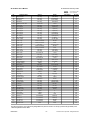
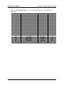
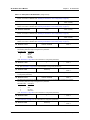
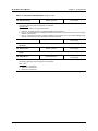
207 Vin1 Span 10.0% to 200.0% 100.00% 77
208 Cin Config text string 0-20mA 50 77
209 Cin Offset 0.0% to 100.0% 0.0% 77
210 Cin Span 10.0% to 200.0% 100.0% 78
211 Vin2 Config text string 0-10V 78
212 Vin2 Offset 0.0% to 100.0 % 0.00% 78
213 Vin2 Span 10.0% to 200.0% 100.00% 78
214 Vin1 Filter Time 0 to 1000 ms 20 ms 78
215 Cin Filter Time 0 to 1000 ms 20 ms 78
216 Vin2 Filter Time 0 to 1000 ms 20 ms 78
217 Trim Ref Enable (Set k-Factor) text string 0 78
218 Trim % Factor -100.0 - 100.0% 0.0% 79
222 Ref Loss Config text string No Fault 79
301 Min Frequency 0.0 - Max Freq. 0.0 Hz 79
302 Max Frequency 20.0 - 400.0 Hz 60.0 Hz 79
303 Preset Freq 1 Min Freq-Max Freq 5.0 Hz 79
304 Preset Freq 2 Min Freq-Max Freq 10.0 Hz 79
305 Preset Freq 3 Min Freq-Max Freq 20.0 Hz 79
306 Preset Freq 4 Min Freq-Max Freq 30.0 Hz 79
307 Preset Freq 5 Min Freq-Max Freq 40.0 Hz 79
308 Preset Freq 6 Min Freq-Max Freq 50.0 Hz 79
309 Cut-off Freq 0.0 - 5.0 Hz 0.0 Hz 79
310 Preset Freq 7 Min Freq-Max Freq 60.0 Hz 79
311 Preset Freq 8 Min Freq-Max Freq 0.0 Hz 79
312 Preset Freq 9 Min Freq-Max Freq 2.5 Hz 79
313 Preset Freq 10 Min Freq-Max Freq 7.5 Hz 79
314 Preset Freq 11 Min Freq-Max Freq 15.0 Hz 79
315 Preset Freq 12 Min Freq-Max Freq 25.0 Hz 79
316 Preset Freq 13 Min Freq-Max Freq 35.0 Hz 79
317 Preset Freq 14 Min Freq-Max Freq 45.0 Hz 79
318 Preset Freq 15 Min Freq-Max Freq 55.0 Hz 79
380 Keeper Input Cfg text string 4 (disabled) 79
381 Keeper Max Scale 0-32000 1000 80
382 Keeper Save Time 00:00 - 23:59 0:00 80
384 Keeper Save Rate text string 0 (24 hour) 80
385 Keeper Input Value 0-32000 Read-only 80
386 Keeper Time Rate text string 1 (minute) 80
387 Keeper Rec. Num 0-255 Read-only 80
388 Active Kpr. Record 0-255 Read-only 80
389 Keeper Units text string 1 (GPM) 81
401 Ramp Select text string ART-DI 81
402 Accel Time 1 0.1-3200.0 sec 5.0 sec 81
403 Decel Time 1 0.1-3200.0 sec 5.0 sec 81
404 Accel Time 2 0.1-3200.0 sec 3.0 sec 82
405 Decel Time 2 0.1-3200.0 sec 3.0 sec 82
406 DC Inject Config text string DC at Stop 82
407 DC Inject Time 0.0-5.0 sec 0.2 sec 82
408 DC Inject Level 0.0% to 100.0% 50.0% 82
409 DC Inj Freq 0.0 to 20.0 Hz 0.0 Hz 82
410 DB Config text string Internal 83
414 S Ramp Rounding 1 - 100% 25% 83
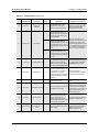
No. Parameter Name Options Default User Setting See Page
= cannot change in Run
Bold type = Level 1 parameter
Note that all parameters can be addressed by adding 40000 to the parameter number. For example, parameter 201 (Input Mode) can be
addressed by Modbus address 40201.

X5 AC Drive User’s Manual X5 Parameter Summary Table
DPD00089A - v - © 2009 Vacon Incorporated All Rights Reserved
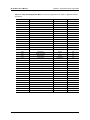
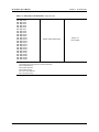
415 Accel Time 3 0.1-3200.0 sec 10.0 sec 83
416 Decel Time 3 0.1-3200.0 sec 10.0 sec 83
417 Accel Time 4 0.1-3200.0 sec 15.0 sec 84
418 Decel Time 4 0.1-3200.0 sec 15.0 sec 84
490 App Macro text string Factory 84
491 Seq Appl text string Disabled 84
492 SIO Visible text string No 84
501 V/Hz Select text string Linear Fixed 85
502 Voltage Boost 0.0-50% 1.0% 85
503 V/Hz Knee Freq 25.0-400.0 Hz 60.0 Hz 85
504 Skip Freq Band 0.2-20.0 Hz 0.2 Hz 86
505 Skip Freq 1 Min Freq-Max Freq 0.0 Hz 86
506 Skip Freq 2 Min Freq-Max Freq 0.0 Hz 86
507 Skip Freq 3 Min Freq-Max Freq 0.0 Hz 86
508 Skip Freq 4 Min Freq-Max Freq 0.0 Hz 86
509 Rated Mtr Volt 100V-690V Model dependent 86
510 Rated Mtr FLA 50% - 200% of ND Rating ND Rating 86
511 Rated Mtr RPM 0-24000 rpm 1750 rpm 86
512 Midpoint Freq 0.0 Hz-V/Hz Knee Freq 60.0 Hz 86
513 Midpoint Volt 0.0-100.0% 100.0% 86
514 Motor RS 0.0-655.35 Ohms Model dependent 86
515 Power Factor 0.50-1.00 0.80 86
516 Slip Comp Enable text string No 87
517 Single Phase text string No 87
519 Find Mtr Data Not active / Motor RS Not active 87
520 Filter FStator 1 - 100 ms 8 ms 87
521 Start Field En text string No 87
522 Filter Time Slip 10 - 1000 ms 100 ms 88
523 Id Percent 0 - 200% Read-only 88
524 Iq Percent 0 - 200% Read-only 88
525 Power Fail Config text string CTS No Msg 88
526 UV Ride-Thru En text string w/ LVT 88
600 Current Lim Sel text string 0 89
601 Cur Lim Mtr Fwd 5%-150% 120% 89
602 Cur Lim Mtr Rev 5%-150% 120% 89
603 Cur Lim Reg Fwd 5%-150% 80% 89
604 Cur Lim Reg Rev 5%-150% 80% 89
605 Cur Lim Freq 0.0 - 400.0 Hz 3.0 Hz 89
606 Ramp Time CL 0.1-3200.0 sec 1.0 sec 89
607 Cur Limit Minimum 0 - 50% 10% 89
608 Restart Number text string 0 90
609 Restart Delay 0-60 sec 60 sec 90
610 Timed OL Select text string 0 (Std Ind 60s) 90
613 Max Regen Ramp 100 - 1000% 300% 91
614 Stability Gain 0 - 10 Model Dependent 91
615 Stability Rate 0 - 1000 Model Dependent 91
700 Vmet Config text string Freq Out 91
701 Vmet Span 0.0-200.0% 100.0% 91
702 Imet Config text string Drive Load 92
703 Imet Span 0.0-200.0% 100.0% 92
704 Imet Offset 0.0-90.0-% 0.0% 92
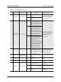
No. Parameter Name Options Default User Setting See Page
= cannot change in Run
Bold type =Level 1 parameter
Note that all parameters can be addressed by adding 40000 to the parameter number. For example, parameter 201 (Input Mode) can be
addressed by Modbus address 40201.

X5 AC Drive User’s Manual X5 Parameter Summary Table
DPD00089A - vi - © 2009 Vacon Incorporated All Rights Reserved
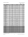
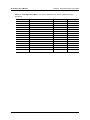
705 Relay 1 Select text string 1 (Drv Fault) 93
706 Relay 2 Select text string 2 (Drive Run) 93
707 DO1 Select text string 0 (Drv Ready) 93
708 DO2 Select text string 6 (At Speed) 93
719 Digital Input Filter Time 1-1000 msec 5 msec 94
720 Active Logic text string 1 (Active High) 94
721 DI1 Configure text string 0 (Preset 1) 95
722 DI2 Configure text string 1 (Preset 2) 95
723 DI3 Configure text string 2 (Preset 3) 95
724 DI4 Configure text string 6 (Alt Ramp) 95
725 DI5 Configure text string 7 (Fault Reset) 95
726 MOL Polarity text string 1 (NO Operate) 96
727 MOL Configure text string 21 (MOL) 95
740 Thres 1 Select text string 9 (Load High) 96
741 Thres 1 High -300.00 to 300.00% 100.00% 96
742 Thres 1 Low -300.00 to 300.00% 0.00% 96
743 Thres 2 Select text string 15 (Current High) 97
744 Thres 2 High -300.00 to 300.00% 100.00% 97
745 Thres 2 Low -300.00 to 300.00% 0.00% 97
746 Timer 1 Type text string 0 (On Delay) 97
747 Timer 1 Signal text string 1 (Drv Fault) 97
748 Timer 1 Time 0.0 - 320.0 sec 1.0 sec 97
749 Timer 2 Type text string 0 (On Delay) 97
750 Timer 2 Signal text string 1 (Drv Fault) 98
751 Timer 2 Time 0.0 - 320.0 sec 1.0 sec 98
794 Drive Name text string serial number 98
799 Config USB Mode text string 0 (Disabled) 98
801 Program Number 0-9999 0 99
802 Start Options text string 0 (LS Lockout) 99
803 PWM Frequency 0.6-16.0 kHz 3.0 kHz 100
804 Display Mode text string 0 = Std Disply 100
805 Display Units alphanumeric 0 (blank) 100
809 Display Scale 1-65535 18000 100
810 Language text string 0 (English) 100
811 Access Code 0-9999 0 101
812 Freq Ref Output text string 0 (6FS) 101
813 Speed Ratio 0.0-200.0% 100.0% 101
814 Display Status text string 0 (Drive load) 101
816 Fly Catch Mode text string 0 (Sweep FWD) 101
819 Flt Text #1 text string User Flt 1 101
825 Flt Text #2 text string User Flt 2 102
850 PID Configure text string 0 (No PID) 102
851 PID FBk Config text string 0 (Vin1) 102
852 PID Prop Gain 0-2000 0 102
853 PID Int Gain 0-10000 0 102
854 PID Feed Gain 0-2000 1000 102
855 PID Error 1 0.00-100.00% Read-only 102
856 PID Error 2 0.00-100.00% Read-only 102
857 PID High Corr 0.00-100.00% 100.00% 103
858 PID Low Corr 0.00-100.00% 0.00% 103
859 PID Deriv Gain 0-200 0.00% 103
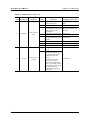
No. Parameter Name Options Default User Setting See Page
= cannot change in Run
Bold type = Level 1 parameter
Note that all parameters can be addressed by adding 40000 to the parameter number. For example, parameter 201 (Input Mode) can be
addressed by Modbus address 40201.

X5 AC Drive User’s Manual X5 Parameter Summary Table
DPD00089A - vii - © 2009 Vacon Incorporated All Rights Reserved
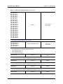
860 PID Sleep Cfg text string 0 (disabled) 103
861 PID Sleep Lvl 0.00-100.00% 0.00% 103
862 PID Wake-up Lvl 0.00-100.00% 100.00% 103
863 Sleep Delay Time 0.0-300.0 sec 0.0 sec 103
864 Wake-up Delay 0.0-300.0 sec 0.0 sec 103
865 PID Feedback 0.00-100.00% Read-only 103
866 PID Reference 0.00-100.00% Read-only 103
867 PID User Units text string 0 (No) 103
880 FBus Read 1 0-65535 103 104
881 FBus Read 2 0-65535 104 104
882 FBus Read 3 0-65535 105 104
883 FBus Read 4 0-65535 107 104
884 FBus Read 5 0-65535 909 104
890 FBus Write 1 0-65535 907 104
891 FBus Write 2 0-65535 402 104
892 FBus Write 3 0-65535 403 104
893 FBus Write 4 0-65535 920 104
894 FBus Write 5 0-65535 921 104
900 SIO Protocol text string 0 (RTU N81) 104
901 SIO Baud Rate text string 2 (9600) 104
902 Comm Drop # 1-247 1 104
903 SIO Timer 0.0-60.0 sec 1.0 sec 104
904 SIO Cntl Word Bit 0-15 0x0000 105
905 Ext Ref Freq1 Min-Max Freq 0.0 Hz 105
906 Ext Ref Freq2 Min-Max Freq 0.0 Hz 105
907 Cntl Word 2 Bit 0-15 0x0000 105
908 Status Word Bit 0-15 Read-only 105
909 DI Status Bit 0-14 Read-only 106
910 Vin1 Status 0.00-100.00% Read-only 106
911 Cin Status 0.00-100.00% Read-only 106
912 Vin2 Status 0.00-100.00% Read-only 106
913 Output Status Bit 0-5 Read-only 106
914 Vmet Status 0.00-100.00% Read-only 106
915 Imet Status 0.00-100.00% Read-only 106
916 Infrared Baud text string 2 (9600) 106
917 FBus Port Config text string 1 (485 w/ctl) 107
920 SIO Vmet Level 0.00-100.00% 100.00% 107
921 SIO Imet Level 0.00-100.00% 100.00% 107
926 Status Word 2 Bit 0-2 Read-only 107
930 Seq Cntl 1 Bit 0-15 (hex control) 0x0000 108
931 Seq Cntl 2 Bit 0-15 (hex control) 0x0000 108
932 Seq Cntl 3 Bit 0-15 (hex control) 0x0000 108
933 Seq Cntl 4 Bit 0-15 (hex control) 0x0000 108
934 Seq Cntl 5 Bit 0-15 (hex control) 0x0000 108
935 Seq Cntl 6 Bit 0-15 (hex control) 0x0000 108
936 Seq Cntl 7 Bit 0-15 (hex control) 0x0000 108
937 Seq Cntl 8 Bit 0-15 (hex control) 0x0000 108
938 Seq Cntl 9 Bit 0-15 (hex control) 0x0000 108
939 Seq Cntl 10 Bit 0-15 (hex control) 0x0000 108
940 Seq Cntl 11 Bit 0-15 (hex control) 0x0000 108
941 Seq Cntl 12 Bit 0-15 (hex control) 0x0000 108
942 Seq Cntl 13 Bit 0-15 (hex control) 0x0000 108
No. Parameter Name Options Default User Setting See Page
= cannot change in Run
Bold type = Level 1 parameter
Note that all parameters can be addressed by adding 40000 to the parameter number. For example, parameter 201 (Input Mode) can be
addressed by Modbus address 40201.

X5 AC Drive User’s Manual X5 Parameter Summary Table
DPD00089A - viii - © 2009 Vacon Incorporated All Rights Reserved
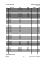
943 Seq Cntl 14 Bit 0-15 (hex control) 0x0000 108
944 Seq Cntl 15 Bit 0-15 (hex control) 0x0000 108
945 Seq Cntl 16 Bit 0-15 (hex control) 0x0000 108
946 Seq Cntl 17 Bit 0-15 (hex control) 0x0000 108
947 Seq Cntl 18 Bit 0-15 (hex control) 0x0000 108
948 Seq Cntl 19 Bit 0-15 (hex control) 0x0000 108
949 Seq Cntl 20 Bit 0-15 (hex control) 0x0000 108
950 Seq Cntl 21 Bit 0-15 (hex control) 0x0000 108
951 Seq Cntl 22 Bit 0-15 (hex control) 0x0000 108
952 Seq Cntl 23 Bit 0-15 (hex control) 0x0000 108
953 Seq Cntl 24 Bit 0-15 (hex control) 0x0000 108
954 Seq Cntl 25 Bit 0-15 (hex control) 0x0000 108
955 Seq Count 1 0-65535 0 109
956 Seq Count 2 0-65535 0 109
957 Seq Count 3 0-65535 0 109
958 Seq Count 4 0-65535 0 109
959 Seq Count 5 0-65535 0 109
960 Seq Count 6 0-65535 0 109
961 Seq Count 7 0-65535 0 109
962 Seq Count 8 0-65535 0 109
963 Seq Count 9 0-65535 0 109
964 Seq Count 10 0-65535 0 109
965 Seq Count 11 0-65535 0 109
966 Seq Count 12 0-65535 0 109
967 Seq Count 13 0-65535 0 109
968 Seq Count 14 0-65535 0 109
969 Seq Count 15 0-65535 0 109
970 Seq Count 16 0-65535 0 109
971 Seq Count 17 0-65535 0 109
972 Seq Count 18 0-65535 0 109
973 Seq Count 19 0-65535 0 109
974 Seq Count 20 0-65535 0 109
975 Seq Count 21 0-65535 0 109
976 Seq Count 22 0-65535 0 109
977 Seq Count 23 0-65535 0 109
978 Seq Count 24 0-65535 0 109
979 Seq Count 25 0-65535 0 109
980 Seq Decision 1 Bit 0-15 0x0000 109
981 Seq Decision 2 Bit 0-15 0x0000 109
982 Seq Decision 3 Bit 0-15 0x0000 109
983 Seq Decision 4 Bit 0-15 0x0000 109
984 Seq Decision 5 Bit 0-15 0x0000 109
1500 Last Fault All fault options Read-only 109
1527 9th Fault All fault options Read-only 109
1554 8th Fault All fault options Read-only 109
1581 7th Fault All fault options Read-only 109
1608 6th Fault All fault options Read-only 110
1635 5th Fault All fault options Read-only 110
1662 4th Fault All fault options Read-only 110
1689 3rd Fault All fault options Read-only 110
1716 2nd Fault All fault options Read-only 110
1743 1st Fault All fault options Read-only 110
No. Parameter Name Options Default User Setting See Page
= cannot change in Run
Bold type = Level 1 parameter
Note that all parameters can be addressed by adding 40000 to the parameter number. For example, parameter 201 (Input Mode) can be
addressed by Modbus address 40201.

X5 AC Drive User’s Manual Table of Contents
DPD00089A - ix - © 2009 Vacon Incorporated All Rights Reserved
CONTENTS
Summary of X5 Parameters . . . . . . . . . . . . . . . . . . . . . . . . . . . . . . . . . . . . . . . . . . . . . . . . . . . iii
Chapter 1: Introduction . . . . . . . . . . . . . . . . . . . . . . . . . . . . . . . . . . . . . . . . . . . . . . . . . . . . . 12
1.1 Product Overview . . . . . . . . . . . . . . . . . . . . . . . . . . . . . . . . . . . . . . . . . . . . . . . . . . . 12
1.2 Overview of This Manual . . . . . . . . . . . . . . . . . . . . . . . . . . . . . . . . . . . . . . . . . . . . . 12
1.3 User’s Manual Publication History. . . . . . . . . . . . . . . . . . . . . . . . . . . . . . . . . . . . . . 13
Chapter 2: Technical Characteristics . . . . . . . . . . . . . . . . . . . . . . . . . . . . . . . . . . . . . . . . . . 14
2.1 Interpreting Model Numbers . . . . . . . . . . . . . . . . . . . . . . . . . . . . . . . . . . . . . . . . . . 14
2.2 Power and Current Ratings . . . . . . . . . . . . . . . . . . . . . . . . . . . . . . . . . . . . . . . . . . . . 16
2.3 Environmental Specifications . . . . . . . . . . . . . . . . . . . . . . . . . . . . . . . . . . . . . . . . . . 18
2.4 Electrical Specifications . . . . . . . . . . . . . . . . . . . . . . . . . . . . . . . . . . . . . . . . . . . . . . 18
2.5 Control Features Specifications . . . . . . . . . . . . . . . . . . . . . . . . . . . . . . . . . . . . . . . . 19
2.6 Dimensions and Weights . . . . . . . . . . . . . . . . . . . . . . . . . . . . . . . . . . . . . . . . . . . . . 20
Chapter 3: Receiving and Installation. . . . . . . . . . . . . . . . . . . . . . . . . . . . . . . . . . . . . . . . . . 24
3.1 Preliminary Inspection . . . . . . . . . . . . . . . . . . . . . . . . . . . . . . . . . . . . . . . . . . . . . . . 24
3.2 Installation Precautions. . . . . . . . . . . . . . . . . . . . . . . . . . . . . . . . . . . . . . . . . . . . . . . 24
3.3 Dissipation Requirements . . . . . . . . . . . . . . . . . . . . . . . . . . . . . . . . . . . . . . . . . . . . . 25
3.4 Cover Assembly and Torque Specifications. . . . . . . . . . . . . . . . . . . . . . . . . . . . . . . 26
3.5 Serial Number Label. . . . . . . . . . . . . . . . . . . . . . . . . . . . . . . . . . . . . . . . . . . . . . . . . 27
3.6 Conduit Usage. . . . . . . . . . . . . . . . . . . . . . . . . . . . . . . . . . . . . . . . . . . . . . . . . . . . . . 27
3.7 Condensation . . . . . . . . . . . . . . . . . . . . . . . . . . . . . . . . . . . . . . . . . . . . . . . . . . . . . . 27
Chapter 4: Connections . . . . . . . . . . . . . . . . . . . . . . . . . . . . . . . . . . . . . . . . . . . . . . . . . . . . . 28
4.1 Introduction . . . . . . . . . . . . . . . . . . . . . . . . . . . . . . . . . . . . . . . . . . . . . . . . . . . . . . . 29
4.2 General Wiring Information . . . . . . . . . . . . . . . . . . . . . . . . . . . . . . . . . . . . . . . . . . 29
4.2.1 Wiring Practices . . . . . . . . . . . . . . . . . . . . . . . . . . . . . . . . . . . . . . . . . . . 29
4.2.2 Considerations for Power Wiring. . . . . . . . . . . . . . . . . . . . . . . . . . . . . . . 29
4.2.3 Considerations for Control Wiring . . . . . . . . . . . . . . . . . . . . . . . . . . . . . 30
4.3 Input Line Requirements . . . . . . . . . . . . . . . . . . . . . . . . . . . . . . . . . . . . . . . . . . . . . 31
4.3.1 Line Voltage . . . . . . . . . . . . . . . . . . . . . . . . . . . . . . . . . . . . . . . . . . . . . . 31
4.3.2 Line Capacity . . . . . . . . . . . . . . . . . . . . . . . . . . . . . . . . . . . . . . . . . . . . . 31
4.3.3 Phase Imbalance . . . . . . . . . . . . . . . . . . . . . . . . . . . . . . . . . . . . . . . . . . . 31
4.3.4 Single-phase Operation . . . . . . . . . . . . . . . . . . . . . . . . . . . . . . . . . . . . . . 32
4.3.5 Ground Fault Circuit Interrupters (GFCI) . . . . . . . . . . . . . . . . . . . . . . . . 32
4.3.6 Motor Lead Length . . . . . . . . . . . . . . . . . . . . . . . . . . . . . . . . . . . . . . . . . 32
4.3.7 Using Output Contactors . . . . . . . . . . . . . . . . . . . . . . . . . . . . . . . . . . . . . 32
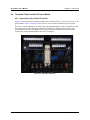
4.4 Terminals Found on the X5 Power Board . . . . . . . . . . . . . . . . . . . . . . . . . . . . . . . . 33
4.4.1 Description of the Terminals . . . . . . . . . . . . . . . . . . . . . . . . . . . . . . . . . . 33
4.4.2 Typical Power Connections . . . . . . . . . . . . . . . . . . . . . . . . . . . . . . . . . . 34
4.5 Dynamic Braking . . . . . . . . . . . . . . . . . . . . . . . . . . . . . . . . . . . . . . . . . . . . . . . . . . . 36

X5 AC Drive User’s Manual Table of Contents
DPD00089A - x - © 2009 Vacon Incorporated All Rights Reserved
4.6 Terminals Found on the X5 Control Board . . . . . . . . . . . . . . . . . . . . . . . . . . . . . . . 38
4.6.1 Description of the Control Terminals . . . . . . . . . . . . . . . . . . . . . . . . . . . 38
4.6.2 Typical Connection Diagrams for Digital Inputs . . . . . . . . . . . . . . . . . . 41
4.6.3 Typical Connection Diagrams for Analog Inputs . . . . . . . . . . . . . . . . . . 42
4.6.4 Typical Connection Diagrams for Analog Outputs . . . . . . . . . . . . . . . . 42
4.6.5 Modbus Connection Diagram . . . . . . . . . . . . . . . . . . . . . . . . . . . . . . . . . 43
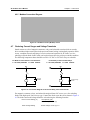
4.7 Reducing Current Surges and Voltage Transients . . . . . . . . . . . . . . . . . . . . . . . . . . 43
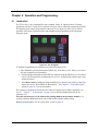
Chapter 5: Operation and Programming . . . . . . . . . . . . . . . . . . . . . . . . . . . . . . . . . . . . . . 44
5.1 Introduction . . . . . . . . . . . . . . . . . . . . . . . . . . . . . . . . . . . . . . . . . . . . . . . . . . . . . . . 44
5.2 Keypad Operation . . . . . . . . . . . . . . . . . . . . . . . . . . . . . . . . . . . . . . . . . . . . . . . . . . 45
5.3 LCD Displays . . . . . . . . . . . . . . . . . . . . . . . . . . . . . . . . . . . . . . . . . . . . . . . . . . . . . 47
5.3.1 Control . . . . . . . . . . . . . . . . . . . . . . . . . . . . . . . . . . . . . . . . . . . . . . . . . . 47
5.3.2 X5 Keypad Status and Warning Messages . . . . . . . . . . . . . . . . . . . . . . . 47
5.3.3 Rights . . . . . . . . . . . . . . . . . . . . . . . . . . . . . . . . . . . . . . . . . . . . . . . . . . . 49
5.3.4 Other Data . . . . . . . . . . . . . . . . . . . . . . . . . . . . . . . . . . . . . . . . . . . . . . . . 49
5.4 Keypad Display Window . . . . . . . . . . . . . . . . . . . . . . . . . . . . . . . . . . . . . . . . . . . . . 49
5.5 Programming . . . . . . . . . . . . . . . . . . . . . . . . . . . . . . . . . . . . . . . . . . . . . . . . . . . . . . 50
5.5.1 Accessing Parameters . . . . . . . . . . . . . . . . . . . . . . . . . . . . . . . . . . . . . . . 50
5.5.2 Changing the Display Scroll Rate . . . . . . . . . . . . . . . . . . . . . . . . . . . . . . 50
5.5.3 Programming Procedure . . . . . . . . . . . . . . . . . . . . . . . . . . . . . . . . . . . . . 50
5.5.4 Restoring Factory Settings . . . . . . . . . . . . . . . . . . . . . . . . . . . . . . . . . . . 51
5.5.5 Viewing Parameters That Have Changed . . . . . . . . . . . . . . . . . . . . . . . . 51
5.5.6 Using Macro Mode . . . . . . . . . . . . . . . . . . . . . . . . . . . . . . . . . . . . . . . . . 51
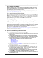
5.6 Measuring Stator Resistance (RS Measurement) . . . . . . . . . . . . . . . . . . . . . . . . . . 51
5.6.1 Activating Automatic RS Measurement via Keypad . . . . . . . . . . . . . . . 51
5.6.2 Activating Automatic RS Measurement via Serial Link (Modbus) . . . . 52
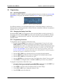
5.7 Storing Data and Reflashing Using a Flash Memory Device . . . . . . . . . . . . . . . . . 52
5.7.1 Storing Drive Parameters . . . . . . . . . . . . . . . . . . . . . . . . . . . . . . . . . . . . 52
5.7.2 Recalling Drive Parameters . . . . . . . . . . . . . . . . . . . . . . . . . . . . . . . . . . . 53
5.7.3 Storing Keeper Files . . . . . . . . . . . . . . . . . . . . . . . . . . . . . . . . . . . . . . . . 53
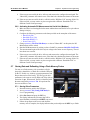
5.7.4 Reflashing the X5 Using the USB Port and a Flash Memory Device . . 53
5.8 Using the Keeper Data Log . . . . . . . . . . . . . . . . . . . . . . . . . . . . . . . . . . . . . . . . . . . 55
5.8.1 Keeper Parameters . . . . . . . . . . . . . . . . . . . . . . . . . . . . . . . . . . . . . . . . . 55
5.8.2 Setting up the Keeper Function . . . . . . . . . . . . . . . . . . . . . . . . . . . . . . . . 56
5.9 Using the X5 Real-Time Clock and Other Special Features . . . . . . . . . . . . . . . . . . 57
5.9.1 Enabling the X5 Based on Time of Day (TOD) . . . . . . . . . . . . . . . . . . . 57
5.9.2 Reminders . . . . . . . . . . . . . . . . . . . . . . . . . . . . . . . . . . . . . . . . . . . . . . . . 58
5.9.3 Timers . . . . . . . . . . . . . . . . . . . . . . . . . . . . . . . . . . . . . . . . . . . . . . . . . . . 58
5.9.4 Thresholds . . . . . . . . . . . . . . . . . . . . . . . . . . . . . . . . . . . . . . . . . . . . . . . . 58
Chapter 6: Using Macro Mode and Getting a Quick Start . . . . . . . . . . . . . . . . . . . . . . . . 60
6.1 Entering Macro Mode . . . . . . . . . . . . . . . . . . . . . . . . . . . . . . . . . . . . . . . . . . . . . . . 60
6.2 Description of Parameters Used in Macro Mode . . . . . . . . . . . . . . . . . . . . . . . . . . . 61
6.3 Macro Mode Applications and Included Parameters . . . . . . . . . . . . . . . . . . . . . . . . 63
6.4 Getting a Quick Start . . . . . . . . . . . . . . . . . . . . . . . . . . . . . . . . . . . . . . . . . . . . . . . . 69

X5 AC Drive User’s Manual Table of Contents
DPD00089A - xi - © 2009 Vacon Incorporated All Rights Reserved
Chapter 7: X5 Parameters . . . . . . . . . . . . . . . . . . . . . . . . . . . . . . . . . . . . . . . . . . . . . . . . . . . 70
7.1 Introduction . . . . . . . . . . . . . . . . . . . . . . . . . . . . . . . . . . . . . . . . . . . . . . . . . . . . . . . 70
7.2 Level 1 Parameters . . . . . . . . . . . . . . . . . . . . . . . . . . . . . . . . . . . . . . . . . . . . . . . . . . 70
7.3 Description of Parameters . . . . . . . . . . . . . . . . . . . . . . . . . . . . . . . . . . . . . . . . . . . . 71
7.4 Using the X5 Program Sequencer . . . . . . . . . . . . . . . . . . . . . . . . . . . . . . . . . . . . . 110
7.4.1 Enabling the X5 Program Sequencer . . . . . . . . . . . . . . . . . . . . . . . . . . 110
7.4.2 Controlling the X5 Program Sequencer . . . . . . . . . . . . . . . . . . . . . . . . 111
7.4.3 Sequencer State Configuration Overview . . . . . . . . . . . . . . . . . . . . . . . 113
7.4.4 Advancement on Drive State Conditions . . . . . . . . . . . . . . . . . . . . . . . 118
7.4.5 Sequencer Decision Configuration . . . . . . . . . . . . . . . . . . . . . . . . . . . . 119
7.4.6 Sequencer Status Indicators . . . . . . . . . . . . . . . . . . . . . . . . . . . . . . . . . 120
7.4.7 Sample Sequencer Program . . . . . . . . . . . . . . . . . . . . . . . . . . . . . . . . . 121
Blank Worksheet to Remove and Copy. . . . . . . . . . . . . . . . . . . . . . . . . 123
Chapter 8: Troubleshooting and Fault Codes . . . . . . . . . . . . . . . . . . . . . . . . . . . . . . . . . . 125
Chapter 9: X5 Options . . . . . . . . . . . . . . . . . . . . . . . . . . . . . . . . . . . . . . . . . . . . . . . . . . . . . 131
Appendix A: Parameter 201 Options . . . . . . . . . . . . . . . . . . . . . . . . . . . . . . . . . . . . . . . . . 132
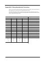
Appendix B: Binary-Hexadecimal Conversion . . . . . . . . . . . . . . . . . . . . . . . . . . . . . . . . . 133
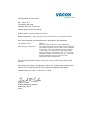
EU Declaration of Conformity . . . . . . . . . . . . . . . . . . . . . . . . . . . . . . . . . . . . . . . . . . . . . . . 135

DPD00089A - 12 - © 2009 Vacon Incorporated All Rights Reserved
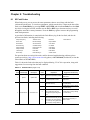
Chapter 1: Introduction
1.1 Product Overview
The X5 AC drive provides an economical, powerful solution for a large array of industrial
applications. It features remote communications capability (using Ethernet, Devicenet, Modbus
®
and
Modbus
®
TCP/IP protocols), a keypad for easy configuration, and standard NEMA 4X / IP66 and
NEMA 12 / IP55 enclosures that eliminate the need for mounting in a separate enclosure. A USB
interface allows you to copy parameters from drive to drive, and to download data logs. Like the X4
AC drive, it provides a robust, compact solution for industrial applications, but with more capability.
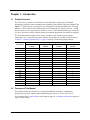
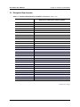
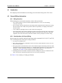
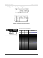
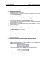
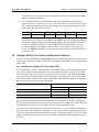
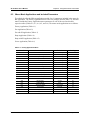
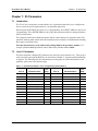
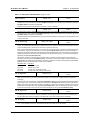
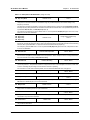
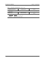
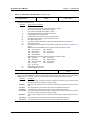
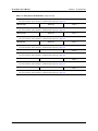
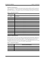
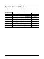
The X5 product family includes a wide variety of models to suit almost any input voltage
requirement. An ‘x’ in the following table indicates what models are currently available. Refer to
“Chapter 2: Technical Characteristics” on page 14 for help in interpreting model numbers.
1.2 Overview of This Manual
This manual contains specifications, receiving and installation instructions, configuration,
description of operation, options, and troubleshooting procedures for X5 AC drive devices.
For experienced users, a Quick-Start section begins on page 69. A summary of parameters begins on
page iii of this manual.
Horsepower
Input Voltage
115 Vac
1 Phase
230 Vac
3 Phase
460 Vac
3 Phase
575 Vac
3 Phase
1xxx x
2xxx
3xxx
5xxx
7.5 x x x
10 x x x
15 x x x
20 x x x
25 x x x
30 x x x
40 x x
50 x x
60 x x
75 x x
100 x x
125 x x
150 x x
200 x x

X5 AC Drive User’s Manual Chapter 1: Introduction
DPD00089A - 13 - © 2009 Vacon Incorporated All Rights Reserved
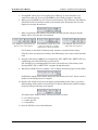
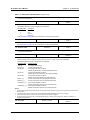
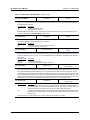
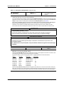
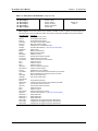
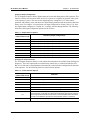
1.3 User’s Manual Publication History
Date Form Number Nature of Change
July 2007 1434 First release
April 2008 1434A
Added information regarding new models, new parameters,
and model options.
Made corrections throughout manual.
Added Appendix for Parameter 201.
June 2008 1434B
Corrected Figure 7-3 in Sequencer section.
Updated Vacon corporate information.
October 2008 DPD00089
Changed installation diagrams to reflect changes in product;
changed photographs of product; added information to Chapter 2
on current surges and voltage transients; added parameters 614-
15, 719, and changed ranges for parameters 862-864. Made
changes to Sect. 7.4.3, Sequencer State Configuration Overview.
April 2009 DPD00089A Revised EU Declaration of Conformity

DPD00089A - 14 - © 2009 Vacon Incorporated All Rights Reserved
Chapter 2: Technical Characteristics
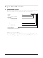
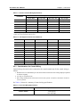
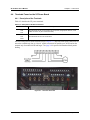
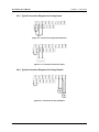
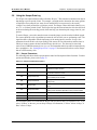
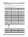
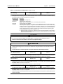
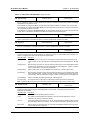
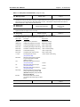
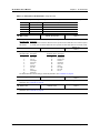
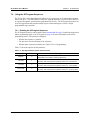
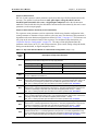
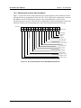
2.1 Interpreting Model Numbers
The model number of the X5 AC drive appears on the shipping carton label and on the technical data
label on the model. The information provided by the model number is shown below:
X5 C 2 0030 C 09
X5 Series
Torque:
C = Constant - Normal duty
Input Voltage:
2 = 230 Vac, Three-phase
4 = 460 Vac, Three-phase
5 = 575 Vac, Three-phase
Horsepower:
Examples: 0030 = 3 HP; 0300 = 30 HP
Enclosure:
C = NEMA 4X / IP66
D = NEMA 12 / IP55
Optional configuration
(see following section for more information)
X5 Models without option card capability
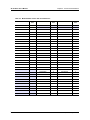
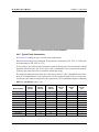
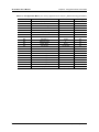
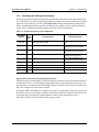
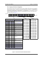
Smaller horsepower models (30 HP or less) of X5 drives with optional configuration -09 have the
same electrical capabilities as the other X5 models, but do not support option cards. These smaller-
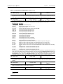
frame models are offered in smaller enclosures (frame size 0, 1, and 2). Table 2-1 shows the model
and size relationships of all the X5 drives.

X5 AC Drive User’s Manual Chapter 2: Technical Characteristics
DPD00089A - 15 - © 2009 Vacon Incorporated All Rights Reserved
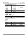
Table 2-1: Model Number / Frame Size Cross-Reference
Part #
Frame
Size
Part #
Frame
Size
Part #
Frame
Size
X5C1S010C 1
X5C1S010C09 0
X5C20010C 1 X5C40010C 1 X5C50010C 1
X5C20010C09 0 X5C40010C09 0 X5C50010C09 1A
X5C20020C 1 X5C40020C 1 X5C50020C 1
X5C20020C09 0 X5C40020C09 0 X5C50020C09 1A
X5C20030C 1 X5C40030C 1 X5C50030C 1
X5C20030C09 0 X5C40030C09 0 X5C50030C09 1A
X5C20050C 1 X5C40050C 1 X5C50050C 1
X5C20050C09 1A X5C40050C09 1A X5C50050C09 1A
X5C20075C 1 X5C40075C 1 X5C50075C 1
X5C20075C09 1A X5C40075C09 1A X5C50075C09 1A
X5C20100C 2 X5C40100C 1 X5C50100C 1
X5C20100C09 2A X5C40100C09 1A X5C50100C09 1A
X5C20150C 2 X5C40150C 2 X5C50150C 2
X5C20150C09 2A X5C40150C09 2A X5C50150C09 2A
X5C20200C 3 X5C40200C 2 X5C50200C 2
X5C20250C 3 X5C40200C09 2A X5C50200C09 2A
X5C20300C 3 X5C40250C 2 X5C50250C 2
X5C40250C09 2A X5C50250C09 2A
X5C40300C 2 X5C50300C 2
X5C40300C09 2A X5C50300C09 2A
X5C40400C 3 X5C50400C 3
X5C40500C 3 X5C50500C 3
X5C40600C 4 X5C50600C 4
X5C40750C 4 X5C50750C 4
X5C41000C 4 X5C51000C 4
X5C41250D 5 X5C51250D 5
X5C41500D 5 X5C51500D 5
X5C42000D 5 X5C52000D 5

X5 AC Drive User’s Manual Chapter 2: Technical Characteristics
DPD00089A - 16 - © 2009 Vacon Incorporated All Rights Reserved
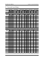
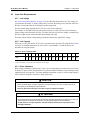
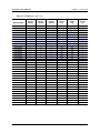
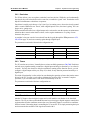
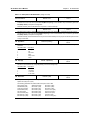
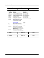
2.2 Power and Current Ratings
115 Vac Ratings
Model
number
Normal Duty Input current (A) Output current (A) Heavy Duty Input current (A) Output current (A)
HP kW -- 115 Vac -- 230 Vac HP kW -- 230 Vac -- 230 Vac
X5C1S010C
1 0.75 -- 15 -- 4.2 0.5 0.37 -- 11 -- 2.2
230 Vac Ratings
Model
number
Normal Duty Input current (A) Output current (A) Heavy Duty Input current (A) Output current (A)
HP kW 200 Vac 230 Vac 200 Vac 230 Vac HP kW 200 Vac 230 Vac 200 Vac 230 Vac
X5C20010C
1 0.75 5.6 4.8 4.8 4.2 0.5 0.37 2.9 2.5 2.5 2.2
X5C20020C
2 1.5 9 7.8 7.8 6.8 1 0.75 5.6 4.8 4.8 4.2
X5C20030C
3 2.2 12.7 11 11 9.6 2 1.5 9 7.8 7.8 6.8
X5C20050C
5 4 20.2 17.5 17.5 15.2 3 2.2 12.7 11 11 9.6
X5C20075C
7.5 5.5 29.2 25.3 25.3 22 5 4 20.2 17.5 17.5 15.2
X5C20100C
10 7.5 37.2 32.2 37.2 28 7.5 5.5 29.2 25.3 25.3 22
X5C20150C
15 11 52.1 46.4 48.3 42 10 7.5 37.2 32.2 37.2 28
X5C20200C
20 15 68.3 57.4 62.1 54 15 11 52.1 46.4 48.3 42
X5C20250C
25 18.5 82.3 73.8 78.2 68 20 15 68.3 57.4 62.1 54
X5C20300C
30 22 96 84 92 80 25 18.5 82.3 73.8 78.2 68
NOTE: All 230 Vac models can be operated at single-phase, with 50% derating
460 Vac Ratings
Model
number
Normal Duty Input current (A) Output current (A) Heavy Duty Input current (A) Output current (A)
HP kW 380 Vac 460 Vac 380 Vac 460 Vac HP kW 380 Vac 460 Vac 380 Vac 460 Vac
X5C40010C
1 0.75 3.0 2.4 2.4 2.1 0.5 0.37 1.6 1.3 1.3 1.1
X5C40020C
2 1.5 5.2 3.9 3.8 3.4 1 0.75 3.0 2.4 2.4 2.1
X5C40030C
3 2.2 7.2 5.6 5.1 4.8 2 1.5 5.2 3.9 3.8 3.4
X5C40050C
5 412 8.88.97.63 2.2 7.2 5.6 5.1 4.8
X5C40075C
7.5 5.5 15 12.8 12 11 5 412 8.8 8.9 7.6
X5C40100C
10 7.5 19.7 16.3 15.6 14 7.5 5.5 15 12.8 12 11
X5C40150C
15 11 30.9 25.8 23 21 10 7.5 19.7 16.3 15.6 14
X5C40200C
20 15 40 33.3 31 27 15 11 30.9 25.8 23 21
X5C40250C
25 18 46.3 40 37 34 20 15 40 33.3 31 27
X5C40300C
30 22 57.5 47.8 43 40 25 18 46.3 40 37 34
X5C40400C
40 30 73.2 62.4 61 52 30 22 57.5 47.8 43 40
X5C40500C
50 37 82 78 71 65 40 30 73.2 62.4 61 52
X5C40600C
60 45 94 80 86 77 50 37 82 78 71 65
X5C40750C
75 55 114 99 105 96 60 45 94 80 86 77
X5C41000C
100 75 149 129 140 124 75 55 114 99 105 96
X5C41250D
125 90 168 156 168 156 100 75 140 124 140 124
X5C41500D
150 110 205 180 205 180 125 90 168 156 168 156
X5C42000D
200 132 240 240 240 240 150 110 205 180 205 180

X5 AC Drive User’s Manual Chapter 2: Technical Characteristics
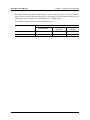
DPD00089A - 17 - © 2009 Vacon Incorporated All Rights Reserved
575 Vac Ratings
Model
number
Normal Duty Input current (A) Output current (A) Heavy Duty Input current (A) Output current (A)
HP kW - 575 Vac - 575 Vac HP kW - 575 Vac - 575 Vac
X5C50010C
1 0.75 - 2.0 - 1.7 0.5 0.37 - 1.2 - 0.9
X5C50020C
2 1.5 - 3.6 - 2.7 1 0.75 - 2.0 - 1.7
X5C50030C
3 2.2 - 5.0 - 3.9 2 1.5 - 3.6 - 2.7
X5C50050C
5 4- 7.6-6.13 2.2 - 5.0 - 3.9
X5C50075C
7.5 5.5 - 10.4 - 9.0 5 4- 7.6 - 6.1
X5C50100C
10 7.5 - 14.1 - 11.0 7.5 5.5 - 10.4 - 9.0
X5C50150C
15 11 - 23 - 17 10 7.5 - 14.1 - 11
X5C50200C
20 15 - 31 - 22 15 11 - 23 - 17
X5C50250C
25 18 - 37 - 27 20 15 - 31 - 22
X5C50300C
30 22 - 39.5 - 32 25 18 - 37 - 27
X5C50400C
40 30 - 49 - 41 30 22 - 39.5 - 32
X5C50500C
50 37 - 58 - 52 40 30 - 49 - 41
X5C50600C
60 45 - 68 - 62 50 37 - 58 - 52
X5C50750C
75 55 - 82 - 77 60 45 - 68 - 62
X5C51000C
100 75 - 107 - 99 75 55 - 82 - 77
X5C51250D
125 90 - 125 - 125 100 75 - 99 - 99
X5C51500D
150 110 - 144 - 144 125 90 - 125 - 125
X5C52000D
200 132 - 192 - 192 150 110 - 144 - 144

X5 AC Drive User’s Manual Chapter 2: Technical Characteristics
DPD00089A - 18 - © 2009 Vacon Incorporated All Rights Reserved
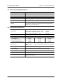
2.3 Environmental Specifications
2.4 Electrical Specifications
Note: Unit Rated kVA = rated Voltage x rated Current x 1.732
Operating temperature -10 °C to +40 °C (14 °F to 104 °F)
Storage temperature –20 °C to +65 °C (-4 °F to 149 °F)
Humidity 0% to 95% non-condensing
Altitude 1000 m (3300 ft) without derating
Maximum vibration per EN50178 (1g @ 57-150 Hz)
Acoustic noise 80 dba sound power at 1 m (3 ft), maximum
Cooling
1-5 HP models: Natural convection
7.5 to 200.0 HP models: Forced air (temperature-controlled external fan)
The 575 Vac, 5 HP model has a fan.
Input voltage
X5C1x models: 115 Vac, 1 phase, +/- 10% 1 HP
X5C2x models: 200-230 Vac, 3 phase, +/- 15% 1-30 HP
X5C4x models: 380-460 Vac, 3 phase, +/- 15% 1-200 HP
X5C5x models: 575Vac, 3 phase, +/-15% 1-200 HP
Line frequency 50 / 60 Hz ±2 Hz
Source kVA (maximum) 10 times the unit rated kVA, 65kA maximum (see note below)
DC bus voltage for:
Overvoltage trip
Dynamic brake activation
Nominal undervoltage (UV) trip
115/230 Vac models
406 Vdc
388 Vdc
199 Vdc
460 Vac models
814 Vdc
776 Vdc
397 Vdc
575 Vac models
1017 Vdc
970 Vdc
497 Vdc
Control system
V/Hz or Sensorless Vector Control (SVC)
Carrier frequency = 1 - 16 kHz, programmable; 8 kHz max. for 125-200 HP
models
Output voltage 3-phase: 0 to 100% of incoming voltage (0-230 Vac for 115 Vac models)
Overload capacity
120% of rated RMS current for 60 seconds (normal duty rating)
150% of rated RMS current for 60 seconds (heavy duty rating)
Frequency range 0.1 to 400 Hz
Frequency stability 0.1 Hz (digital), 0.1% (analog) over 24 hours +/- 10 °C
Frequency setting
By keypad, or by external signal (0 to 5 Vdc; 0 to 10 Vdc; 0/4 to 20 mA) or by
pulse train up to 100kHz

X5 AC Drive User’s Manual Chapter 2: Technical Characteristics
DPD00089A - 19 - © 2009 Vacon Incorporated All Rights Reserved
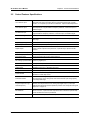
2.5 Control Features Specifications
Vin1 reference input
0-5/10 Vdc, 0/4-20 mAdc (250 Ω load)
6FS pulse train input from another drive, 0-1/10/100 kHz pulse input, inverted
function, 0-5-10 bipolar input, broken wire detection. Span and offset adjustment.
Vin2 reference input
0-5/10 Vdc, 0-5-10 bipolar input, inverted function, broken wire detection, span and
offset adjustment. Programmable for frequency reference, current limit input, or
feedback signal.
Cin reference input
0/4-20 mAdc (50 Ω load), inverted function, span and offset adjustment.
Programmable for frequency reference, current limit input, or feedback signal.
Reference voltage 10 Vdc (10 mAdc maximum)
Digital inputs - 10
Off=0 to 3 Vdc; On=10 to 32 Vdc (pull-up logic), selectable between pull-up and pull-
down logic
Digital supply voltage 24 Vdc (150 mAdc maximum)
Preset frequencies 4 inputs for 15 preset frequencies (selectable)
Digital outputs
2 SPDT relay outputs - 130 Vac, 1 A/250 Vac, 0.5 A
2 open collector outputs 50 mA per device; 2 optional relays; optional encoder
interface
Digital pulse train output Open collector output pulse train proportional to output frequency
Vmet analog output 0 to 10 Vdc (5 mAdc maximum)
Imet analog output 0/4-20 mAdc output into a 500 Ω load (maximum)
DC holding / injection braking
At start, stop, by frequency with adjustable current level and time or continuous DC
injection by digital input.
Current limit Four quadrant adjustable from 5 to 150%
Speed ramps Primary and alternate adjustable from 0.1 to 3200.0 seconds
Voltage boost Adjustable fixed boost or adjustable auto boost
Voltage characteristic V/Hz: Linear, pump, fan, or 2-piece linear. Also sensorless vector (SVC).
Timed overload
Adjustable inverse time trip (shear pin, 30 seconds, 60 seconds, 5 minutes), for
standard or inverter-duty motors
Protective features
Overcurrent, overvoltage fault, ground fault, short circuit, dynamic brake overload,
drive temperature, power wiring fault, drive timed overload, input voltage quality,
overvoltage ridethrough
Program Sequence Logic
Controller (PSLC)
25-step (with ability to branch), PLC-type functionality that can control speed,
direction, and ramps based on time, analog input, digital input, or pulse input.
Addressable outputs and real-time operations possible. See “Using the X5 Program
Sequencer” on page 111.
PID Feedback
Process control available with the use of a customer-supplied transducer, either 0-
10 Vdc, 4-20 mA, or optical encoder input to the drive. Includes an optional sleep
mode, activated when the loop is satisfied.
Serial communications Modbus, DeviceNet option, Ethernet IP option, Modbus TCP/IP option

X5 AC Drive User’s Manual Chapter 2: Technical Characteristics
DPD00089A - 20 - © 2009 Vacon Incorporated All Rights Reserved
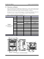
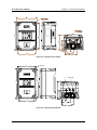
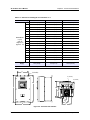
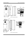
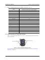
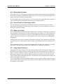
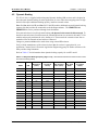
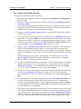
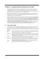
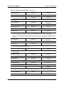
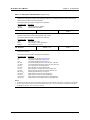
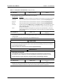
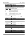
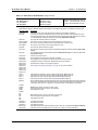
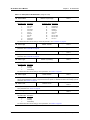
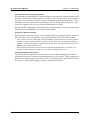
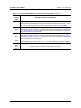
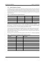
2.6 Dimensions and Weights
Table 2-2 lists dimensions and weights for the X5 frame size 0, 1, 2, and 3 models. Dimensions and
weights for the X5 frame size 4 and 5 models are shown in Table 2-3 on page 22. You may wish to
refer to the cross-reference table on page 15 for X5 model numbers / frame sizes.
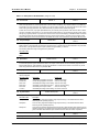
See Figures 2-2, 2-2, 2-3, 2-4, 2-5, and 2-6 on pages 21 - 23 for locations of dimensions. Dimensions
A onward are in inches / millimeters (in/mm). Weight is in pounds / kilograms (lb/kg).
Figure 2-1: X5 Frame Size 0 Models
Table 2-2: Dimensions and Weights for Frame Sizes 0 - 2
Frame 0 1 / 1A 2 / 2A
Dimensions
in (mm)
(See X5 diagrams on pages
21 through 23)
A 9.47 (241) 12.01 (305) 17.38 (441)
B 6.50 (165) 8.72 (221) 10.75 (273)
C 6.08 (155) 8.49 (216) / 6.51 (166) 9.89 (251) / 7.91 (201)
D 8.45 (215) 11.03 (280) 16.50 (419)
E 5.69 (145) 7.88 (200) 9.76 (248)
F 0.28 (7.11) 0.28 (7) 0.41 (10)
G 3.84 (98) 4.05 (103) 4.72 (120)
H 2.77 (70) N/A N/A
J 1.93 (49) 2.31 (59) 2.88 (73)
K 2.85 (72) 3.94 (100) 4.84 (123)
L 3.75 (95) 5.56 (1.41) 6.88 (175)
M 0.88 (22) 0.88 (22) 1.38 (35)
N N/A N/A 1.13 (29)
P N/A N/A N/A
Q N/A N/A N/A
Weight lb (kg) 8.5 (3.85) 14.0 (6.35) 29.5 (13.38)
E
A
B
D
F
M
C
G
H
L
K
J
Page is loading ...
Page is loading ...
Page is loading ...
Page is loading ...
Page is loading ...
Page is loading ...
Page is loading ...
Page is loading ...
Page is loading ...
Page is loading ...
Page is loading ...
Page is loading ...
Page is loading ...
Page is loading ...
Page is loading ...
Page is loading ...
Page is loading ...
Page is loading ...
Page is loading ...
Page is loading ...
Page is loading ...
Page is loading ...
Page is loading ...
Page is loading ...
Page is loading ...
Page is loading ...
Page is loading ...
Page is loading ...
Page is loading ...
Page is loading ...
Page is loading ...
Page is loading ...
Page is loading ...
Page is loading ...
Page is loading ...
Page is loading ...
Page is loading ...
Page is loading ...
Page is loading ...
Page is loading ...
Page is loading ...
Page is loading ...
Page is loading ...
Page is loading ...
Page is loading ...
Page is loading ...
Page is loading ...
Page is loading ...
Page is loading ...
Page is loading ...
Page is loading ...
Page is loading ...
Page is loading ...
Page is loading ...
Page is loading ...
Page is loading ...
Page is loading ...
Page is loading ...
Page is loading ...
Page is loading ...
Page is loading ...
Page is loading ...
Page is loading ...
Page is loading ...
Page is loading ...
Page is loading ...
Page is loading ...
Page is loading ...
Page is loading ...
Page is loading ...
Page is loading ...
Page is loading ...
Page is loading ...
Page is loading ...
Page is loading ...
Page is loading ...
Page is loading ...
Page is loading ...
Page is loading ...
Page is loading ...
Page is loading ...
Page is loading ...
Page is loading ...
Page is loading ...
Page is loading ...
Page is loading ...
Page is loading ...
Page is loading ...
Page is loading ...
Page is loading ...
Page is loading ...
Page is loading ...
Page is loading ...
Page is loading ...
Page is loading ...
Page is loading ...
Page is loading ...
Page is loading ...
Page is loading ...
Page is loading ...
Page is loading ...
Page is loading ...
Page is loading ...
Page is loading ...
Page is loading ...
Page is loading ...
Page is loading ...
Page is loading ...
Page is loading ...
Page is loading ...
Page is loading ...
Page is loading ...
Page is loading ...
Page is loading ...
Page is loading ...
Page is loading ...
Page is loading ...
Page is loading ...
-
 1
1
-
 2
2
-
 3
3
-
 4
4
-
 5
5
-
 6
6
-
 7
7
-
 8
8
-
 9
9
-
 10
10
-
 11
11
-
 12
12
-
 13
13
-
 14
14
-
 15
15
-
 16
16
-
 17
17
-
 18
18
-
 19
19
-
 20
20
-
 21
21
-
 22
22
-
 23
23
-
 24
24
-
 25
25
-
 26
26
-
 27
27
-
 28
28
-
 29
29
-
 30
30
-
 31
31
-
 32
32
-
 33
33
-
 34
34
-
 35
35
-
 36
36
-
 37
37
-
 38
38
-
 39
39
-
 40
40
-
 41
41
-
 42
42
-
 43
43
-
 44
44
-
 45
45
-
 46
46
-
 47
47
-
 48
48
-
 49
49
-
 50
50
-
 51
51
-
 52
52
-
 53
53
-
 54
54
-
 55
55
-
 56
56
-
 57
57
-
 58
58
-
 59
59
-
 60
60
-
 61
61
-
 62
62
-
 63
63
-
 64
64
-
 65
65
-
 66
66
-
 67
67
-
 68
68
-
 69
69
-
 70
70
-
 71
71
-
 72
72
-
 73
73
-
 74
74
-
 75
75
-
 76
76
-
 77
77
-
 78
78
-
 79
79
-
 80
80
-
 81
81
-
 82
82
-
 83
83
-
 84
84
-
 85
85
-
 86
86
-
 87
87
-
 88
88
-
 89
89
-
 90
90
-
 91
91
-
 92
92
-
 93
93
-
 94
94
-
 95
95
-
 96
96
-
 97
97
-
 98
98
-
 99
99
-
 100
100
-
 101
101
-
 102
102
-
 103
103
-
 104
104
-
 105
105
-
 106
106
-
 107
107
-
 108
108
-
 109
109
-
 110
110
-
 111
111
-
 112
112
-
 113
113
-
 114
114
-
 115
115
-
 116
116
-
 117
117
-
 118
118
-
 119
119
-
 120
120
-
 121
121
-
 122
122
-
 123
123
-
 124
124
-
 125
125
-
 126
126
-
 127
127
-
 128
128
-
 129
129
-
 130
130
-
 131
131
-
 132
132
-
 133
133
-
 134
134
-
 135
135
-
 136
136
-
 137
137
-
 138
138


Danfoss VACON X Series User manual
- Type
- User manual
Ask a question and I''ll find the answer in the document
Finding information in a document is now easier with AI
Related papers
-
Vacon VACON X Series User manual
-
Vacon 50X User manual
-
-
Vacon VACONOptionBoards Installation guide
-
-
-
-
Vacon 20 User guide
-
-
Other documents
-
Vacon X5 User manual
-
Big Ass Fans Basic 6 Operating instructions
-
-
 Consew CSM1000 User manual
-
ABB B Series Programming Manual
-
 TB Wood's x4 User manual
-
GE AF-300 User manual
-
-
 Magnetek HPV® 900 Series 2 - AC Elevator Drive Owner's manual
-
 Magnetek HPV 900 Series 2 Technical Manual


